
Section
4 Shell envelope framing
4.1 General
4.1.2 The requirements
in this Section apply to longitudinally and transversely framed shell
envelopes.
4.2 Bottom outboard longitudinal stiffeners
4.2.1 Bottom
outboard longitudinal stiffeners are to be supported by transverse
web frames, floors, bulkheads, or other primary structure, generally
spaced not more than 2 m apart.
4.2.2 Bottom
outboard longitudinals are to be continuous through the supporting
structures.
4.2.3 Where it
is impracticable to comply with the requirements of Pt 6, Ch 4, 4.2 Bottom outboard longitudinal stiffeners 4.2.2, or where it is proposed to terminate
the bottom outboard longitudinals in way of the transom, bulkheads
or integral tank boundaries, all longitudinals are to be bracketed
in way of their end connections to maintain the continuity of structural
strength. Particular attention is to be taken to ensure accurate alignment
of the brackets.
4.2.4 The requirements
for section modulus, inertia and web area are to be determined from
the general equations given in Pt 6, Ch 3, 1.17 Stiffening general,
using the design pressures from Pt 5, Ch 3, 3.1 Hull structures or Pt 5, Ch 4, 3.1 Hull structures for
non-displacement or displacement craft as appropriate, and the coefficients ΦZ, ΦI, and ΦA as detailed in Table 3.1.1 Section modulus, inertia and web
area coefficients in Chapter 3 for the load
model (b).
4.3 Bottom outboard longitudinal primary stiffeners
4.3.1 Bottom
outboard longitudinal primary stiffeners are to be supported by deep
transverse web frames, floors, bulkheads, or other primary structures,
generally spaced not more than 4 m apart.
4.3.2 Bottom
outboard longitudinal primary stiffeners are to be continuous through
transverse bulkheads and supporting structures.
4.3.3 Where it
is impracticable to comply with the requirements of Pt 6, Ch 4, 4.3 Bottom outboard longitudinal primary stiffeners 4.3.2, or where it is proposed to terminate
the stiffeners in way of the transom, bulkheads or integral tank boundaries,
they are to be bracketed in way of their end connections to maintain
the continuity of structural strength. Particular care is to be taken
to ensure accurate alignment of the brackets. All brackets are to
be `soft toed' and are to terminate on suitable supporting structure
capable of carrying the transmitted bending moment.
4.3.4 The requirements
for section modulus, inertia and web area are to be determined from
the general equations given in Pt 6, Ch 3, 1.17 Stiffening general,
using the design pressures from Pt 5, Ch 3, 3.1 Hull structures or Pt 5, Ch 4, 3.1 Hull structures for
non-displacement or displacement craft as appropriate, and the coefficients ΦZ, ΦI, and ΦA as detailed in Table 3.1.1 Section modulus, inertia and web
area coefficients in Chapter 3 for the load
model (a).
4.4 Bottom outboard transverse stiffeners
4.4.1 Bottom
outboard transverse stiffeners are defined as local stiffening members
which support the bottom shell and which may be continuous or intercostal.
4.4.2 The requirements
for section modulus, inertia and web area are to be determined from
the general equations given in Pt 6, Ch 3, 1.17 Stiffening general,
using the design pressures from Pt 5, Ch 3, 3.1 Hull structures or Pt 5, Ch 4, 3.1 Hull structures for
non-displacement or displacement craft as appropriate, and the coefficients ΦZ, ΦI, and ΦA as detailed in Table 3.1.1 Section modulus, inertia and web
area coefficients in Chapter 3 for the load
model (b).
4.5 Bottom outboard transverse frames
4.5.1 Bottom
outboard transverse frames are defined as stiffening members which
support the bottom shell. They are to be effectively continuous and
bracketed at their end connections to side frames and bottom floors
as appropriate.
4.5.2 The requirements
for section modulus, inertia and web area are to be determined from
the general equations given in Pt 6, Ch 3, 1.17 Stiffening general,
using the design pressures from Pt 5, Ch 3, 3.1 Hull structures or Pt 5, Ch 4, 3.1 Hull structures for
non-displacement or displacement craft as appropriate, and the coefficients ΦZ, ΦI, and ΦA as detailed in Table 3.1.1 Section modulus, inertia and web
area coefficients in Chapter 3 for the load
model (a).
4.6 Bottom outboard transverse web frames
4.6.1 Bottom
outboard transverse web frames are defined as primary stiffening members
which support bottom shell longitudinals. They are to be continuous
and substantially bracketed at their end connections to side web frames
and bottom floors.
4.6.2 Where it
is impracticable to comply with the requirements of Pt 6, Ch 4, 4.6 Bottom outboard transverse web frames 4.6.1, or where it is proposed to terminate
the web frames in way of bulkheads or integral tank boundaries, they
are to be bracketed in way of their end connections to maintain the
continuity of structural strength. Particular attention is to be taken
to ensure accurate alignment of the brackets. All brackets are to
be `soft toed' and are to terminate on suitable supporting structure
capable of carrying the transmitted bending moment.
4.6.3 The requirements
for section modulus, inertia and web area are to be determined from
the general equations given in Pt 6, Ch 3, 1.17 Stiffening general,
using the design pressures from Pt 5, Ch 3, 3.1 Hull structures or Pt 5, Ch 4, 3.1 Hull structures for
non-displacement or displacement craft as appropriate, and the coefficients ΦZ, ΦI, and ΦA as detailed in Table 3.1.1 Section modulus, inertia and web
area coefficients in Chapter 3 for the load
model (a).
4.7 Bottom inboard longitudinal stiffeners
4.8 Bottom inboard longitudinal primary stiffeners
4.9 Bottom inboard transverse stiffeners
4.10 Bottom inboard transverse frames
4.11 Bottom inboard transverse web frames
4.12 Side outboard longitudinal stiffeners
4.12.1 The side
outboard longitudinal stiffeners are to be supported by transverse
web frames, bulkheads, or other primary structure, generally spaced
not more than 2 m apart.
4.12.2 Side
outboard longitudinals are to be continuous through the supporting
structures.
4.12.3 Where
it is impracticable to comply with the requirements of Pt 6, Ch 4, 4.12 Side outboard longitudinal stiffeners 4.12.2, or where it is proposed to
terminate the side outboard longitudinals in way of the transom, bulkheads
or integral tank boundaries, they are to be bracketed in way of their
end connections to maintain the continuity of structural strength.
Particular attention is to be taken to ensure accurate alignment of
the brackets.
4.12.4 The requirements
for section modulus, inertia and web area are to be determined from
the general equations given in Pt 6, Ch 3, 1.17 Stiffening general,
using the design pressures from Pt 5, Ch 3, 3.1 Hull structures or Pt 5, Ch 4, 3.1 Hull structures for
non-displacement or displacement craft as appropriate, and the coefficients ΦZ, ΦI, and ΦA as detailed in Table 3.1.1 Section modulus, inertia and web
area coefficientsin Chapter 3 for the load
model (b).
4.13 Side outboard longitudinal primary stiffeners
4.13.1 Side
outboard longitudinal primary stiffeners are to be supported by side
transverse web frames, bulkheads, or other primary structure, generally
spaced not more than 4 m apart.
4.13.2 Side
outboard longitudinal primary stiffeners are to be continuous through
transverse bulkheads and supporting structures.
4.13.3 Where
it is impracticable to comply with the requirements of Pt 6, Ch 4, 4.13 Side outboard longitudinal primary stiffeners 4.13.2, or where it is proposed to
terminate the side outboard longitudinals in way of the transom, bulkheads
or integral tank boundaries, they are to be bracketed in way of their
end connections to maintain the continuity of structural strength.
Particular care is to be taken to ensure accurate alignment of the
brackets. All brackets are to be `soft toed' and are to terminate
on suitable supporting structure capable of carrying the transmitted
bending moment.
4.13.4 The requirements
for section modulus, inertia and web area are to be determined from
the general equations given in Pt 6, Ch 3, 1.17 Stiffening general,
using the design pressures from Pt 5, Ch 3, 3.1 Hull structures or Pt 5, Ch 4, 3.1 Hull structures for
non-displacement or displacement craft as appropriate, and the coefficients ΦZ, ΦI, and ΦA as detailed in Table 3.1.1 Section modulus, inertia and web
area coefficientsin Chapter 3 for the load
model (a).
4.14 Side outboard transverse stiffeners
4.14.1 Side
outboard transverse stiffeners are defined as local stiffening members
supporting the side shell and may be continuous or intercostal.
4.14.2 The requirements
for section modulus, inertia and web area are to be determined from
the general equations given in Pt 6, Ch 3, 1.17 Stiffening general,
using the design pressures from Pt 5, Ch 3, 3.1 Hull structures or Pt 5, Ch 4, 3.1 Hull structures for
non-displacement or displacement craft as appropriate, and the coefficients ΦZ, ΦI, and ΦA as detailed in Table 3.1.1 Section modulus, inertia and web
area coefficients in Chapter 3 for the load
model (b).
4.15 Side outboard transverse frames
4.15.1 Side
outboard transverse frames are defined as stiffening members supporting
the side shell and spanning continuously between bottom floors/frames
and decks. They are to be effectively constrained against rotation
at their end connections.
4.15.2 The requirements
for section modulus, inertia and web area are to be determined from
the general equations given in Pt 6, Ch 3, 1.17 Stiffening general,
using the design pressures from Pt 5, Ch 3, 3.1 Hull structures or Pt 5, Ch 4, 3.1 Hull structures for
non-displacement or displacement craft as appropriate, and the coefficients ΦZ, ΦI, and ΦA as detailed in Table 3.1.1 Section modulus, inertia and web
area coefficients in Chapter 3 for the load
model (a).
4.16 Side outboard transverse web frames
4.16.1 Side
outboard transverse web frames are defined as primary stiffening members
which support side shell longitudinals. They are to be continuous
and substantially bracketed at their head and heel connections to
deck beams and bottom web frames respectively.
4.16.2 Where
it is impracticable to comply with the requirements of Pt 6, Ch 4, 4.16 Side outboard transverse web frames 4.16.1, or where it is proposed to
terminate the side outboard longitudinals in way of bulkheads or integral
tank boundaries, they are to be bracketed in way of their end connections
to maintain the continuity of structural strength. Particular care
is to be taken to ensure accurate alignment of the brackets. All brackets
are to be `soft toed' and are to terminate on suitable supporting
structure capable of carrying the transmitted bending moment.
4.16.3 The requirements
for section modulus, inertia and web area are to be determined from
the general equations given in Pt 6, Ch 3, 1.17 Stiffening general,
using the design pressures from Pt 5, Ch 3, 3.1 Hull structures or Pt 5, Ch 4, 3.1 Hull structures for
non-displacement or displacement craft as appropriate, and the coefficients ΦZ, ΦI, and ΦA as detailed in Table 3.1.1 Section modulus, inertia and web
area coefficients in Chapter 3 for the load
model (a).
4.17 Side inboard longitudinal stiffeners
4.18 Side inboard longitudinal primary stiffeners
4.19 Side inboard transverse stiffeners
4.20 Side inboard transverse frames
4.21 Side inboard transverse web frames
4.22 Wet-deck longitudinal stiffeners
4.22.1 The wet-deck
longitudinal stiffeners are to be supported by transverse web frames,
bulkheads, or other primary structure, generally spaced not more than
2 m apart.
4.22.2 Wet-deck
longitudinals are to be continuous through the supporting structures.
4.22.3 Where
it is impracticable to comply with the requirements of Pt 6, Ch 4, 4.22 Wet-deck longitudinal stiffeners 4.22.2, or where it is proposed to
terminate the wet-deck longitudinals in way of the transom, bulkheads
or integral tank boundaries, they are to be bracketed in way of their
end connections to maintain the continuity of structural strength.
Particular care is to be taken to ensure accurate alignment of the
brackets.
4.22.4 The requirements
for section modulus, inertia and web area are to be determined from
the general equations given in Pt 6, Ch 3, 1.17 Stiffening general,
using the design pressures from Pt 5, Ch 3, 3.1 Hull structures or Pt 5, Ch 4, 3.1 Hull structures for
non-displacement or displacement craft as appropriate, and the coefficients ΦZ, ΦI, and ΦA as detailed in Table 3.1.1 Section modulus, inertia and web
area coefficients in Chapter 3 for the load
model (b).
4.23 Wet-deck longitudinal primary stiffeners
4.23.1 Wet-deck
longitudinal primary stiffeners are to be supported by transverse
web frames, bulkheads, or other primary structure, generally spaced
not more than 4 m apart.
4.23.2 Wet-deck
longitudinal primary stiffeners are to be continuous through transverse
bulkheads and supporting structures.
4.23.3 Where
it is impracticable to comply with the requirements of Pt 6, Ch 4, 4.23 Wet-deck longitudinal primary stiffeners 4.23.2, or where it is proposed to
terminate the wet-deck longitudinals in way of the transom, bulkheads
or integral tank boundaries, they are to be bracketed in way of their
end connections to maintain the continuity of structural strength.
Particular care is to be taken to ensure accurate alignment of the
brackets. All brackets are to be `soft toed' and are to terminate
on suitable supporting structure capable of carrying the transmitted
bending moment.
4.23.4 The requirements
for section modulus, inertia and web area are to be determined from
the general equations given in Pt 6, Ch 3, 1.17 Stiffening general,
using the design pressures from Pt 5, Ch 3, 3.1 Hull structures or Pt 5, Ch 4, 3.1 Hull structures for
non-displacement or displacement craft as appropriate, and the coefficients ΦZ, ΦI, and ΦA as detailed in Table 3.1.1 Section modulus, inertia and web
area coefficients in Chapter 3 for the load
model (a).
4.24 Wet-deck transverse stiffeners
4.24.1 Wet-deck
transverse stiffeners are defined as local stiffening members supporting
the wet-deck and may be continuous or intercostal.
4.24.2 The requirements
for section modulus, inertia and web area are to be determined from
the general equations given in Pt 6, Ch 3, 1.17 Stiffening general,
using the design pressures from Pt 5, Ch 3, 3.1 Hull structures or Pt 5, Ch 4, 3.1 Hull structures for
non-displacement or displacement craft as appropriate, and the coefficients ΦZ, ΦI, and ΦA as detailed in Table 3.1.1 Section modulus, inertia and web
area coefficients in Chapter 3 for the load
model (b).
4.25 Wet-deck transverse frames
4.25.1 Wet-deck
transverse frames are defined as stiffening members which support
the wet-deck. They are to be effectively continuous and bracketed
at their end connections to side frames.
4.25.2 The requirements
for section modulus, inertia and web area are to be determined from
the general equations given in Pt 6, Ch 3, 1.17 Stiffening general,
using the design pressures from Pt 5, Ch 3, 3.1 Hull structures or Pt 5, Ch 4, 3.1 Hull structures for
non-displacement or displacement craft as appropriate, and the coefficients ΦZ, ΦI, and ΦA as detailed in Table 3.1.1 Section modulus, inertia and web
area coefficients in Chapter 3 for the load
model (a).
4.26 Wet-deck transverse web frames
4.26.1 Wet-deck
transverse web frames are defined as primary stiffening members which
support wet-deck longitudinals. They are to be continuous and substantially
bracketed at their end connections to side transverse web frames.
4.26.2 Where
it is impracticable to comply with the requirements of Pt 6, Ch 4, 4.26 Wet-deck transverse web frames 4.26.1, or where it is proposed to
terminate the wet-deck longitudinals in way of the bulkheads or integral
tank boundaries, they are to be bracketed in way of their end connections
to maintain the continuity of structural strength. Particular care
is to be taken to ensure accurate alignment of the brackets. All brackets
are to be `soft toed' and are to terminate on suitable supporting
structure capable of carrying the transmitted bending moment.
4.26.3 The requirements
for section modulus, inertia and web area are to be determined from
the general equations given in Pt 6, Ch 3, 1.17 Stiffening general,
using the design pressures from Pt 5, Ch 3, 3.1 Hull structures or Pt 5, Ch 4, 3.1 Hull structures for
non-displacement or displacement craft as appropriate, and the coefficients ΦZ, ΦI, and ΦA as detailed in Table 3.1.1 Section modulus, inertia and web
area coefficients in Chapter 3 for the load
model (a).
4.26.5 Primary
transverse web frames that link the strength deck to the wet-deck
structure and which carry the transverse global loading are additionally
to comply with Pt 6, Ch 6, 3.4 Torsional strength.
4.26.6 Particular
attention is to be taken to ensure that the continuity of transverse
structural strength is maintained. All primary transverse members
are to be continuous through the inboard side structure and integrated
into transverse bulkheads or other primary structure within each hull
(see
Figure 4.4.1 End connection details, wet-deck structure).
In the case of trimaran type craft the primary transverse members
are to be continuous through the centre hull. Additionally the side
inboard shell plating in way of the intersection is to be increased
locally by not less than 50 per cent.
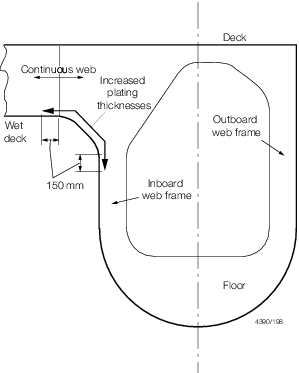
Figure 4.4.1 End connection details, wet-deck structure
4.27 Lower hull (SWATH)
4.27.1 Where
the lower hull structure incorporates ring frames and attached shell
plating fitted between bulkheads or diaphragms, the scantlings of
the lower hull shell stiffening may be derived from an established
method for stiffening analysis or Recognised Standard for pressure
vessels using the design loading from Pt 5, Ch 4, 3.1 Hull structures Modes of failure to be considered are buckling,
frame collapse, inter frame shell collapse and overall frame shell
collapse between bulkheads. A copy of the direct calculations is to
be submitted for consideration.
4.28 Scantlings of end brackets
4.28.1 The scantlings
of end brackets in way of transverse web frames/crossdeck primary
structure which carry transverse global loading, are to be as large
as practicable and be additionally reinforced as necessary. The webs
of deep brackets are to be stiffened as necessary to resist buckling, see also
Pt 6, Ch 6, 3.5 Strength of cross-deck structures.
|