
Section
2 Structural design
2.1 General
2.1.2 For
derivation of scantlings of stiffeners, beams, girders, etc. the formulae
in the Rules are normally based on elastic or plastic theory using
simple beam models supported at one or more points and with varying
degrees of fixity at the ends, associated with an appropriate concentrated
distributed load.
2.1.3 The
stiffener, beam or girder strength is defined by a section modulus
and moments of inertia requirements. In addition there are local requirements
for web thickness and flange thickness.
2.2 Effective width of attached plating
2.2.1 For
stiffening members, the geometric properties of rolled or built sections
are to be calculated in association with an effective area of attached
load bearing plating of thickness, t
p, in
mm and an effective breadth, t
p in mm.
2.2.2 The
effective breadth of attached plating to secondary stiffener members b
e, in mm, is to be taken as the lesser of:
-
The actual spacing
of the stiffeners, b, and
-
The greater of
40t
p and 600 mm
-
The effective
breadth of attached plating to primary support members (girders, transverses,
webs, etc.) is to be taken as follows:
but is not to exceed S
S and l are defined in Vol 1, Pt 6, Ch 1, 1.3 Symbols and definitions.
2.3 Section properties
2.3.1 The
effective geometric properties of rolled or built sections are to
be calculated directly from the dimensions of the section and associated
effective area of attached plating. Where the web of the section is
not normal to the actual plating, and the angle exceeds 20°, the
properties of the section are to be determined about an axis parallel
to the attached plating.
2.3.2 If applicable,
idealised section properties may be calculated as described in the
Complementary Rules.
2.4 Convex curvature correction
2.4.1 The
thickness of plating as determined by the Rules may be reduced where
significant curvature exists between the supporting members. In such
cases a plate curvature correction factor may be applied:
see
Figure 2.2.1 Convex curvature
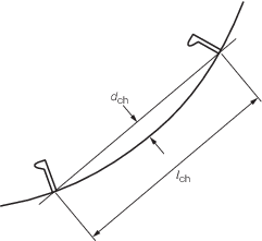
Figure 2.2.1 Convex curvature
2.4.2 The
required section modulus of transverse main and ‘tween deck
frames, which have reasonably constant convex curvature over their
entire length, may be corrected for curvature as follows:
2.5 Aspect ratio correction
2.5.1 The
thickness of plating as determined by the Rules may be reduced when
the panel aspect ratio is taken into consideration. In such cases
a panel aspect ratio correction factor may be applied:
2.6 Determination of span length
2.6.1 The
effective length, l
e, of a stiffening member
is generally less than the overall length, l, by an amount
which depends on the design of the end connections. The span points,
between which the value of l
e is measured
are to be determined as follows:
-
For rolled
or built secondary stiffening members: The span point is to
be taken at the point where the depth of the end bracket, measured
from the face of the member, is equal to the depth of the member.
Where there is no end bracket, the span point is to be measured between
primary member webs. For double bottom construction the span may be
reduced by the depth of primary member web stiffener, see
Figure 2.2.2 Definition of span points.
-
For primary
support members: The span point is to be taken at a point distant
from the end of the member,
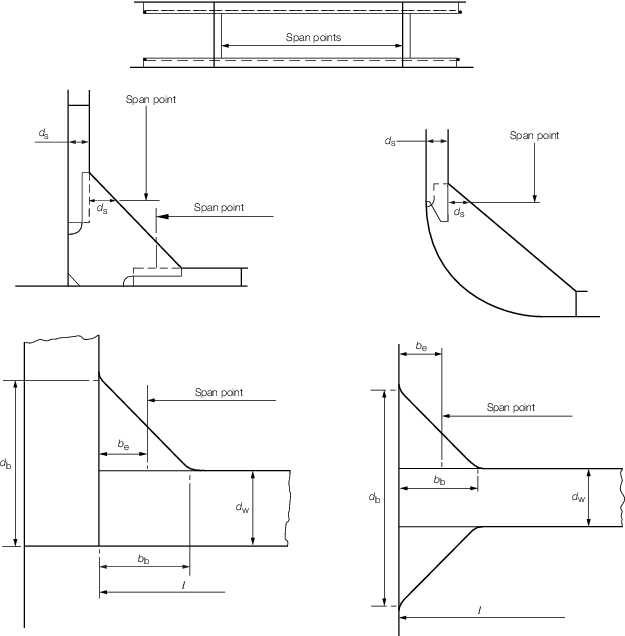
Figure 2.2.2 Definition of span points
2.7 Proportions of stiffener sections
2.8 Grillage structures
2.8.1 For
complex girder systems, a complete structural analysis using numerical
methods may have to be performed to demonstrate that the stress levels
are acceptable when subjected to the most severe and realistic combination
of loading conditions intended.
2.8.2 General
or special purpose computer programs or other analytical techniques
may be used provided that the effects of bending, shear, axial load
and torsion are properly accounted for and the theory and idealisation
used can be justified.
2.8.3 In general,
grillages consisting of slender girders may be idealised as frames
based on beam theory provided proper account of the variations of
geometric properties is taken. For cases where such an assumption
in not applicable, finite element analysis or equivalent methods may
have to be used.
2.9 Detail design
2.9.1 Items
such as details of end connections and scantlings of end brackets
are to be in compliance with the Complementary Rules.
|
| Copyright 2022 Clasifications Register Group Limited, International Maritime Organization, International Labour Organization or Maritime
and Coastguard Agency. All rights reserved. Clasifications Register Group Limited, its affiliates and subsidiaries and their respective
officers, employees or agents are, individually and collectively, referred to in this clause as 'Clasifications Register'. Clasifications
Register assumes no responsibility and shall not be liable to any person for any loss, damage or expense caused by reliance
on the information or advice in this document or howsoever provided, unless that person has signed a contract with the relevant
Clasifications Register entity for the provision of this information or advice and in that case any responsibility or liability is
exclusively on the terms and conditions set out in that contract.
|
 |
|