
Section
3 Model experiments
3.1 General
3.1.1 Model
experiments should generally follow the procedures recommended by
the ITTC (International Towing Tank Conference) for conduct of sea
keeping tests to accurately predict the motions, accelerations and
structural loads on the vessel.
3.2 Model and data collection requirement
3.2.1 Model
scale should be at least 1:50 and its size such that it avoids test
tank wall interference. Weight distribution along both the longitudinal
and transverse directions of the model must be reproduced as correctly
as possible to measure the global loads like vertical and transverse
bending moments, torsion loads and shear forces with reasonable accuracy.
Model construction should consider scaling of bending stiffness as
and where applicable to enable accurate measurement of hydro-elasticity
dependent loads or suitable corrections may be incorporated in the
analysis of measurements.
3.2.2 The
measured data during model tests in waves should be obtained for sufficiently
large number of wave encounters, especially in the case of irregular
seas to enable reasonably reliable and accurate results.
3.2.3 The
data sampling frequency should be sufficiently high, especially for
the measurement of loads induced by impact or structural vibration,
to enable the dynamic property of the loads be recorded reasonably
accurately.
3.3 Loading conditions
3.4 Model test conditions
3.4.1 The
sea area considered to produce the worst operating environment for
a vessel in unrestricted service is the North Atlantic. The most onerous
wave conditions in the North Atlantic with a return period of 20 years
are generally to be used. The wave data and spectrum are as specified
by IACS Recommendation 34. The most onerous wave conditions, which
are often presented as wave contour, are shown in Figure 3.3.1 North Atlantic Wave Contours in 20 years return period.
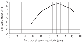
Figure 3.3.1 North Atlantic Wave Contours in 20 years return period
3.4.2 For
a vessel in restricted service, the testing wave conditions are to
be determined from the wave data of the specified service area. A
prior approval of the wave data by LR is required.
3.4.3 The
minimum model test matrix which is required to be carried out is given
in Table 3.3.1 Minimum model test matrix to consist
of the following.
Table 3.3.1 Minimum model test matrix
| Item
|
Test matrix
|
| Speed
|
Three speeds: Including a manoeuvring
speed of 5 knots, 75% and 100% of full service speed
|
| Heading
|
Five headings: Including head, bow
quartering, beam, stern quartering and stern seas
|
| Sea State
|
Sufficient number of sea states in
terms of H
s and T
z combination, in order to catch the maximum motion and loading
components as specified in Vol 4, Pt 1, Ch 3, 3.5 Parameters to be measured 3.5.2
|
3.4.4 Selection
of the speed should consider operation limitation of the vessel in
the selected testing sea state with agreement of LR. In beam, stern
quartering and stern seas, the testing sea states can be reduced to
the most onerous wave conditions with return period of 1 year in the
North Atlantic, or in the specified service area if the vessel is
in restricted service.
3.4.5 The
theoretical analysis can be used to select critical conditions to
reduce the scope of model tests.
3.5 Parameters to be measured
3.5.1 The
basis on which the parameters are chosen for investigation is to be
submitted for approval at the earliest opportunity.
3.5.2 In addition
to those quantities which are normally measured in a model experiment,
the following data are to be obtained where practicable:
-
Motions;
-
Accelerations
at:
Bow – 10 per cent of LPP aft of FP
CG – (depends on the condition tested)
Stern – 10 per cent of LPP forward of AP;
-
Global loads:
as given in Vol 4, Pt 1, Ch 3, 2.3 Load and motion parameters 2.3.1 to
(g);
-
Local loads at
bow and wet deck.
3.5.3 Measurement
of hull motions should preferably be non-intrusive to avoid the effect
of instrumentation on the body motions. Measurement of the encountered
waves are more desirable than that of the stationary waves, and non-intrusive
method of measurement should be preferred to avoid water run-up on
the forward side and ventilation of the back side of the wave probes.
3.5.4 Range,
natural frequency, frequency response and linearity of the accelerometers
are to be included when reporting acceleration data apart from their
sampling rate.
3.5.5 Segmented
models are to be used to measure the global loads like, bending and
torsion moments, shear forces in hull and cross deck structure or
hydro elastic effects like springing and whipping.
-
Segmented model
is to be built in a number of stiff segments connected with force
transducers. The side-hulls and the connection between the side-hulls
(bridging structure) should also be segmented and joined with force
transducers, in the same manner as for the main hull girder. Stiffness
in connections must be enough either (i) to ensure no effect of flexibility
or (ii) to give correct eigenfrequencies depending on whether a stiff
or hydroelastic model will be applied.
-
A model purely
for motion response measurement requires only global mass property
to be represented, including mass, centre of gravity and radii of
inertia.
-
A model for load
measurement is constructed by modelling both the global mass property
and mass distribution as accurately as practicable. Location and number
of cuts in the model are to be determined such that they are able
to measure the most critical load components and the loads at the
critical structural locations.
-
A hydroelastic
model requires modelling the structural properties of the full scale
vessel (bending stiffness, eigenfrequencies and eigenmodes) also.
3.5.6 Measurement
of local loads should preferably be based on both the point pressures
and also forces on a sensibly chosen area on the vessel. Measurements
on panels with scaled ‘dimensions and flexural properties’
or with suitable corrections are recommended compared to the point
pressure measurements:
-
For measurement
of local loads on bow and wet deck, hydroelasticity of the local plating
is to be correctly modelled or suitable corrections to be incorpo
-
Location of transducers,
diameter of the sensor face, the range, frequency response and linearity
of the transducer are to be reported.
-
Measurements should
indicate sampling rates, rise time for the experiment data collection
system. Generally sampling rates in the order of ‘kHz’
would be required.
-
Motions and velocities
at bow and under wet deck relative to incoming wave crest are to be
measured also. They can then be used as basis to analyse or verify
the impact pressures based on either dropping test results or theoretical
analysis approved by LR.
3.5.7 Test
duration for each irregular sea state should be not less than 3 hours
in full scale time to determine the critical motions, accelerations
and global loads, and six hours for the critical local loads. It is
recommended to repeat the most critical test cases for each response
to improve reliability of the measured data.
3.6 Data processing and statistical analysis
3.6.1 Appropriate
steps are to be taken to ensure the unwanted noises due to instruments
or model vibrations be removed from the measured raw data, and the
high frequency components, that do not induce local or global structural
responses, due to wave impacts be filtered out.
3.6.2 The
processed data are to be analysed by appropriate statistic model as
agreed by LR, to establish the best statistic fits to the measured
responses in critical sea states versus the probability of occurrence.
3.7 Details to be submitted
3.7.1 The
following details are to be submitted:
-
A summary of the
model details including its size, weight distribution and construction.
-
A summary of the
testing arrangements and procedures.
-
A summary of the
tank facilities and test equipment.
-
Details of the
different instrumentation used during testing and their calibration
including calibration procedures.
-
Details of the
wave/sea state generation, measurements of waves, responses and loads,
definitions and notations.
-
Details of data
acquisition, reduction and analysis procedures.
-
Tabulated and
plotted output.
|
| Copyright 2022 Clasifications Register Group Limited, International Maritime Organization, International Labour Organization or Maritime
and Coastguard Agency. All rights reserved. Clasifications Register Group Limited, its affiliates and subsidiaries and their respective
officers, employees or agents are, individually and collectively, referred to in this clause as 'Clasifications Register'. Clasifications
Register assumes no responsibility and shall not be liable to any person for any loss, damage or expense caused by reliance
on the information or advice in this document or howsoever provided, unless that person has signed a contract with the relevant
Clasifications Register entity for the provision of this information or advice and in that case any responsibility or liability is
exclusively on the terms and conditions set out in that contract.
|
 |
|