
Section
16 Longitudinal strength calculations
16.1 Longitudinal extent of strength assessment
16.1.1 The stiffness, yield strength, buckling strength and hull girder strength
assessment are to be carried out with due consideration given to locations where
there are significant changes in the hull cross-section.
16.2 Symbols
16.2.1 The symbols used in this Section are defined as follows:
|
Cw |
= |
Waterplane coefficient at scantling draught T, to be taken as:
|
|
Aw |
= |
Waterplane area at scantling draught T, in m2 |
|
E |
= |
Modulus of elasticity, in N/mm2 |
|
Ms |
= |
Design still water bending moment, sagging (negative) and hogging
(positive), in kNm |
 |
= |
Maximum permissible still water bending moment, sagging (negative) and
hogging (positive), in kNm, to be taken negative or positive according
to the convention given in Pt 3, Ch 4, 5.3 Design still water bending moments 5.3.2 |
|
Mw |
= |
Design hull vertical wave bending moment, sagging (negative) and hogging
(positive), in kNm, to be taken negative or positive according to the
convention given Pt 3, Ch 4, 5.3 Design still water bending moments 5.3.2 |
|
MU |
= |
Hull girder ultimate bending moment capacity, in kNm |
|
Qs |
= |
Design hull still water shear force, in kN, to be taken as
negative or positive according to the convention given in Pt 3, Ch 4, 6.4 Design still water shear force 6.4.2
|
 |
= |
Permissible hull still water shear force, in kN. |
|
Qw |
= |
Design hull wave shear force, in kN, to be taken as
negative or positive according to the convention given in Pt 3, Ch 4, 6.4 Design still water shear force 6.4.2 |
|
qv |
= |
Shear flow along the cross-section under consideration |
|
Inet |
= |
Net vertical hull girder moment of inertia at the
cross-section under consideration, in m4, to be determined
using net scantlings as defined in Table 8.16.3 Combination of still water and wave bending moments and shear forces |
|
σHG |
= |
Hull girder bending stress, in N/mm2 |
|
τHG |
= |
Hull girder shear stress, in N/mm2 |
|
z |
= |
Vertical co-ordinate of location under consideration, in m |
|
zn |
= |
Distance from baseline to the horizontal neutral axis, in m |
16.3 Corrosion margin and net thickness
16.3.1 The strength is to be assessed using the net thickness approach for all
scantlings.
16.3.2 The net thickness of the plates, webs and flanges is obtained as follows:
|
tnet |
= |
tas_built-tvol_add-αtc |
Table 8.16.1 Values of corrosion addition factor
| Structural requirement
|
Property/analysis type
|
Corrosion
addition factor, α
|
| Strength
assessment
|
Section
properties
|
0,5
|
| Buckling strength
|
Section
properties (stress determination)
|
0,5
|
| Buckling
capacity
|
1,0
|
| Hull girder ultimate strength
|
Section
properties
|
0,5
|
| Buckling/collapse capacity
|
0,5
|
16.3.3 Where voluntary additions are to be applied, they are to be clearly indicated on the
plans.
16.3.4 The total corrosion addition for both sides of a structural member is obtained as follows:
Where:
16.3.5 For an internal member within a given compartment, the total corrosion addition is
obtained as follows:
16.3.6 The corrosion addition of a stiffener is to be determined based on the compartment in
which it is located, see
Pt 4, Ch 8, 16.3 Corrosion margin and net thickness 16.3.6
Table 8.16.2 Corrosion addition for one side of a structural member
| Compartment type
|
One side
corrosion addition tc or tc2
in mm
|
| Exposed to
sea water
|
1,0
|
| Exposed to
atmosphere
|
1,0
|
| Ballast
water tank
|
1,0
|
| Void and dry
spaces
|
0,5
|
| Fresh water,
fuel oil and lube oil tank
|
0,5
|
| Accommodation spaces
|
0,0
|
| Container
holds
|
1,0
|
| Compartment
types not mentioned above
|
0,5
|
16.3.8 The net cross-sectional area, the moment of inertia about the axis parallel to the
attached plate and the associated neutral axis are to be determined through applying
a corrosion magnitude of deducted from the surface of the profile cross-section.
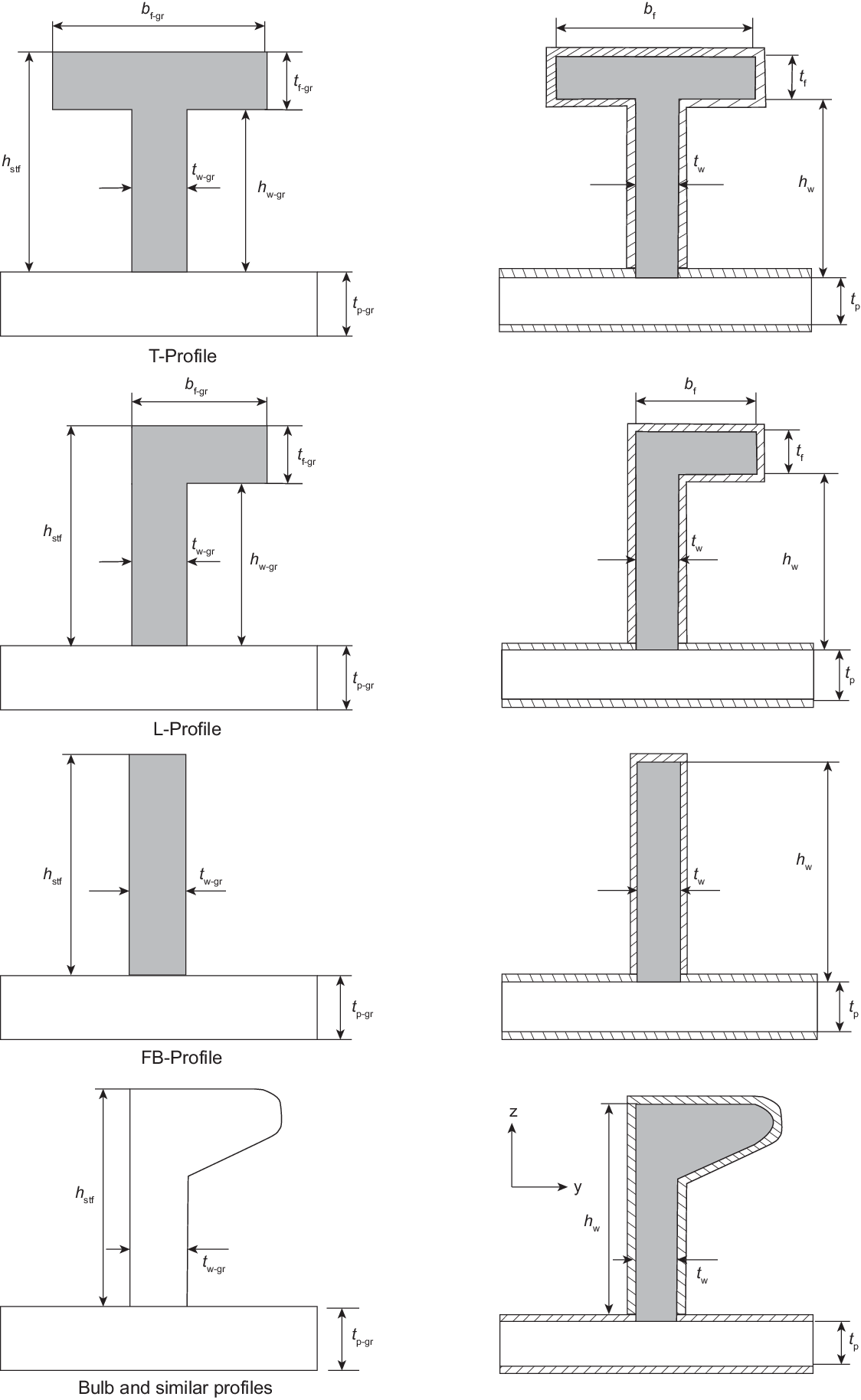
Figure 8.16.1 Net sectional properties of
supporting members
16.4 Permissible still water bending moments and shear forces
16.4.1 The permissible still water bending moments,
Ms in kNm, and still water shear
forces, Qs in kNm, are to be
calculated at each section along the ship’s length
for design loading conditions as specified in Pt 3, Ch 4, 5.3 Design still water bending moments.
16.5 Hull moment of inertia
16.6 Design vertical wave bending moments
16.6.1 The appropriate hogging or sagging design hull vertical wave bending
moment, at any position along the ship, may be taken as follows:
|
Mw |
= |
 |
Where:
f1 is the ship service factor, to be taken as 0,85
CW and C3 are given in Pt 4, Ch 8, 16.2 Symbols 16.2.1 and Pt 4, Ch 8, 16.6 Design vertical wave bending moments 16.6.2 respectively
f2 is the hogging,ffH , or the sagging,
ffS correction factor
ffH is the hogging (positive) moment correction factor and is to be
taken as:
|
ffH |
= |
 not to be taken greater than 1,1 not to be taken greater than 1,1 |
ffS is the sagging (negative) moment correction factor and is to be
taken as:
|
ffS |
= |
 , not to be taken less than 1,0 , not to be taken less than 1,0 |
fbow and Kf are given in Pt 4, Ch 8, 16.6 Design vertical wave bending moments 16.6.3 and Pt 4, Ch 8, 16.6 Design vertical wave bending moments 16.6.4 respectively
Kf is given in Pt 4, Ch 8, 16.6 Design vertical wave bending moments 16.6.4
B and L are given in Pt 4, Ch 8, 1.5 Symbols and definitions
16.6.2 The wave parameter, C3, is to be taken as:
|
C3 |
= |
 |
|
C3 |
= |
 |
Where:
|
L4 |
= |
 |
16.6.3 The bow flare shape, fbow coefficient is to be taken as:
|
fbow |
= |
 |
Where:
- ADK is the projected area in the horizontal
plane of the uppermost deck, in m2, including the forecastle
deck, if any, forward of 0,8L from the AP, see also
Figure 8.16.2 Projected area ADK and vertical distance zf. Any other structures, e.g. plated bulwark,
are to be excluded.
- AWLis the waterplane area, in m2, at draught
T, forward of 0,8L from the AP
- zf is the vertical distance, in m, from the
waterline at draught T, to the uppermost deck at side (or forecastle deck),
measured at the FP, see also
Figure 8.16.2 Projected area ADK and vertical distance zf. Any other structures, e.g. plated bulwark,
are to be excluded.
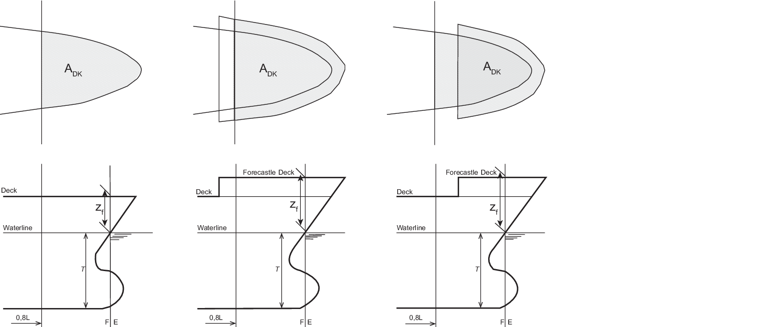
Figure 8.16.2 Projected area ADK and vertical distance zf
16.6.4 The distribution of the vertical wave bending moment, Kf , is to be
taken as:
- Hogging (positive) moments, see also Figure 8.16.3 Distribution of vertical wave bending moment Mw along the ship
length
|
Kf |
= |
0 at aft end of L |
| = |
0,15 at 0,1 L
|
| = |
1,0 between 0,35 L and 0,55 L
|
| = |
0,25 at 0,8 L
|
| = |
0 at forward end of L
|
- Sagging (negative) moments, see also Fig 8.16.3
|
Kf |
= |
0 at aft end of L |
| = |
-1,0 between 0,35 L and 0,6 L |
| = |
0 at forward end of L |
Intermediate values are to be obtained by linear interpolation.
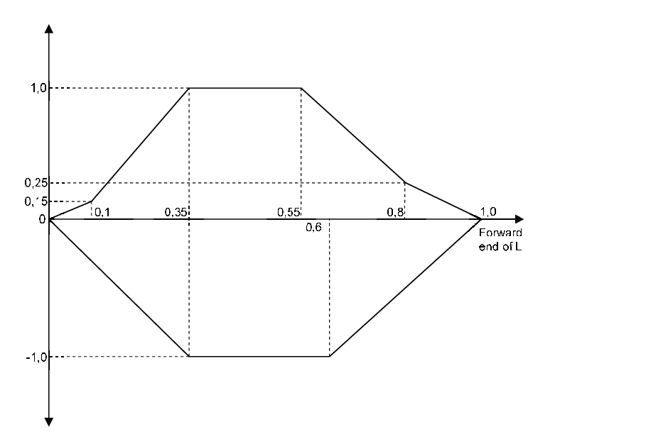
Figure 8.16.3 Distribution of vertical wave bending moment Mw along the ship
length
16.7 Design vertical wave shear force
16.7.1 The design hull wave shear force, Qw , at any position
along the ship is to be taken as:
|
Qw |
= |
 |
Where:
|
f1 |
= |
ship service factor, to be taken as 0,85 |
Cw, C3 and Kf are
defined in Pt 4, Ch 8, 16.2 Symbols, Pt 4, Ch 8, 16.7 Design vertical wave shear force 16.7.2
and Pt 4, Ch 8, 16.7 Design vertical wave shear force 16.7.3
respectively B and L are given in Pt 4, Ch 8, 1.5 Symbols and definitions 1.5.1
16.7.2 The wave parameter, C3, is to be taken as:
|
C3 |
= |
 |
|
C3 |
= |
 |
Where:
|
L4 |
= |
 |
16.7.3 The distribution of the wave shear force, Kf , is to
be taken as follows, see also Figure 8.16.4 Distribution of vertical shear force Qw along the ship
length.
- Positive shear force
|
Kf |
= |
0 at aft end of L |
|
Kf |
= |
5,2(0,3 + 0,7 ffH) between 0,2
L and 0,3 L |
|
Kf |
= |
4,0 between 0,4 L and 0,55 L |
|
Kf |
= |
5,7 (0,25 + 0,75 ffS) between
0,65 L and 0,85 L |
|
Kf |
= |
0 at forward end of L |
- Negative shear force
|
Kf |
= |
–1,3(0,3 + 0,7 ffS) at aft end of
L |
|
Kf |
= |
–5,2(0,3 + 0,7 ffS) between 0,15
L and 0,3 L |
|
Kf |
= |
-4,0 between 0,4 L and 0,5 L |
|
Kf |
= |
-5,7 ffH between 0,6 L and
0,75 L |
|
Kf |
= |
0 at forward end of L |
Intermediate values of Kf to be obtained by linear
interpolation.
ffH and ffS are as defined in Pt 4, Ch 8, 16.6 Design vertical wave bending moments 16.6.1.
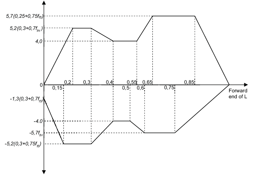
Figure 8.16.4 Distribution of vertical shear force Qw along the ship
length
16.8 Permissible hull girder stresses
16.8.1 The permissible combined (still water plus wave) stress for hull vertical
bending, σ , is given by:
|
σ |
= |
 |
16.8.2 The permissible shear stress, τ , is given by:
|
τ |
= |
 |
16.9 Hull girder stresses
Where:
Qw and Qs are defined in Table 8.16.3 Combination of still water and wave bending moments and shear forces.
γ s, γ w are partial safety factors to be taken as:
-
qv is calculated in accordance with the ShipRight
Procedure Additional calculation procedures for longitundinal
strength
Table 8.16.3 Combination of still water and wave bending moments and shear forces
| Load
case
|
Bending moment
|
Shear force
|
| Still water,
Ms
|
Wave,
Mw
|
Location,
x
|
Still water,
Qs
|
Wave,
Qw
|
| Hogging
|
M
smax
|
M
wmax
|

|
Qsmax
|
Qwmax
|

|
Qsmin
|
Qwmin
|
| Sagging
|
M
smin
|
M
wmin
|

|
Qsmin
|
Qwmin
|

|
Qsmax
|
Qwmax
|
| Symbols
|
| Msmax = positive still water bending moment
at the cross-section under consideration
|
| Msmin = negative still water bending moment
at the cross-section under consideration
|
| Mwmax = wave bending moment at the
cross-section under consideration, to be taken as the positive value
of Mw as defined in Pt 4, Ch 8, 16.6 Design vertical wave bending moments 16.6.1
|
| Mwmin = wave bending moment at the
cross-section under consideration, to be taken as the negative value
of Mw as defined in Pt 4, Ch 8, 16.6 Design vertical wave bending moments 16.6.1
|
| Qsmax = positive still water shear force at
the cross-section under consideration
|
| Qsmin = negative still water shear force at
the cross-section under consideration taken as
|
| Qwmax = maximum value of the wave shear force
at the cross-section under consideration, to be taken as the
positive value of Qw as defined in Pt 4, Ch 8, 16.7 Design vertical wave shear force 16.7.1
|
| Qwmin = minimum value of the wave shear force
at the cross-section under consideration, to be taken as the
negative value of Qw as defined in Pt 4, Ch 8, 16.7 Design vertical wave shear force 16.7.1
|
| x =
longitudinal coordinate or a location under consideration
|
16.10 Buckling strength assessment
16.10.1 The following requirements apply to plate panels and longitudinal
stiffeners subject to hull girder bending and shear stresses.
16.10.2 The acceptance criteria for the buckling assessment are defined as follows:
Where:
- ηact is the maximum utilisation factor
16.10.3 The utilisation factor, η act, is given by:
|
ηact |
= |
 |
16.10.4 Failure state limits are defined in ShipRight Procedure Additional
calculation procedures for longitudinal strength for the following items:
- Elementary plate panels
- Overall stiffened panels
- Longitudinal stiffeners
Each failure limit state is defined by an equation and, γc, is to be
determined such that it satisfies the equation.
16.10.6 The following two stress combinations are to be considered for each of
the load cases defined in Pt 4, Ch 8, 16.9 Hull girder stresses 16.9.1. The stresses are
to be derived at the load calculation points defined in Pt 4, Ch 8, 16.10 Buckling strength assessment 16.10.7 and Pt 4, Ch 8, 16.10 Buckling strength assessment 16.10.8
- Longitudinal framing
Stress combination 1
with:
|
σx |
= |
σHG |
|
σy |
= |
0 |
|
τ |
= |
0,7 τHG |
Stress combination 2 with:
|
σx |
= |
0,7 σHG |
|
σy |
= |
0 |
|
τ |
= |
τHG |
- Transverse framing
Stress combination 1 with:
|
σx |
= |
0 |
|
σy |
= |
σHG |
|
τ |
= |
0,7 τHG |
Stress combination 2 with:
|
σx |
= |
0 |
|
σy |
= |
0,7 σHG |
|
τ |
= |
τHG |
16.10.8 The hull girder stresses for longitudinal stiffeners are to be calculated at the
following load calculation points:
- At the mid length of the stiffener under consideration
- At the intersection point between the stiffener and its attached
plate
Table 8.16.4 Load calculation points
(LCP) for plate buckling assessment
| LCP coordinates
|
Hull girder bending stress
|
Hull girder shear stress
|
| x coordinate
|
Mid length of the elementary
plate panel (EPP)
|
| y coordinate
|
Both upper and lower ends of the EPP, points A1 and
A2 in Figure 8.16.
|
Mid-point of EPP, point B in Figure 8.16.
|
| z coordinate
|
Distance from baseline to
load calculation point
|
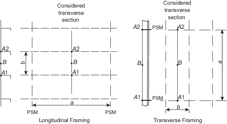
Figure 8.16.6 Load calculation points
for plate buckling
16.11 Hull girder ultimate strength
16.11.1 The hull girder ultimate strength assessment is to be carried out for
ships with a length L greater than or equal to 150 m.
16.11.3 The hull girder ultimate bending capacity,MU , is
defined as the maximum bending moment capacity of the hull girder beyond which the
hull structure collapses.
16.11.5 The ultimate bending moment capacities of a hull girder transverse
section, in hogging and sagging conditions, are defined as the maximum values of the
curve of bending moment M versus the curvature Χ of the transverse
section considered
16.11.6 The hull girder ultimate bending capacity, MU, is to
be calculated using the incremental-iterative method as given in Chapter 4 of
ShipRight Procedure Additional calculation procedures for longitudinal
strength.
16.11.7 The vertical hull girder bending moment, M in hogging and sagging conditions,
to be considered in the ultimate strength check is to be taken as:
Where:
|
Ms |
= |
permissible still water bending moment, in kNm, as defined
in Pt 4, Ch 8, 16.4 Permissible still water bending moments and shear forces 16.4.1 |
|
Mw |
= |
vertical wave bending moment, in kNm, as defined in Pt 4, Ch 8, 16.6 Design vertical wave bending moments 16.6.1
|
|
γs
|
= |
partial safety factor for the still water bending moment, to be taken as
1,0 |
|
γw |
= |
partial safety factor for the vertical wave bending moment, to be taken
as 1,2 |
16.11.8 The hull girder ultimate bending capacity at any hull transverse section is to
satisfy the following criteria:
Where:
|
M |
= |
vertical bending moment, in kNm, as defined in Pt 4, Ch 8, 16.11 Hull girder ultimate strength 16.11.7 |
|
MU |
= |
hull girder ultimate bending moment capacity, in kNm, as
defined in Pt 4, Ch 8, 16.11 Hull girder ultimate strength 16.11.6
|
|
γM |
= |
partial safety factor covering material, geometric and strength
prediction uncertainties, to be taken as 1,05 |
|
γDB |
= |
partial safety factor covering the effect of double bottom bending, to
be taken as:
|
γDB |
= |
1,15 for hogging condition |
|
γDB |
= |
1,0 for sagging condition |
|
- For cross-sections where the double bottom breadth of the inner bottom is
less than that at amidships or where the double bottom structure differs
from that at amidships (e.g. engine room sections), the factor,
γDB, for the hogging condition may be specially
considered.
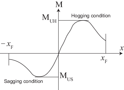
Figure 8.16.7 Bending moment M versus curvature Χ
|