
Section
4 Global strength assessment
4.1 General
4.1.1 The verification of the stress level, buckling capability and deflection of the dock
gate’s primary members is to be assessed by direct calculation.
4.1.2 In general, the direct calculation is to be based on a three-dimensional (3-D) FEA
carried out in accordance with the procedures contained in this Section. Where
alternative procedures are proposed, these are to be agreed with LR before
commencement.
4.1.4 A detailed report of the calculations is to be submitted and is to
include the following information. The report must show compliance with the
specified structural design criteria given in Pt 2, Ch 2, 4.8 Structural design criteria.
- list of plans used, including dates and versions;
- detailed description of structural model, including all
modelling assumptions;
- plots to demonstrate correct structural modelling and
assigned properties;
- details of material properties used for all components;
- details of boundary conditions including seal stiffness
properties;
- details of applied loading and confirmation that individual
and total applied loads are correct;
- details of boundary support forces and moments;
- plots and results that demonstrate the correct behaviour of
the structural model to the applied loads;
- summaries and plots of global and local deflections;
- summaries and sufficient plots of von Mises, directional and
shear stresses to demonstrate that the design criteria are not exceeded in any
manner;
- plate buckling analysis and results;
- tabulated results showing compliance, or otherwise, with the
design criteria; and
- proposed amendments to structure, where necessary, including
revised assessment of stresses and buckling properties.
4.2 Type of analysis
4.2.1 Linear elastic methods capable of accounting for the following are to be used:
- global shear lag effects;
- asymmetry between the supports and the dock gate
centreline;
- global deformation of the dock gate; and
- rotation/deformation at the boundaries.
4.2.2 Non-linear methods need not normally be employed; however, if they are
used then the following aspects are to be considered:
- Loss of stiffness/strength in the event of severe buckling;
and
- Loss of contact at the boundaries.
Non-linear methods are to be agreed with LR prior to the commencement of any
investigations.
4.3 Net scantling approach
4.3.1 The global FEM strength assessment is to be carried out based on net
scantlings, i.e. an appropriate corrosion addition, tc, see
Pt 2, Ch 2, 4.4 Corrosion additions, is to be
deducted from the gross offered thickness.
4.3.2 The gross offered thickness, t, is the gross thickness provided at the
newbuilding stage, which is obtained by deducting any thickness for voluntary
addition from the as-built thickness, i.e. any additional thickness specified by the
Owner or builder is not to be included when considering compliance with the
Rules.
4.3.3 The strength assessment methods prescribed are to be assessed by
applying the corrosion reduction given in Table 2.4.1 Assessment for
corrosion to the
offered gross scantlings where half of the applied corrosion addition is to be
deducted from both sides of the structural members being considered.
Table 2.4.1 Assessment for
corrosion
| Structural
requirement
|
Property/analysis
type
|
Applied corrosion
addition
|
| Strength
assessment by FEM
|
Tanks
|
0,5
tc
|
| Buckling capacity
|
tc
|
| Fine mesh
|
0,5
tc
|
4.3.4 The net sectional properties of stiffeners are obtained by deducting half the applied
corrosion addition from each surface of the profile cross-section.
4.4 Corrosion additions
4.4.2 A reserve thickness, tres, of 0,5 mm is also to be included.
4.4.3 The total corrosion addition, in mm, for both sides of the structural member is
obtained by the following formula:
4.4.4 For an internal member within a given compartment, the total corrosion addition, in
mm, is obtained from the following formula:
Table 2.4.2 Corrosion addition for one side of a structural member
| Compartment type
|
Structural member
|
tc1 or tc2
|
| Ballast water and flood water
|
All members
|
1,0
|
| Exposed vehicle deck
|
Deck plating
|
3,5
|
| Exposed to atmosphere
|
All members
|
1,0
|
| Exposed to sea water
|
All members
|
1,0
|
| Void spaces
|
Spaces not normally accessed, e.g.
access only via bolted manhole openings, pipe tunnels, inner
surface of stool space
|
0,5
|
| Dry spaces
|
Internals of machinery spaces, pump
room, etc.
|
0,5
|
| Other tanks and spaces
|
All members
|
0,5
|
4.5 Modelling
4.5.1 A 3-D FE model of the complete dock gate is to be used to assess the primary
structure.
4.5.2 The proposed scantlings, excluding any Owner’s extras, are to be used throughout the
model. The selected size and type of elements are to provide a satisfactory
representation of the deflection and stress distributions within the model.
4.5.3 In general, the plate element mesh is to follow the primary stiffening arrangement.
The minimum mesh size requirements are:
- transversely, one element between every longitudinal
stiffener;
- longitudinally, three or more elements between web
frames;
- vertically, one element between every stiffener; and
- three or more elements over the depth of floors, side
transverses, vertical webs and horizontal stringers of bulkheads.
The mesh density of the side shell plating in way of the side frames is to be similar
to those adjacent to the side shell plating.
4.5.4 Secondary stiffening members are to be modelled using line elements positioned in the
plane of the plating having axial and bending properties (bars). The bar elements
are to have:
- a cross-sectional area representing the stiffener area,
excluding the area of attached plating; and
- bending properties representing the combined plating and
stiffener inertia.
4.5.6 In general, the use of triangular plate elements is to be kept to a minimum. Where
possible, they are to be avoided in areas where there are likely to be high stresses
or a high stress gradient. These include areas:
- in way of lightening/access holes; and
- adjacent to brackets, knuckles or structural
discontinuities.
4.5.7 Access openings, lightening holes, etc. in primary structures are to be
represented in areas of interest, e.g. where they are of sufficient size to
influence member stiffness. Additional mesh refinement could be necessary to model
these openings, but it could be sufficient to represent the effects of the opening
by deleting the appropriate elements.
4.5.8 The lightweight of the dock gate is to be represented in the model.
4.5.9 Solid ballast shall be included in the model in its correct position and
can be modelled as lumped masses attached to appropriate model nodes provided that
the load is appropriately distributed to local nodes. Ballast which is moveable such
as pig iron is to be assumed to be located in its most unfavourable position.
4.5.10 The effects of added mass (i.e. entrained water located outside the dock gate, but
which is considered to move with the dock gate) are to be considered using a method
which is to be agreed with LR.
4.5.11 A grillage model can be used subject to agreement with LR.
Table 2.4.3 Line element effective
cross-section area
| Structure represented by
element
|
Effective area, Ae
|
| Primary
member face bars
|
Symmetrical
|
Ae = 100%
An
|
| Asymmetrical
|
Ae = 100%
An
|
| Curved
bracket face bars (continuous)
|
Symmetrical
|
See
Figure 2.4.1 Effective area of face
bars
|
| Asymmetrical
|
| Straight
bracket face bars (discontinuous)
|
Symmetrical
|
Symmetrical
|
Ae = 100%
An
|
| Asymmetrical
|
Asymmetrical
|
Ae = 60%
An
|
| Straight
bracket face bars (continuous around toe curvature)
|
Straight portion
|
Symmetrical
|
Ae = 100%
An
|
| Asymmetrical
|
Ae = 60%
An
|
| Curved portion
|
Symmetrical
|
See
Figure 2.4.1 Effective area of face
bars
|
| Asymmetrical
|
| Web
stiffeners – sniped both ends
|
Flat bars
|
Ae = 20% of stiffener
area
|
| Other sections
|
|
| Web
stiffeners – sniped one end, connected other end
|
Flat bars
|
Ae = 75% of stiffener
area
|
| Other sections
|
|
| Note Consistent
units to be used throughout
|
| Symbols
|
| A
|
= cross-section area of
stiffener and associated plating
|
| An
|
= average face bar area
over length of line element
|
| Ap
|
= cross-section area of
associated plating
|
| I
|
= cross-section area of
associated plating
|
| Y0
|
= moment of inertia of
stiffener and associated plating
|
| r
|
= radius of gyration

|
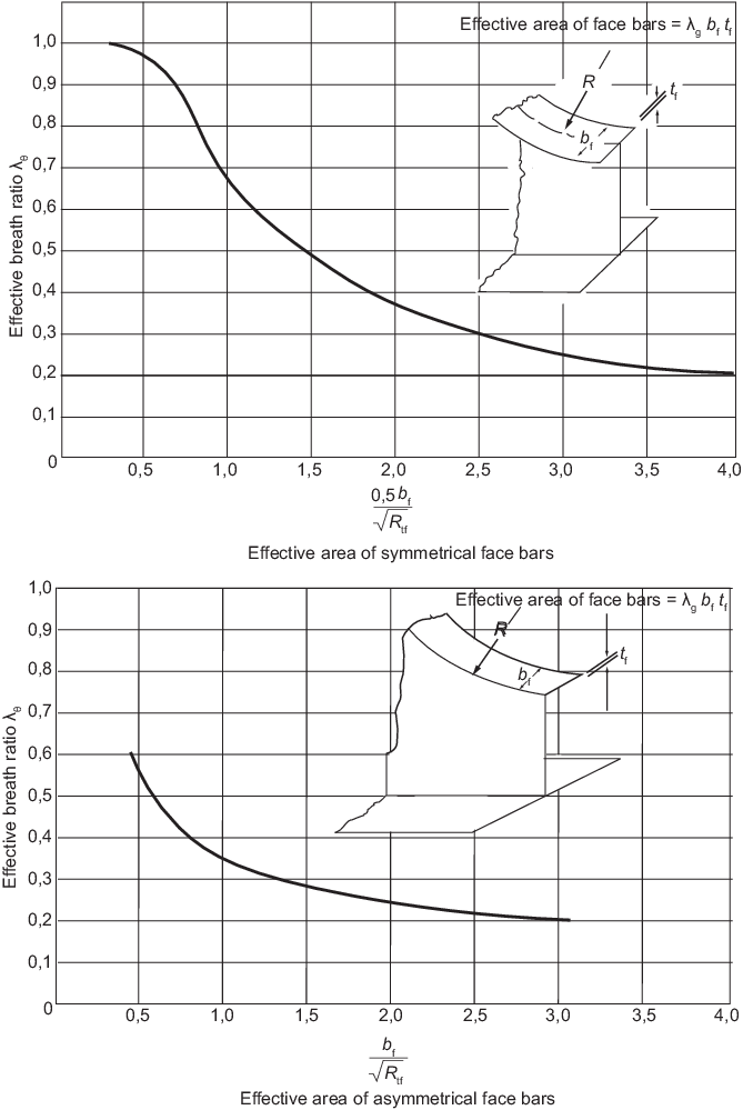
Figure 2.4.1 Effective area of face
bars
4.6 Boundary conditions
4.6.1 In general, the dock gate will be supported vertically at the sill base and laterally
on two sides. The support will be provided via a soft seal and the stiffness of the
seals is to be included in the analysis.
4.6.2 The stiffness and damping characteristics of the seals are to be provided
by the gate designer or seal manufacturer together with how these properties can
vary around the dock gate perimeter when different seal stiffnesses are specified by
the designer. The stiffnesses of seals employed in the structural models are to be
consistent with the direction of displacement of the seals, i.e. for translations
perpendicular to the compression axis of the seal, shear stiffness of the seal is to
be modelled.
4.6.3 The lateral sway of the dock walls should not impose in-plane forces on the dock gate
other than those transferred via seal shear stiffness and friction. If there is
insufficient edge clearance between the dock walls and the dock gate to ensure that
this condition is met, then the interaction between the walls and the dock gate is
to be addressed.
4.7 Application of loads
4.7.1 The load scenarios given in Pt 2, Ch 2, 4.7 Application of loads 4.7.2 to Pt 2, Ch 2, 4.7 Application of loads 4.7.5 are to be
considered where the applied loads are to be taken as the loads given in Pt 2, Ch 2, 2.1 General (as appropriate) are to be
multiplied by the load factors given in Pt 2, Ch 2, 4.7 Application of loads 4.7.6 and Pt 2, Ch 2, 4.7 Application of loads 4.7.7.
4.7.2 The following load scenarios are to be considered:
- normal operating; and
- extreme.
4.7.3 The normal operating scenarios comprise the following:
- lightweight only;
- lightweight + hydrostatic (operating);
- lightweight + hydrostatic (operating) + wind;
- lightweight + deck loads + hydrostatic (operating);
- lightweight + deck loads + hydrostatic (operating) +
wind;
- lightweight + internal loads;
- lightweight + hydrostatic (operating) + internal loads +
deck loads + wind; and
- lightweight + air pressure test load.
4.7.4 The extreme scenarios comprise the following:
- lightweight + deck loads + hydrostatic (maximum credible).
4.7.5 Other load scenarios can be considered at the request of the Owner.
4.7.7 Consideration can be given to reducing the partial load factors for secondary loads
in accordance with BS 6349 Maritime Works. Note that hydrostatic loading is
considered to be a primary load.
Table 2.4.4 Partial load factors
| Load
|
Load scenario, see
Pt 2, Ch 2, 4.7 Application of loads 4.7.2
|
| Normal
|
Extreme
|
| Lightweight
|
1,35
|
1,0
|
| Hydrostatic - maximum credible
level
|
N/A
|
1,35
|
| Hydrostatic - otherwise
|
1,5
|
N/A
|
| Deck loading
|
1,5
|
1,0
|
| Wind loading
|
1,35
|
N/A
|
| Internal loads
|
1,0
|
N/A
|
| Test loads
|
1,0
|
N/A
|
4.8 Structural design criteria
4.8.1 The stresses resulting from the application of all load scenarios are not to exceed
the following:
- combined stress – 1,0 σo;
- direct stress – 0,9 σo;
- shear stress – 0,5 σo.
σo is defined in Pt 2, Ch 2, 1.4 Materials.
4.8.2 Stress criteria are based on the coarse mesh described in Pt 2, Ch 2, 4.5 Modelling 4.5.4. If a finer mesh is used,
then stress can be averaged over an area equal to the size of the coarse mesh
element in way of the structure being considered. The averaging is to be based only
on elements with their boundary located within the desired area. Stress averaging is
not to be carried out across structural discontinuity or abutting structure.
4.8.3 For all load scenarios, except for the extreme load scenarios, plate buckling is to
be investigated for all areas of primary structure. The factor against buckling is
to be taken as 1,1.
4.8.4 Panel buckling calculations are to be based on the net thickness of the plating.
4.8.5 In general, the applied stresses for buckling assessment are to be increased by a
factor equal to the original thickness divided by the thickness after corrosion.
4.8.6 When the calculated elastic critical buckling stress, σ c,
exceeds 50 per cent of the specified minimum yield stress, then the buckling stress
is to be adjusted for the effects of plasticity using the Johnson-Ostenfeld
correction formula, given below:
- when σc≤0,5σo
σcr = σo
- when σc>0,5σo

where
|
σcr |
= |
the critical buckling stress corrected for plasticity
effects, in N/mm2 |
|
σc |
= |
the elastic critical buckling stress, in
N/mm2 |
σo is defined in Pt 2, Ch 2, 1.4 Materials
4.8.7 Deflections of individual panels under lateral hydrostatic loading shall not exceed
1/200 of the principal panel dimension.
4.8.8 Deflections of any stiffener supporting plate subjected to hydrostatic loading shall
not exceed 1/200 of the stiffener span.
4.9 Additional requirements for floating dock gates
|