
Section
8 Vibration problems and solutions
8.1 Main Engine
8.1.1 As mentioned in Ch 1, 6.2 Machinery 6.2.1, slow speed Diesel engines often feature significant
dynamic forces at several orders. Hence, comments in this section relate to this
type of engine. Engine manufacturers normally make recommendations regarding
vibration countermeasures for fitting to their engines, if appropriate.
8.1.2 Engine excitation moments at first and second order can be resonant with the lower
hull natural frequencies of large cargo ships, which can be a problem if the
excitation magnitude is large and the engine is located around a node point of a
corresponding vibration mode shape. First order moments feature in the horizontal
and vertical sense, and static balance weights can be used to reduce moments in one
direction at the expense of the other, depending on the potential problem. Second
order moments are in the vertical sense only, and these can be neutralised by
balancers fitted at the aft and forward end of the engine that consist of a system
of rotating weights driven by the engine.
8.1.3 Some engines have a significant H-moment (sideways rocking) at firing order, for
which the engine manufacturers may recommend transverse top bracing. These stays may
be of the friction pad or hydraulic type, and they should be attached to substantial
ship structure in order to be effective. They essentially alter the dynamic
behaviour of the engine together with the ship structure in way of the engine room.
Transverse top bracing may also be recommended for engines with large X-moments
(twisting).
8.1.4 Troublesome H- and X-moments may also be reduced by changed the firing order of the
engine, though this may not always be possible due to other restrictions, such as
torsional stress limits on the shaft and certification of the engine for emissions
etc.
8.1.5 In ships with more than one engine, phasing of the engines’ firing has been used
effectively to reduce certain orders that were problematic. The fundamental concept
is the same as that of using a compensator. The systems typically require relatively
inexpensive additional instrumentation to be fitted to allow the ship’s engineers to
read the engines’ relative phasing.
8.2 Propeller Shaft
8.2.1 As mentioned in Ch 1, 6.2 Machinery 6.2.5, dynamic forces in the propulsion shafting system can
be transmitted into the ship structure via the thrust block, primarily at engine
firing frequency.
8.2.2 The magnitude of the dynamic forces depends upon the design of the shafting system;
most notably the shaft diameter in relation to the torsional natural frequency,
together with the engine characteristics. The ‘thin shaft’ design is usually
employed, where the fundamental torsional natural frequency of the shaft is below
engine firing frequency at operational RPM, and this leads to a ‘barred speed range’
of RPM in way of this resonance, whereby the ship is not to operate continuously
within this range in order to avoid excessive vibration. The ‘thick shaft’ design
has sometimes been used in the past, where the fundamental torsional natural
frequency of the shaft is above engine firing frequency at operational RPM, in order
to avoid a barred speed range. However, it can mean operating on the rising flank of
this resonance, leading to unfavourable vibration responses, so it is not usually
recommended.
8.2.3 Axial and torsional dampers are often a standard fitting for slow speed Diesel
engines, at the forward end of the engine crankshaft.
8.3 Propeller
8.3.1 Vibration problems resulting from propeller excitation are, in some cases, the result
of excessive excitation levels; and, in others, a result of resonances of structural
natural frequencies with propeller excitation frequencies. A reduction in propeller
excitation will be beneficial in both cases.
8.3.2 Propeller dynamic forces depend upon propeller design, loading and flow conditions
into the propeller (wake).
8.3.3 The characteristics of the wake are primarily determined by the after-body design.
Further, in some cases, the wake has been adversely affected by disturbances, such
as cooling water discharges on the hull forward of the propeller. The wake is
usually assessed by model measurements, though CFD is expected to have increasing
application in this regard, and also leads to prediction of cavitation extent on
propeller blades.
8.3.4 As mentioned in Ch 1, 6.3 Propulsors 6.3.1, propeller excitation may initially be evaluated by
calculations or model measurements. As an approximate guideline for cargo ships, at
propeller blade frequency, hull surface pressures above the propeller in excess of 8
kilopascals (kPa) would have a high probability of producing vibration problems,
irrespective of notable structural resonances. Levels in the region of 4 to 8 kPa
would probably lead to problems if there are significant structural resonances.
Pressures of less than 4 kPa would be a favourable indication in most cases. In
relation to twice the propeller blade frequency, the guideline would be half of the
pressures stated for blade frequency. A further reduction of amplitudes is required
for higher harmonics.
8.3.5 For passenger ships, which have more demanding vibration criteria, these guideline
values typically could be halved, or even further reduced, for some mega yachts.
8.3.6 As may be discerned from the hull surface pressures mentioned above for blade and for
twice the blade frequency (that is, first and second blade harmonics), it is
expected that magnitudes should decrease in a similar manner for increasing
harmonics. If that is not the case, problems may be indicated for the higher orders
in relation to propeller noise and excitation of local panels of structure close to
the propeller. In relation to the latter, it is generally not feasible to deal with
such problems by alteration of local structure to avoid resonances, in view of the
spread of panel natural frequencies and the broad frequency band of the
excitation.
8.3.7 High propeller excitation levels usually imply high incidence of
cavitation. Improvements can be effected by alterations to the propeller design or
modification of the wake. The latter is more easily effected and can be investigated
using CFD, which for example may lead to a recommendation to fit a flow alteration
device such as a vortex generator, usually of elongated pyramid shape, to the hull
forward of the propeller for modifying the wake pattern. A typical example is shown
in Figure 1.8.1 An example of a vortex
generator fitted to the hull, forward of the propeller, where the right hand side of the
picture is forward.
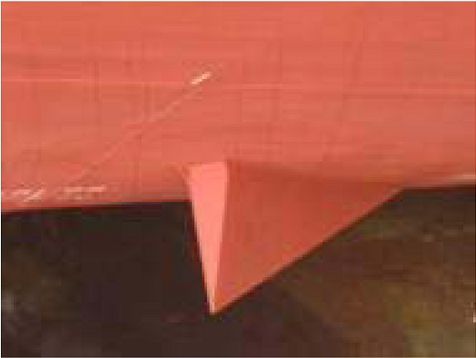
Figure 1.8.1 An example of a vortex
generator fitted to the hull, forward of the propeller
8.3.8 In a few past cases of problematical propeller excitation in service, air injection
into the top blade region has usefully been employed. However, such a system is
expensive to fit and maintain.
8.4 Hull
8.4.1 In general, it is not feasible to address overall hull vibration
problems by structural alterations. Hence, remedial measures would comprise
reduction in excitation levels, such as through balancing of the main engine. The
lowest hull natural frequency is normally the 2-node vertical mode (as shown in
Figure 1.8.2 FE analysis result showing the 2-node vertical vibration mode) or 1-node torsional mode. For the
super long ships, this is often in the region of 0.5 Hz.
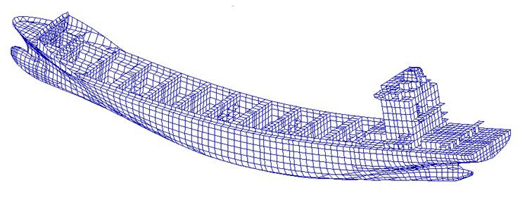
Figure 1.8.2 FE analysis result showing the 2-node vertical vibration mode
8.4.2 As mentioned in Ch 1, 8.1 Main Engine, slow speed Diesel main engines can cause significant
hull vibration, normally occurring at a resonance with the fundamental natural
frequencies of the hull. If such a problem were indicated, then the usual solution
would be the prescribed balancing for the engine. This requirement is shown as an
example in Figure 1.8.2 FE analysis result showing the 2-node vertical vibration mode (4-node vertical mode). The
engine is below the superstructure, and thereby unfavourably located for vertical
moments, as it is at a node point.
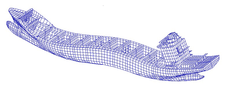
Figure 1.8.3 FE analysis result showing the 4-node vertical vibration mode
8.4.3 Unfortunately, cases have occurred where both a vertical and a horizontal hull mode
were in the operational speed range and were excessively excited by the first order
moment of the engine. In these cases, balancing to reduce either the horizontal or
vertical engine first order moment may be undertaken, and a compensator fitted to
counter the remaining out-of-balance engine first order moment.
8.4.4 In relation to high propeller excitation, this can sometimes bring about
significant vertical vibration at the aft end of the hull, particularly when there
is resonance between propeller blade frequency and a vertical aft end vibration mode
– often known as a ‘fan-tail’ mode (see
Figure 1.8.3 FE analysis result showing the 4-node vertical vibration mode). Local structural alterations,
particularly regarding longitudinal bulkheads in the aft end of the hull may be
feasible at an early design stage; otherwise attention can be given to propeller
excitation or the number of blades. It should be noted that the aft end of the hull
in cargo ships does not contain permanently occupied spaces that are subject to
habitability standards.
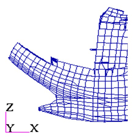
Figure 1.8.4 FE analysis result showing ‘Fan-Tail’ effect
8.4.5 In Ch 1, 6.4 Sea Waves 6.4.2, it was stated that sea waves can cause uncomfortable
vibration by way of slamming impacts at the ends of a ship. Slamming forward can, of
course, be addressed by a reduction in ship speed and/or a change of heading. For a
few passenger vessels with flat counter sterns at a particular height above the sea
surface, slamming impacts can cause unpleasant vibration in accommodation spaces
aft. However, this tends to be at low speed whilst manoeuvring, or stationary in
response to wave trains caused by passing vessels in port, since at higher speed a
stern wave usually immerses the flat counter stern. If such a relatively unusual
phenomenon is experienced in service, a known solution is to create an air cushion
under the flat counter stern by incorporating a ‘skirt’ arrangement around the area,
including internal diaphragms for strength purposes and air pressure relief
apertures.
8.5 ‘Tower Block’ Superstructure
8.5.1 Most cargo ships have crew accommodation and operating spaces placed in tower block
deckhouses at the aft end of the hull, for reasons of payload maximisation and cargo
handling. However, this is the least favourable location from the vibration point of
view, since it is above machinery compartments and close to the propeller.
Furthermore, the tower block is relatively high for visibility from the navigation
bridge.
8.5.2 Hull and superstructure vibration modes are invariably coupled, such that the
superstructure will follow hull vibration mode shapes. Notwithstanding, it has been
indicated many times by past practical experience that the fundamental longitudinal
natural frequency of a superstructure accommodation block is particularly important
to consider in relation to resonance avoidance. Relevant excitations in this respect
are firing frequency of slow speed Diesel engines and propeller blade frequency.
8.5.3 Excitation at engine firing frequency can arise from an H-moment and, although this
is a transverse moment, it can sometimes lead to some longitudinal vibration in the
superstructure. Further, as previously discussed for some cases, there can be a
longitudinal dynamic force imposed on the thrust block by the propulsion shafting
system.
8.5.4 The primary excitation at propeller blade frequency is usually the hull
surface force on the aft end of the hull above the propeller, as mentioned in Ch 1, 8.4 Hull, whereby vertical movement of the aft end in turn
brings about longitudinal displacement, by way of rotation for a tower block
superstructure that is located just forward of the aft end (see
Figure 1.8.5 Effect of propeller hull surface force on aft end and superstructure).
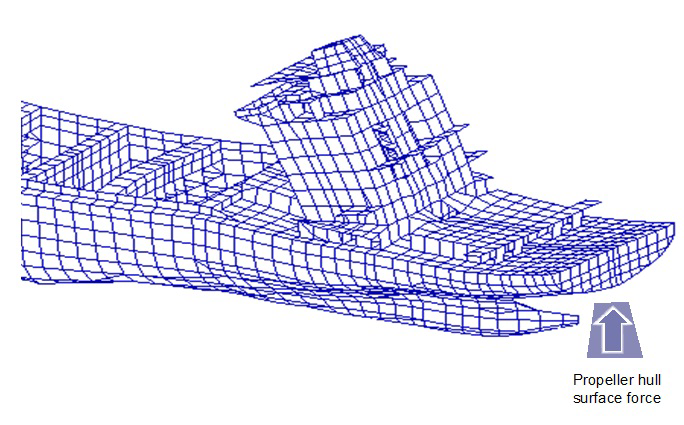
Figure 1.8.5 Effect of propeller hull surface force on aft end and superstructure
8.5.5 The fundamental longitudinal natural frequency of a tower block superstructure is
primarily determined by its height and length, followed by the configuration and
continuity of the longitudinal bulkheads, the support below the superstructure, and
the total mass including outfit. This natural frequency is often within the range 6
– 10 Hz.
8.5.6 Transverse vibration and torsional vibration of the superstructure,
which are mostly induced by the main engine H-type moment and X-type moment through
transverse top bracings and double bottom structure, may also occur during vessel
sea trials and in normal operation. Quite often, the natural frequencies of
transverse and torsional vibration modes are higher than those of longitudinal
modes, but they may vary in different cases.
8.5.7 If a problem of resonance with the fundamental longitudinal natural
frequency of a superstructure accommodation block is indicated, significant
structural alterations are not usually feasible or very effective, except for a
connection of the accommodation block to a separate funnel casing block for
applicable cases (at the expense of increased noise transmission). Normally,
structural alterations are also not feasible if resonance happens with transverse
and torsional vibration modes of the superstructure block.
8.5.8 The excitation source may be addressed to effect a solution. If it is the propeller,
attention can be given to excitation level and/or number of blades. If it is the
engine, attention can be given to the H-moment / X-moment by way of top bracing, or
damping devices for the propulsion shafting system, as appropriate.
8.5.9 Another possible solution that has been employed in some cases, usually post-trials,
is the fitting of a vibration compensator. This is a compact, electrically
controlled device incorporating rotating weights that can be installed on or near to
the navigation bridge. It can be adjusted for force magnitude, phase and frequency
to neutralise or reduce vibration. It tends to be more effective as a countermeasure
for machinery excited vibration, rather than from the propeller, as the former is of
a more consistent nature. Overall dimensions are within about one metre.
8.6 Bridge Wings
8.6.1 Cantilever bridge wings are often incorporated in cargo ships, for the purpose of
visibility along the ship sides.
8.6.2 Undesirable vibration levels can occur if there is resonance between the fundamental
longitudinal or vertical vibration modes of the bridge wings, with slow speed Diesel
engine firing frequency or propeller blade frequency in way of operating RPM and, to
a lesser extent, at twice the propeller blade frequency. Further, if there is
resonance between engine firing frequency or propeller blade frequency, together
with the fundamental longitudinal natural frequency of the tower block
superstructure and, simultaneously, the fundamental longitudinal natural frequency
of the bridge wings, the vibration responses can be very high.
8.6.3 Consequent to the above, it is recommended to calculate the fundamental
longitudinal and vertical vibration modes of the bridge wings at the design stage.
This can be part of a global ship vibration analysis, or a bridge wing local model
with suitable boundary conditions at the bridge side, to evaluate natural
frequencies. An example of such a model is shown in Figure 1.8.6 FE analysis result showing deflection of a cantilever bridge wing, indicating the fundamental
longitudinal mode.
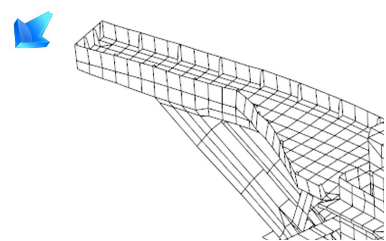
Figure 1.8.6 FE analysis result showing deflection of a cantilever bridge wing
8.6.4 If a problem is identified, it can be addressed by structural modifications, such as
struts or large brackets. An addition of mass at the ends of the bridge wings, in
order to lower their natural frequency, may also be feasible.
8.7 Large Span Deck Panels
8.7.1 These are of primary concern for accommodation areas in passenger ships, which are
subject to habitability standards. Vehicle decks in Ro Ro ships also feature, but
these would only be described as ‘occasionally occupied spaces’.
8.7.2 From the resonance avoidance point of view, it is possible to study
large span deck panels by using local models, subject to suitable boundary
conditions being arranged. However, they would normally be incorporated in a global
vibration analysis that would evaluate natural frequencies and vibration responses.
Typical large deck panel vibration modes are shown in Figure 1.8.7 FE analysis result showing a possible vibration mode of a large deck
panel.
8.7.3 The relevant excitation frequency would be the propeller blade frequency and the main
engine firing order frequency; thereby essentially being relevant for panels aft of
amidships. In order to avert possible undesirable vibration while occasionally using
manoeuvring devices, such as tunnel thrusters, resonance avoidance can be
implemented for large deck panels close to their locations.
8.7.4 Problems that are identified can be attended to by increasing numbers and/or
scantlings of primary girders/stiffeners or by introducing additional vertical
supports such as pillars or bulkheads with structural continuity below, subject to
arrangement considerations.
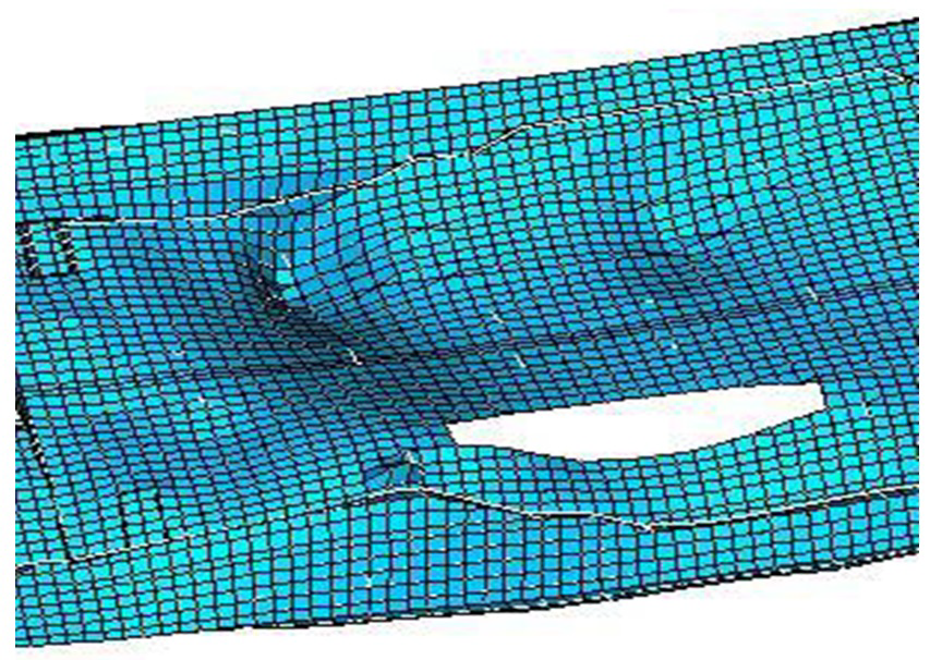
Figure 1.8.7 FE analysis result showing a possible vibration mode of a large deck
panel
8.8 Panels Local to Propeller
8.8.1 A resonance avoidance procedure should be applied for these, using analytical or
local finite element analysis to evaluate natural frequencies. For naval ships, this
is a LR class requirement.
8.8.2 Resonance avoidance should be implemented for aft peak panels, including the effect
of the added mass of fluid where appropriate, in order to avoid potential structural
damage. The relevant excitation frequencies for comparison are at propeller blade
and at twice the blade frequencies. The most common problem experienced in this
regard is cracking of fresh water tank bulkheads that are located in the aft
peak.
8.8.3 Resonance avoidance should be implemented for local panels in accommodation decks
close to propellers such as in tower block superstructures aft, including outfit
mass, where appropriate, in order to avoid potential infringement of habitability
standards. The relevant excitation frequency for comparison is propeller blade
frequency.
8.8.4 Problems are usually addressed by an increase to stiffening of the panels.
8.9 Masts on Naval Ships
8.9.1 Masts on naval ships often have sensitive surveillance equipment mounted on them, so
it is important to avoid resonance of fundamental mast natural frequencies with any
significant excitation frequencies that can be transmitted at the base of the
mast.
8.9.2 Hence, it is recommended to calculate the fundamental longitudinal and transverse
vibration modes of the masts at the design stage.
8.9.3 The masts should have substantial support arranged, so that local vertical vibration
is not an issue. This can be calculated as part of a global ship vibration analysis
or as a local analysis, using a model of the mast with suitable boundary conditions
applied. The structural design can then be amended, if unfavourable resonances are
indicated.
|