
Section
4 Sloshing and impact loads
4.1 Sloshing loads
4.1.1
Application.
- When the partial filling of tanks is contemplated in operating
conditions, the sloshing loads on tank boundaries are to be assessed in
accordance with the LR ShipRight Procedure for Ship Units. Full account is
to be taken of the operating requirements on station with regard to the
filling, transfer and export operations for cargo bulk storage tanks.
4.2 Bottom and bilge slamming loads
4.2.1
Application and limitations.
- The slamming loads in this Section apply to units with
 ≥ 0,7 and bottom slamming draught ≥0,01L and
≤0,045L. For operation at deeper draughts, the slamming loads
will need to be specially considered. ≥ 0,7 and bottom slamming draught ≥0,01L and
≤0,045L. For operation at deeper draughts, the slamming loads
will need to be specially considered.
- For units with unconventional bow or stern shapes or for harsh
service, the slamming loads, green sea loads and bow impact loads are to be
determined by a site-specific analysis. The analysis results are to be
verified by model tests.
4.2.2
Slamming pressure.
- The bottom slamming pressure,
 , is to be taken as the greater of: , is to be taken as the greater of:
 = =  130g 130g
 kN/m2 for empty tanks kN/m2 for empty tanks
 = =  130g 130g
 kN/m2 for full tanks kN/m2 for full tanks
where
|
g |
= |
acceleration due to gravity, 9,81
m/s2 |
 |
= |
longitudinal slamming distribution factor,
see
Pt 10, Ch 2, 4.2 Bottom and bilge slamming loads 4.2.2 and Figure 2.4.2 Longitudinal
distribution of slamming pressure at forward end |
| = |
0,5 at, and aft of, A.P. |
| = |
1,0 at [0,1 – 0,5 ( Cbl – 0,7)]
L from A.P. |
| = |
1,0 at [0,175 – 0,5 ( Cbl – 0,7)]
L from A.P. |
| = |
0,0 at 0,5L
|
| = |
1,0 at [0,175 – 0,5 ( – 0,7)] L from F.P. – 0,7)] L from F.P. |
| = |
1,0 at [0,1 – 0,5 ( – 0,7)] L from F.P. – 0,7)] L from F.P. |
| = |
0,5 at, and forward of, F.P. |
intermediate values to be obtained by linear
interpolation
 = environmental factor due to dynamic wave
pressure. = environmental factor due to dynamic wave
pressure.
 = block coefficient,  , as defined in Pt 10, Ch 2, 3.1 Symbols, but not to be taken
less than 0,7 or greater than 0,8
|
cslm-mt |
= |
slamming coefficient for empty tanks |
|
cslm-mt |
= |
 at aft end at aft end |
 |
= |
5,95 – 10,5  at forward end at forward end |
|
cslm-full |
= |
slamming coefficient for full tanks |
|
cslm-full |
= |
 at aft end at aft end |
|
cslm-full |
= |
5,95 – 10,5  at forward end at forward end |
|
C1 |
= |
0,0 for L ≤ 180 m |
| = |
– 0,0125  for L > 180 m for L > 180 m |
 |
= |
design slamming light load draught at A.P. with
tanks within the bottom and bilge slamming region empty, as
defined in Pt 10, Ch 2, 4.2 Bottom and bilge slamming loads 4.2.2, in metres |
 |
= |
design slamming light load draught at F.P. with
tanks within the bottom and bilge slamming region empty, as
defined in Pt 10, Ch 2, 4.2 Bottom and bilge slamming loads 4.2.2.(c), in metres |
 |
= |
design slamming light load draught at A.P. with
tanks within the bottom and bilge slamming region full, as
defined in Pt 10, Ch 2, 4.2 Bottom and bilge slamming loads 4.2.2, in metres |
 |
= |
design slamming light load draught at F.P. with
tanks within the bottom and bilge slamming region full, as
defined in Pt 10, Ch 2, 4.2 Bottom and bilge slamming loads 4.2.2.(d), in metres |
 |
= |
dynamic load coefficient, to be taken as 1,25 |
|
L |
= |
Rule length, in metres |
 |
= |
vertical distance from tank top to load point,
in metres. |
- The designer is to provide the design
slamming draughts
 and and  . .
- The design slamming draught at the F.P.,
 , is not to be greater than the minimum draught at the
F.P. indicated in the loading manual for all transit conditions wherein the
tanks within the bottom and bilge slamming region are empty. , is not to be greater than the minimum draught at the
F.P. indicated in the loading manual for all transit conditions wherein the
tanks within the bottom and bilge slamming region are empty.
- The design slamming draught at the F.P.,
 , is not to be greater than the minimum draught at the
F.P. indicated in the loading manual for any transit conditions wherein the
tanks within the bottom and bilge slamming region are full. , is not to be greater than the minimum draught at the
F.P. indicated in the loading manual for any transit conditions wherein the
tanks within the bottom and bilge slamming region are full.
- The loading guidance information is to indicate clearly the
design slamming draught.
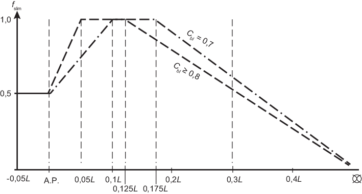
Figure 2.4.1 Longitudinal distribution of
slamming pressure at aft end
4.3 Bow impact loads
4.3.1
Application and limitations.
- The bow impact pressure applies to the side structure in the
area forward of 0,1L aft of F.P. and between the waterline at draught
 and the highest deck at side. and the highest deck at side.
4.3.2 Bow impact pressure.
- The bow impact pressure,
 , is to be taken as: , is to be taken as:
 kN/m2 kN/m2
where
 |
= |
0,55 at 0,1L aft of F.P. |
| = |
0,9 at 0,0125L aft of F.P. |
| = |
1,0 at, and forward of, F.P. |
intermediate values to be obtained by linear
interpolation
 = environmental factor due to dynamic wave pressure = environmental factor due to dynamic wave pressure
For the pressure calculation in between  and and  , the factor is be obtained by interpolating between
the , the factor is be obtained by interpolating between
the  factors for factors for  and for and for 
 = impact speed, in m/s = impact speed, in m/s
For fixed
locations, impact speed to be taken
as 5 sin
 = local waterline angle at the position considered,
but is not to be taken as less than 35°, see
Figure 2.4.3 Definition of bow
geometry = local waterline angle at the position considered,
but is not to be taken as less than 35°, see
Figure 2.4.3 Definition of bow
geometry
 = local bow impact angle measured normal to the shell
from the horizontal to the tangent line at the position considered, but
is not to be less than 50°, see
Figure 2.4.3 Definition of bow
geometry = local bow impact angle measured normal to the shell
from the horizontal to the tangent line at the position considered, but
is not to be less than 50°, see
Figure 2.4.3 Definition of bow
geometry
 = 1,0 for positions between draughts = 1,0 for positions between draughts  and and 
= 
for positions above draught 
 = vertical distance from the waterline at draught = vertical distance from the waterline at draught  to the highest deck at side, see
Figure 2.4.3 Definition of bow
geometry, in
metres to the highest deck at side, see
Figure 2.4.3 Definition of bow
geometry, in
metres
 = vertical distance from the waterline at draught = vertical distance from the waterline at draught  to the position considered, see
Figure 2.4.3 Definition of bow
geometry, in
metres to the position considered, see
Figure 2.4.3 Definition of bow
geometry, in
metres
L = Rule length, in metres
 = scantling draught, in metres = scantling draught, in metres
 = minimum design light draught, in metres = minimum design light draught, in metres
 = waterline at the position considered, see
Figure 2.4.3 Definition of bow
geometry = waterline at the position considered, see
Figure 2.4.3 Definition of bow
geometry

Figure 2.4.2 Longitudinal
distribution of slamming pressure at forward end

Figure 2.4.3 Definition of bow
geometry
|