
Section
1 General
1.1 Application
1.1.1 This Chapter outlines the hull structural design requirements of ship
units with hull construction in steel engaged in production and/or cargo
storage/offloading while permanently moored at offshore locations. For the purposes
of this Part, the term ‘cargo’ refers to crude oil, liquefied gas, condensate,
methanol, process chemicals including refrigerants and by-products of the production
process.
1.1.2 The Rules are also applicable to units which normally operate while
moored at offshore locations, but which are disconnectable in order to avoid extreme
environmental conditions or hazards, see also
Pt 4, Ch 3, 4 Structural design loads.
1.1.3 Units which operate as shuttle tankers will normally be assigned class
in accordance with the Rules and Regulations for the Classification of Ships
(hereinafter referred to as the Rules for Ships).
1.1.4 Hull strength, scantlings and arrangements for ship units are to comply
with Pt 10 Ship Units. Reference is also made to the
LR ShipRight Procedure for Ship Units.
1.1.5 All aspects which relate to the specialised offshore function of the
unit are to be considered on the basis of this Chapter and the additional
requirements related to the design arrangements and functions of drilling and
production units given in Pt 3, Ch 2 Drilling Units and Pt 3, Ch 3 Production and Storage Units are to be complied with.
1.1.6 The scantlings and arrangements of units with a limited number of tanks
for the storage of flammable liquids having a flash point not exceeding 60°C
(closed-cup test) will be specially considered.
1.1.7 The class notations and descriptive notes applicable to units classed in
accordance with these Rules are to be in accordance with List of abbreviations and Pt 3, Ch 3, 1 General, to which reference should be made.
1.1.10 Units with a process plant facility which comply with the requirements of
Pt 3, Ch 8 Process Plant Facility will be eligible for the assignment of the
special features class notation PPF.
1.1.11 Units with a drilling plant facility which comply with the requirements
of Pt 3, Ch 7 Drilling Plant Facility will be eligible for the assignment of the
special features class notation DRILL.
1.1.12 The structural design of integral tanks for the storage of condensates is
to comply with the requirements in this Part outlined for cargo tanks and other
tanks designed for liquid filling. The density of the condensate is not to be taken
as less than the minimum density values, as defined in Pt 10, Ch 2, 1.2 Definitions 1.2.3 in Pt 10, Ch 2 Loads and Load Combinations, for strength and fatigue assessments.
1.2 Definitions
1.2.2 Additional definitions relevant to Pt 10 Ship Units are given below:
 |
= |
deep load draught, in metres, is the maximum draught on
which the scantlings are based |
 |
= |
light load draught, in metres, is the minimum draught on
which the scantlings are based. |
|
L |
= |
Rule length, in metres, as defined in Pt 4, Ch 1, 5 Definitions |
|
FE |
= |
the fore end, FE, of the rule length L is the perpendicular
to the scantling draught waterline at the forward side of the stem,
see
Figure 1.1.1 Fore end, aft end and midship |
|
AE |
= |
the aft end, AE, of the rule length L is the
perpendicular to the scantling draught waterline at a distance L
aft of the fore end, see
Figure 1.1.1 Fore end, aft end and midship
|
|
Midship |
= |
the midship is the perpendicular to the scantling draught
waterline at a distance 0,5 L aft of fore end, see
Figure 1.1.1 Fore end, aft end and midship
|
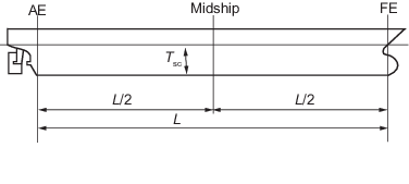
Figure 1.1.1 Fore end, aft end and midship
1.2.3
Moderate service. A Moderate service is one where the site-specific responses
of the vessel are less than or equal to the responses in unrestricted worldwide
transit. The following responses are to be compared:
- Hull girder vertical wave bending moment.
- Relative wave elevation.
- Vertical acceleration.
- Roll angle.
1.2.4 Harsh service. A Harsh service is one which does not satisfy the
definition of a Moderate service.
1.2.5
Transit. Any voyage of the unit, self-propelled or unpropelled, from one
geographical location to another. The following are considered transit conditions:
-
Delivery voyage. Delivery voyage of a unit along a defined route from
a shipyard or field to the operating site at which the OI class
notation is assigned. The delivery voyage is typically scheduled for
restricted sea states.
-
Restricted service area transit. Transit of a unit at any time across
a restricted service area. Voyages of this nature may be carried out by
disconnectable units that sail away within a defined service area either to
avoid approaching heavy weather and/or to return to a dry dock for
inspection.
-
Unrestricted worldwide transit. Transit of a unit at any time across
any sea area in the world. Voyages of this nature may be carried out by
disconnectable units that sail away either to avoid approaching heavy
weather and/or to return to a dry dock for inspection.
1.3 Application of transit conditions
1.3.1 All units are to be assessed for the delivery voyage. This is to ensure
that the unit arrives fit for entry into class at the operating field where the
OI class notation is assigned. The Owner is to define the wave
environment and the maximum transit speed for the delivery voyage.
1.3.2 Disconnectable units are to be assessed for unrestricted worldwide
transit, in which case the delivery voyage need not be assessed. The Owner is to
define the maximum transit speed for disconnected service. For unrestricted
worldwide transit, the loads defined in Pt 10, Ch 2, 7 Environmental loads for unrestricted worldwide transit condition are to be used. Alternatively, at the request of the Owner, the
unit may be assessed to transit within a restricted service area. In this case, a
service restriction will be placed on the unit and recorded in the class notation,
see
Pt 10, Ch 1, 1.2 Definitions 1.2.5.(b). The Owner is to define the wave environment for the restricted
service area.
1.4 Application of acceptance criteria
1.4.1 In general, the Working Stress Design (WSD) method is applied for the
assessment of the scantlings in Pt 10, Ch 3 Scantling Requirements. Three sets of acceptance criteria are given that are
dependent on the probability level of the characteristic combined loads.
1.4.2 The acceptance criteria set AC1 is applied when the combined
characteristic loads are frequently occurring, typically for the static design load
combination. This means that the loads occur on a frequent or regular basis. The
allowable stress for a frequent load is lower than for an extreme load and takes
into account allowance for some dynamics and operational mistakes.
1.4.3 The acceptance criteria set AC2 is typically applied when the combined
characteristic loads are extreme values, e.g. typically for the static + dynamic
design load combinations. High utilisation of the structural capacity is allowed in
such cases because the considered loads are extreme loads with a low probability of
occurrence.
1.4.4 The acceptance criteria set AC3 is typically applied for capacity
formulations based on plastic collapse models such as those that are applied to
address bottom and bilge slamming and bow impact loads.
|