
Section
3 Secondary member end connections
3.1 General
3.1.1 Secondary
members, that is longitudinals, beams, frames and bulkhead stiffeners
forming part of the hull structure, are generally to be connected
at their ends in accordance with the requirements of this Section.
3.1.2 Where
end connections are fitted in accordance with these requirements,
they may be taken into account in determining the effective span of
the member. For determination of span point,see
Pt 3, Ch 3, 3.3 Determination of span point.
3.2 Symbols
3.2.1 The symbols
used in this Section are defined as follows:
|
Z
|
= |
the
section modulus of the stiffening member, in cm3
|
3.3 Basis for calculation of bracket connections
3.3.1 Scantlings
of bracket connections are based on the following criteria:
-
Where a bracket
is connecting a stiffener to a primary member, the bracket is to be
based on the modulus of the stiffener;
-
Where a main transverse
frame terminates, the bracket at the head of the frame is to be based
on the modulus of the frame;
-
Where, in the midship
region, a longitudinal strength member is cut at a transverse supporting
member and the continuity of strength is provided by brackets, the
bracket is to be based on the cross-sectional area and the modulus
of the longitudinal member. Care is to be taken to ensure correct
alignment of the brackets on each side of the primary member;
-
Elsewhere, the lesser
modulus of the members being connected by the bracket.
3.4 Scantlings of end brackets
3.4.3 Where
the bracket is lapped on to the stiffening member, the length and
width of overlap is to be adequate to provide for the required area
of welding, but the length of overlap should be not less than the
depth of the stiffener.
3.4.4 For the
purpose of these Rules, bracket connections not complying with these
minimum requirements are considered as bracketless connections.
3.5 Arrangement and details
3.5.1 The modulus
of the bracket through the throat is to be not less than that of the
smaller stiffening member to be connected.
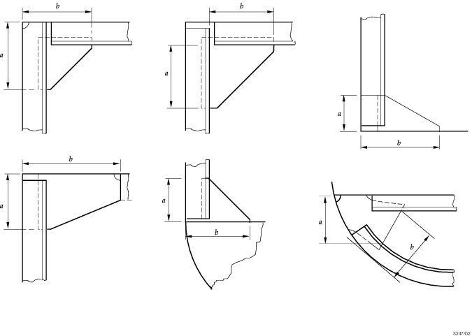
Figure 10.3.1 Diagrammatic arrangements of stiffener end brackets
Table 10.3.1 Bracket scantlings
| Parameter
|
Requirement
|
| Length of a bracket
|
The greater of the following:
|
l |
= |
 + 80 + d
s mm, or + 80 + d
s mm, or |
|
| Thickness
of a bracket
|
|
|
(a) unflanged
|
|
t
|
= |
5 +  mm mm |
see Note
|
|
(b) flanged
|
The greater of the following:
|
t
|
= |
4 +  mm, or mm, or |
|
| Flange width
|
|
t
|
= |
 mm mm |
|
| Symbols
|
|
b
f
|
= |
breadth of the flange, in mm |
|
d
s
|
= |
depth of the stiffening member, in mm |
|
l |
= |
arm length of bracket, in mm |
|
Note Where the length of the free edge of a bracket exceeds
50t mm, edge stiffening is to be fitted or the thickness is
to be suitably increased.
|
3.5.2 The design
of end connections and their supporting structure is to be such as
to provide adequate resistance to rotation and displacement of the
joint.
3.5.3 The toes
of brackets should not land on unstiffened panels of plating. Special
care should be taken to avoid notch effects at the toes of brackets.
3.6 Bracketless connections
3.6.1 For the
purpose of these Rules, bracketless connections are divided into two
types as follows:
3.6.2 Type 2 connections may only be adopted at watertight bulkhead stiffeners,
wash bulkhead stiffeners and at stiffeners on centreline division bulkheads (non-tight)
in tanks. Type 2 connections are not allowed for the secondary member end connections in
way of the deep tank boundary or the shell boundary.

Figure 10.3.2 Types of bracketless end connections
3.7 Correction of stiffening member modulus in relation to end connections
3.7.2 The modulus
of bracketless stiffeners is to be increased as follows:
| Type 1 connection:
|
increase 10 per cent per end
connection.
|
| Type 2 connection:
|
increase 25 per cent per end
connection.
|
3.8 End connections of corrugated bulkheads
3.8.1 The constraint
of the end connection is to be assured by the positioning of floors
and/or carlings or a corrugated bulkhead in line with the corrugated
bulkhead under consideration. This type of connection is considered
as a bracketless Type 1 connection, see also
Figure 10.3.3 End connections of corrugated bulkheads. Where the bulkhead corrugations
are not supported, the connection is considered as a Type 2 connection, see also
Figure 10.3.3 End connections of corrugated bulkheads.
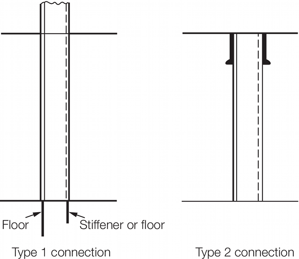
Figure 10.3.3 End connections of corrugated bulkheads
3.8.2 The yield stress of floors and/or carlings in line with the corrugated bulkhead is not
to be less than the yield stress of the corrugated bulkhead.
|
| Copyright 2022 Clasifications Register Group Limited, International Maritime Organization, International Labour Organization or Maritime
and Coastguard Agency. All rights reserved. Clasifications Register Group Limited, its affiliates and subsidiaries and their respective
officers, employees or agents are, individually and collectively, referred to in this clause as 'Clasifications Register'. Clasifications
Register assumes no responsibility and shall not be liable to any person for any loss, damage or expense caused by reliance
on the information or advice in this document or howsoever provided, unless that person has signed a contract with the relevant
Clasifications Register entity for the provision of this information or advice and in that case any responsibility or liability is
exclusively on the terms and conditions set out in that contract.
|
 |
|