
Section
1 Testing
1.1 General
1.1.1 Every lifting appliance is to be tested and thoroughly examined before
being taken into use for the first time or after any subsequent alteration or repair
which may affect the strength of the appliance, or at certain Periodical Surveys as
indicated in Ch 12, 3 Survey requirements.
1.1.2 Where testing machines (e.g. dynamometers) are used to apply test loads,
they are to be of a type approved by Lloyd’s Register (LR) as suitable for the intended
purpose. The machine is to be calibrated biennially by a recognised authority and the
accuracy is to be within ±2 per cent. Testing machines are not to be used for initial
testing; and although acceptable to LR for periodical re-testing or following repairs,
some National Authorities will not accept this form of testing.
1.1.3 Where test weights are used to apply test loads, the weights are to be
certified as accurate to within 2 per cent.
1.1.4 Water bags may be used instead of certified weights for testing lifting
appliances. Where used, these are to be of a type suitable and certified for the
purpose. The volume of water is to be measured using a calibrated flow meter which has
been certified as accurate to within ±2 per cent. As an alternative, use of calibrated
load cells certified as accurate to within ±2 per cent for determining the test loads
could also be accepted. The flow meters and load cells are to be re-certified
biennially.
1.1.5 Suitable precautions are to be taken before commencing the test to ensure
the stability of the ship throughout the load test and also in case of a failure of the
load test. The adequacy of the supporting structure to bear the test loads is also to be
ensured.
1.1.6 A risk assessment is to be carried out to evaluate the consequences of any
failures during the load test and the identified risks are to be mitigated to acceptable
levels. The system integrator in cooperation with the manufacturer of the crane and the
designer of vessel shall prepare a Safety Statement in line with LR’s ShipRight
Procedure Risk Based Certification (RBC) process and/or in line with the
requirements of the National Administration (as applicable).
The risk mitigation may include the following measures;
- the application of a testing concept that would identify components along the main
load path which could be tested separately before assembly of the lifting appliance
on board, where the extent of the separate testing is also to be based on the results
of the risk assessment;
- positioning of the test load (e.g. at the stern of the ship) in such a way that any
single point failure (e.g. drop of load) will not lead to further failures (e.g.
collapse of parts of the crane); and
- consideration of the design of the ship and lifting appliance as a single system in
such a way that any single point failure will not lead to further failures (e.g.
capsizing of the ship, damage of the crane, possible interference with any onboard
structure).
1.1.7 Measures are to be taken to ensure that the appliance can be controlled
during the test and to avoid injury or damage which might occur in the event of failure
under load.
1.1.8 Lifting appliances are generally to hold the test weights for at least 5
minutes, but this may be extended at the discretion of the Surveyor.
1.2 Loose gear
1.2.1 For the purpose
of these requirements, loose gear is defined as including hooks, hook
blocks, shackles, blocks, swivels, chains, rings and similar items
not permanently attached to the lifting appliance. Lifting beams,
spreaders, frames, grabs and similar items of equipment which are
not an integral part of the lifting appliance are also considered
as loose gear. Built-in sheaves and blocks and other items permanently
attached to the lifting appliance are not considered as loose gear
and the test on the complete system ‘as rigged’ will be
accepted as the test on these items.
1.2.2 Every item of loose gear is to be proof load tested and thoroughly examined
before being taken into use for the first time and prior to fitting to a lifting
appliance or after any subsequent repair or alteration which may affect the strength of
the item. The proof load applied to each item of loose gear is to be as required by
Table 12.1.1 Proof loads for loose gear and associated Notes, and
illustrated in Figure 12.1.1 Proof loads for loose gear.
1.2.3 For all blocks
(single and multi-sheave), the proof load is to be taken as the resultant
load and applied to the head fitting of the block during the test.
Where the block is fitted with a becket, the load applied to the becket
during the load test of the block will be accepted as the proof test
on the becket.
1.2.4 Sheave blocks
that are permanently attached to, or integral with, the hook are called
cargo hook blocks and are to be tested with a proof load for multi-sheave
blocks as indicated in Table 12.1.1 Proof loads for loose gear.
The hooks are to be tested with a proof load for hooks as indicated
in Table 12.1.1 Proof loads for loose gear.
Table 12.1.1 Proof loads for loose gear
| Item
|
Proof load, in tonnes
|
| Single
sheave block
|
4 x SWL
|
|
|
|
| Multi-sheave blocks:
|
|
|
|
SWL ≤ 25 t
|
2 x SWL
|
|
|
25 t < SWL ≤ 160 t
|
(0,933 x SWL) + 27
|
|
|
160 t < SWL
|
1,1 x SWL
|
|
|
|
| Hooks,
shackles, chains, rings, swivels, etc.:
|
|
|
|
SWL ≤ 25 t
|
2 x SWL
|
|
|
25 t < SWL
|
(1,22 x SWL) + 20
|
|
|
|
| Lifting
beams, spreaders, frames, grabs:
|
|
|
|
SWL ≤ 10 t
|
2 x SWL
|
|
|
10 t < SWL ≤ 160 t
|
(1,04 x SWL) + 9,6
|
|
|
160 t < SWL
|
1,1 x SWL
|
Note
1. The safe working load for a single
sheave block, including single sheave blocks with beckets, is to be
taken as one half of the resultant load on the head fitting.
Note
2. The safe working load for a
multi-sheave block is to be taken as the resultant load on the head
fitting.
Note
3. Where the item is to be used in diving
operations, the proof load is to be 1,5 times the proof load value
given above for the particular item.
Note
4. Where the item is to be used for
offshore use, the proof loads indicated are to be increased by the
ratio F
h/1,6 where F
h is derived from Ch 4, 3.3 Dynamic forces.
Note
5. Single sheave blocks that have a
resultant load greater than 25 t can have a reduced test load
calculated on the basis of a multi-sheave block [(0,933 x RL) + 27
t].
Note 7. Items not covered above will be specifically
considered.
|
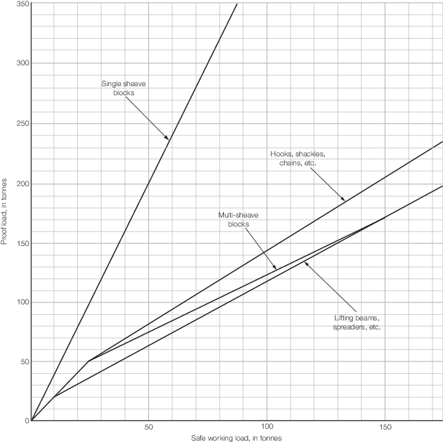
Figure 12.1.1 Proof loads for loose gear
1.2.5 After proof
testing, all parts of the blocks are to be thoroughly examined for
deformations, cracks, flaws, or other defects and to check that head
fittings can swivel and sheaves rotate freely.
1.2.7 Short and
long link chain is to be subjected to a breaking test in addition
to the proof test required by Table 12.1.1 Proof loads for loose gear.
One sample of length 910 mm is to be taken from each length of chain
measuring 185 m or less and is to withstand a breaking load of 4 x
SWL for the chain.
1.2.8 Where the
design of a lifting beam, frame, or similar item is such that the
load can be lifted and supported in more than one manner, each arrangement
is to be separately tested. Alternative testing proposals outlining
how all components will be loaded above their maximum design load
(but not above the required test load) will be specially considered
subject to the Surveyor’s satisfaction. Hooks, shackles and
blocks forming part of the lifting beam or frame are to be separately
tested in accordance with Table 12.1.1 Proof loads for loose gear.
1.2.9 Where the
loose gear is for use in an offshore, open sea or diving application,
the selection of the component of loose gear should take account of
the higher proof loads required by Notes 3 and 4 of Table 12.1.1 Proof loads for loose gear.
1.3 Steel wire rope
1.3.1 Steel wire
used in the construction of ropes is to be subjected to breaking,
torsion and reverse bend tests and to tests for quality and adhesion
of the zinc coating in accordance with ISO 2232 Round Drawn
Wire for General Purpose Nonalloy Steel Wire Ropes – Specifications or with an acceptable equivalent. Where required, similar
tests may be carried out on wires taken from samples of completed
ropes.
1.3.2 Steel wire
ropes are to be tested to determine the breaking load of the rope.
Tests in accordance with International or recognised National Standards
may be accepted and, in this respect, attention is drawn to the following
International Standards:
- ISO 2408 Steel wire ropes for general purposes – Minimum
requirements.
- ISO 3108 Steel wire rope for general purposes – Determination
of actual breaking load.
1.3.3 The breaking
load is to be determined by one of the following methods:
-
Testing to destruction
a sample cut from the completed rope.
-
Testing the individual
wires to destruction, summating the results and deducting a percentage
for laying up.
This percentage is to be not less than as given in Table 12.1.2 Percentage deduction for laying
up. Manufacturers adopting
this method of testing will be required to arrange for occasional
tensile tests to destruction to be carried out on completed ropes.
Table 12.1.2 Percentage deduction for laying
up
| Rope construction
|
Percentage deduction
|
| Fibre core
|
Steel core
|
| WSC
|
IWRC
|
| 6 x 710
|
12
|
17
|
—
|
| 6 x
19
|
14
|
16
|
21
|
| 6 x
37
|
17,5
|
20
|
25
|
| 6 x 19
Seale
|
16
|
—
|
23
|
| 6 x 19
Filler
|
16
|
—
|
23
|
| 6 x 26
Warrington-Seale
|
16
|
—
|
23
|
| 6 x 31
Warrington-Seale
|
16
|
—
|
23
|
| 6 x 36
Warrington-Seale
|
16
|
—
|
23
|
| 6 x 41
Warrington-Seale
|
16
|
—
|
23
|
| 6 x 12
|
10
|
—
|
—
|
| 6 x 24
|
13
|
—
|
—
|
| 17 x 7 and
18 x 7
|
22
|
22
|
—
|
| 34 x 7 and 36 x 7
|
25
|
25
|
—
|
Note
- WSC = wire strand core
- IWRC = independent wire rope core.
|
1.3.4 Before a
test sample is cut from the rope, it is to be securely seized or clamped
so as to prevent any slacking of wires within the test length. The
sample is to be of sufficient length to provide a clear test length
in accordance with Table 12.1.3 Test length for steel wire
ropes.
Table 12.1.3 Test length for steel wire
ropes
| Wire rope diameter, d, in mm
|
Test length, in
mm
|
|
d ≤ 6
|
300
|
| 6 < d ≤ 20
|
600
|
|
d > 20
|
30d but need not exceed 1500 mm
|
1.3.5 Up to 80
per cent of the nominal breaking load may be applied quickly. Thereafter,
the load is to be applied slowly and steadily until the maximum load
is attained. Tests in which a breakage occurs adjacent to the grips
may be neglected.
1.3.6 Terminal connections, where used, are to be of a type acceptable to LR and
manufactured to a recognised National or International Standard. Proprietary terminal
connects not manufactured to a recognised National or International Standard will be
specially considered.
Initial tests are to be carried out on various sizes of connections to show
that the strength of the completed termination is not less than the following percentage
of minimum breaking load of the original wire rope:
- For metal and resin sockets, ferrules and ferrule-securing and swage sockets:
- 95 per cent for ropes up to 50 mm diameter; or
- 90 per cent for ropes exceeding 50 mm diameter.
- For wedge sockets:
After completion, each terminal connection is to be proof tested to twice
the SWL on the rope. However, for larger terminations where the safety factor on the
rope is between 3,0 and 4,0, testing of the termination is not to exceed 50 per cent of
the minimum breaking load strength of the rope.
1.3.7 Poured zinc
and resin sockets do not require proof testing, provided:
-
The termination has
been carried out by a competent person in accordance with a recognised
procedure and material requirement.
-
The sockets are in
accordance with a recognised Standard and are certified.
1.4 Fibre rope
1.4.1 Fibre ropes
are to be tested to determine the breaking load of the rope. Additional
tests may be required, particularly in the case of ropes manufactured
from man-made materials, in order to establish the suitability of
the rope for its intended purpose.
1.4.2 Manufacture
and testing are to be in accordance with international or recognised
National Standards where appropriate.
1.4.3 The breaking
load is to be determined by testing to destruction a sample cut from
the completed rope. Alternative proposals will, however, be specially
considered where a breaking test would be impracticable.
1.4.4 The minimum
length of test sample is to be as given in Table 12.1.4 Testing of fibre ropes. The sample is to be subjected to an initial tensile
load as given in Table 12.1.4 and checked for diameter and evenness
of lay-up. The load is then to be increased evenly and continuously
by stretching the sample at the rate given in Table 12.1.4 Testing of fibre ropes until the sample breaks. Tests in which a breakage
occurs within 150 mm of the grips may be neglected.
Table 12.1.4 Testing of fibre ropes
| Material
|
Test
length, in mm
|
Initial load,
see Note
|
Speed
of loading in mm/min
|
| Natural fibre
|
1800
|
2
|
250 ± 50
|
| Synthetic
fibre
|
900
|
1
|
75 ±
25
|
Note Initial load is expressed as a percentage of the nominal
breaking load of the rope.
|
1.5 Derricks and derrick cranes
1.5.1 Following
any preliminary part load tests considered necessary to ensure correct
assembly and freedom of operation, each derrick in the system is to
be tested with a test load in accordance with Table 12.1.5 Testing of derricks and
cranes. The test is to be carried out using certified
weights suspended from the cargo hook or lifting attachment, according
to a procedure agreed with the Surveyor.
Table 12.1.5 Testing of derricks and
cranes
| SWL of derrick, crane
or ROV handling system, in tonnes
|
Test
load, in tonnes
|
| Up to
20 t
|
1,25 x
SWL
|
| 20 t < SWL ≤ 50
t
|
SWL +
5 t
|
| 50 t
< SWL
|
1,1 x
SWL
|
Note Hand operated pulley blocks are to be proof tested to 1,5
x SWL.
|
1.5.2 During the
test, hoisting and slewing operations are to be carried out at slow
speed. The load is to be slewed as far as possible in both directions
with the derrick boom at the lowest angle to the horizontal for which
it has been approved, see
Ch 2 Derrick Systems.
1.5.3 In addition
to verifying the adequacy of the derrick and the support structure,
the test is to demonstrate the adequacy of the winch brakes, controls
and any overload cutout, safe load indicators, etc. The test is also
to demonstrate that the test load can be held stationary when the
winch drive is switched off, see also
Ch 9 Machinery.
1.5.4 Where derricks
have been approved for operation in union purchase, they are to be
rigged and tested for working both port and starboard sides of the
ship. The test is to be carried out for the headroom, runner angle
and boom and guy positions for which the rig has been approved, with
a test load in accordance with Table 12.1.5 Testing of derricks and
cranes for
the SWL of the system in union purchase operation.
1.5.5 Following
the overload test, the derrick is to be operationally tested with
its safe working load. The derrick is to be operated over its full
range of positions at normal speeds and it is to be demonstrated that
all parts of the system are free to take up their correct positions
and that all ropes run freely and reel up correctly on the winch drums.
1.5.6 After testing,
the derrick system is to be thoroughly examined for deformations and
other defects.
1.5.7 Derrick cranes
are to be tested in accordance with Ch 12, 1.5 Derricks and derrick cranes 1.5.1, with the addition that the derrick crane is to be
luffed at slow speed to its maximum operating angle to the horizontal
while bearing the full test load.
1.5.8 Where twin
span tackles are fitted to derrick cranes of patent type, the manufacturer
may be required to demonstrate during testing with the SWL that the
derrick boom has adequate stability when in the maximum slewed position
for both maximum and minimum luffing angles under the maximum approved
angles of heel and trim of the ship.
1.6 Cranes and ROV handling systems
1.6.1 Following
any preliminary part load tests considered necessary to ensure correct
assembly and freedom of operation, each crane or ROV handling system
is to be tested with a test load in accordance with Table 12.1.5 Testing of derricks and
cranes. The test is to be carried
out using certified weights suspended from the cargo hook or lifting
attachment, according to a procedure agreed with the Surveyor.
1.6.2 During the
test the crane is to hoist, slew and luff the test load at slow speed.
Gantry and travelling cranes together with their travelling trolleys,
where appropriate, are to be traversed slowly over the full length
of their track. ROV handling systems are to lift the test load through
one complete operating cycle.
1.6.3 In the case
of a variable load-radius crane, the tests are, generally, to be carried
out for the appropriate safe working loads at maximum, minimum and
an intermediate radius. Alternative proposals will, however, be considered.
1.6.4 Where the
jib length may be increased by the insertion of additional lengths,
the crane is to be tested for each jib length. Alternative testing
proposals outlining how all components will be loaded above their
maximum design load (but not above the required test load) will be
specially considered subject to the Surveyor’s satisfaction.
1.6.5 Where it
is not practicable for the crane to raise the full test load, as may
be the case for hydraulic cranes, a reduced test load may be accepted,
but in no case is this to be less than 1,1 x SWL. Although acceptable
to LR, this test at reduced load may not be acceptable to some National
Authorities.
1.6.6 Following
the overload test, the crane is to be loaded with its safe working
load and operated over its full range of speeds in order to demonstrate
the effective operation of the crane, the accuracy of overload and
safe load indicators and the effectiveness of limit switches, etc.
1.6.7 Following
the overload test, the ROV handling system is to be operated with
its SWL over its complete operating cycle to demonstrate the effective
operation of the handling system, the accuracy of overload and safe
load indicators and the effectiveness of limit switches, etc.
1.6.10 After testing,
the crane or ROV handling system is to be thoroughly examined for
deformations and other defects.
1.7 Manned submersible handling systems
1.7.1 For the purpose of these requirements, the term ‘manned submersible handling systems’
includes the handling of manned diving systems.
1.7.2 Upon completion of preliminary tests necessary to ensure correct assembly and freedom of
operation, each lifting appliance used for raising, lowering or transferring manned
submersibles is to be subjected to the following tests:
-
A ‘static’ load test equivalent to 1,5 SWL. In the case of cranes or A
frames, this load is to be lifted at the maximum and minimum radii or
inboard/outboard positions and at an intermediate position.
-
A ‘dynamic’ load test equivalent to 1,1 SWL. This test is to
demonstrate that the hoist brake system is capable of stopping the load whilst
being lowered at maximum speed to simulate a power failure.
-
An ‘operational’ load test equivalent to 1,25 SWL. This test is to be
carried out over the full range of operation of the lifting appliance.
1.7.5 For the purpose
of these requirements, the safe working load of the appliance is to
be taken as the greater of:
-
The maximum in-air weight of the manned submersible, lifting frame
and rope when it is at water surface; or
-
The total submerged weight of the manned submersible, lifting frame
and rope when it is at its maximum operating depth.
1.7.6 Following the overload test, the manned submersible handling system is to be
operated with its SWL over the complete operating cycle to demonstrate the effective
operation of the system, the accuracy of overload and safe load indicators and the
effectiveness of limit switches, etc.
1.7.7 After testing, the manned submersible handling system is to be thoroughly
examined for deformations and other defects.
1.7.8 Further tests in accordance with LR’s Rules and Regulations for the
Construction and Classification of Submersibles and Diving Systems may be
required and reference is made to that publication. Where compliance with National
Authority Regulations is required, specific reference should be made to the Regulations
in case any additional or more onerous test requirements are appropriate.
1.8 Launch and recovery appliances for manned small watercraft
1.8.4 Each of the primary and secondary brakes shall be statically tested to at least 1,5
times SWL and dynamically tested to at least 1,1 times SWL.
1.9 Mechanical lift docks
1.10 Lifts and ramps
1.10.1 Attention
is drawn to the existence of statutory requirements of certain National
Authorities for the testing of lifts, particularly of passenger lifts.
1.10.2 Each lift
is to be tested with its applied or rated load, see
Ch 6 Ro-Ro Access Equipment and Ch 7 Lifts,
to demonstrate the satisfactory operation of the lift and all control
and safety systems.
1.10.3 In addition, after installation or following any major repair, renewal or
alteration, each lift is to be subjected to the following tests:
-
For all lifts, the
brake is to hold the lift with a proof load of 1,25 times the applied
or rated load.
-
The lift is to be operated
through one complete round trip with a proof load of:
-
Passenger lifts:
1,1 times the applied or rated load.
-
Cargo or vehicle
lifts: in accordance with Table 12.1.6 Test load for cargo or vehicle
lifts.
Table 12.1.6 Test load for cargo or vehicle
lifts
| SWL, in tonnes
|
Test load, in
tonnes
|
| Up to 20 t
|
1,25 x SWL
|
| 20 t < SWL ≤ 50 t
|
SWL + 5 t
|
| 50 t < SWL
|
1,1 x SWL
|
1.10.4 Vehicle ramps
which may be raised or lowered while loaded are to be tested as for
vehicle lifts.
1.10.5 Vehicle ramps
which are raised or lowered only when unloaded are to be tested after
installation and following any major repair, renewal or alteration
as follows:
-
The brake is to hold
the ramp in its most unfavourable position while the ramp is subjected
to a load of 1,25 times its self-weight.
-
The ramp is to be placed
in its working position and subjected to a test load as given for
vehicle lifts in Ch 12, 1.10 Lifts and ramps 1.10.3.(b).
-
The ramp is to be operated
through one complete operating cycle, unloaded, using the terminal
stops only.
1.11 Re-testing
1.11.1 Re-testing
of loose gear is to be carried out in the following circumstances:
-
In the absence of
an appropriate certificate indicating that the item has previously
been tested;
-
Following any repair
or alteration which may affect the strength of the item;
-
If the item’s
unique identification mark has become illegible;
-
As required by the
National Administration.
1.11.3 Re-testing
of derrick systems, derrick cranes, cranes, and ROV handling systems
is to be carried out in the following circumstances:
-
Following any structural
repair, alteration or re-erection of the appliances;
-
At every fifth Annual
Thorough Survey, or in accordance with the requirements of the National
Administration.
1.11.4 These tests
need not be as extensive as the initial tests, but it must be demonstrated
that the test load can be raised and lowered. It is preferable also
for the derrick or crane to be slewed and luffed during the re-test,
but this may be waived at the discretion of the Surveyor.
1.11.5 Re-testing
of union purchase rigs is not essential, provided the derrick has
been re-tested in single working and special attention is paid to
the condition of the preventer guy eyeplate attachment to the deck.
1.11.6 Derricks
and cranes having a safe working load not exceeding 15 t may be re-tested
using a spring or hydraulic weighing machine, provided:
-
The machine has an
accuracy within ±2,0 per cent and the load is applied for at
least five minutes with the indicator remaining constant;
-
The derrick boom is
placed in the most onerous certified operating position;
-
The support point
for the machine is adequately strengthened to avoid overstressing
of the supporting structure; and
-
This method of test
is acceptable to the appropriate National and Port Authorities.
1.11.7 Lifting
appliances used for raising, lowering or transferring manned submersibles
or other diving systems are to be re-tested annually in accordance
with Ch 12, 1.7 Manned submersible handling systems. Re-testing will also be
required following any structural repairs, alterations or re-erection
of the appliance.
1.11.8 Lifts
and ramps are to be re-tested at every fifth Annual Thorough Survey,
depending on the requirements of the National Administration, and
also when repairs or alterations have been carried out affecting the
strength of the item. The re-test is to be in accordance with Ch 12, 1.10 Lifts and ramps 1.10.3.
|