
Section
2 Design criteria
2.1 Operating range for derricks
2.1.1 Calculations
are to be made for derrick systems with the derrick booms at the maximum
and minimum angles for which the system is to be certified. These
angles are to be taken as follows:
-
Maximum angle to the
horizontal:
70° generally, but a greater angle may be specified.
-
Minimum angle to the
horizontal:
-
SWL not exceeding
15 t:
30° generally, but a lesser angle may be specified.
In no case is the angle to be less than 15°.
-
SWL exceeding 15
t:
30° generally, but a greater angle may be specified.
In no case is the angle to be greater than 45°.
2.1.2 The length
of the derrick boom is to be such as to give adequate coverage of
the cargo hatch and sufficient outreach beyond the ship’s side,
within the limiting angles given in Ch 2, 2.1 Operating range for derricks 2.1.1.
2.2 Inclination of the ship
2.2.1 For swinging
derrick and union purchase systems, a basic angle of heel of 5°
and a trim of 2° are assumed for the ship. Provided these angles
are not exceeded, they may generally be ignored in the calculation
of forces and tensions in the derrick system and in the masts and
derrick posts.
2.2.2 The angles
of heel and trim of the ship with its largest loaded derrick (or derricks
if more than one can be used at one time) swung fully outboard are
to be calculated. Where the calculation shows that the ship would
have a greater angle of heel or trim than 5° or 2° respectively,
the actual angles are to be taken into consideration. This calculation
is NOT to be taken to mean that LR accepts responsibility for the
stability of the ship. Stability is a matter to be agreed between
the Builder, designer and Owner and may be subject to National Regulations.
2.2.3 For derrick
cranes, a basic angle of heel of 5° and a trim of 2° is generally
to be included in the calculations. Greater or lesser angles may be
specified provided these angles are clearly stated in the certificates.
2.3 Weight of boom and tackle
2.3.1 The weight
of the derrick boom and tackle is to be included in the calculations
for all union purchase rigs and for swinging derricks and derrick
cranes where the SWL exceeds 15t. Where available, the
actual weight of the derrick boom and tackle is to be used. Alternatively,
an estimated value equal to 10 per cent of the SWL of the system when
rigged as a swinging derrick or derrick crane is to be applied at
the derrick boom head.
2.4 Friction allowance
2.4.1 For calculation
purposes, a combined allowance for sheave friction and wire stiffness
is to be made as follows:
| •
|
Blocks with plain or bushed
sheaves:
|
|
5 per cent
|
| •
|
Blocks with ball or roller
sheaves:
|
|
2 per cent
|
| Allowances for sheaves with low friction bearings will
be specially considered.
|
2.4.2 The appropriate
percentage is to be applied cumulatively to the parts of the rope
supporting the load. Coefficients for estimating the rope tension
are given in Table 2.2.1 Coefficients of rope
tension and in
association with Figure 2.2.1 Coefficients of rope
tension.
Table 2.2.1 Coefficients of rope
tension
Number
of
parts
supporting
the load
|
Friction
allowance
per
sheave %
|
Static
rope pull
|
Hoisting
|
Lowering
|
|
P
0
|
P
1
|
P
2
|
P
3
|
P
4
|
P
5
|
P
0
|
P
1
|
P
2
|
P
3
|
P
4
|
P
5
|
|
F
0
|
F
1
|
F
2
|
F
3
|
F
4
|
F
5
|
F
0
|
F
1
|
F
2
|
F
3
|
F
4
|
F
5
|
| 1
|
2
|
1,00
|
—
|
—
|
1,02
|
1,04
|
1,06
|
1,08
|
—
|
—
|
0,98
|
0,96
|
0,94
|
0,92
|
|
|
5
|
—
|
—
|
1,05
|
1,10
|
1,16
|
1,22
|
—
|
—
|
0,95
|
0,91
|
0,86
|
0,82
|
|
|
|
|
|
|
|
|
|
|
|
|
|
|
|
|
| 2
|
2
|
0,500
|
0,495
|
0,505
|
0,515
|
0,525
|
0,536
|
0,547
|
0,505
|
0,495
|
0,485
|
0,476
|
0,467
|
0,457
|
|
|
5
|
0,488
|
0,512
|
0,538
|
0,565
|
0,593
|
0,623
|
0,512
|
0,488
|
0,465
|
0,443
|
0,421
|
0,401
|
|
|
|
|
|
|
|
|
|
|
|
|
|
|
|
|
| 3
|
2
|
0,333
|
0,327
|
0,340
|
0,347
|
0,354
|
0,361
|
0,368
|
0,340
|
0,327
|
0,320
|
0,314
|
0,308
|
0,302
|
|
|
5
|
0,317
|
0,350
|
0,357
|
0,386
|
0,405
|
0,425
|
0,350
|
0,317
|
0,302
|
0,288
|
0,274
|
0,261
|
|
|
|
|
|
|
|
|
|
|
|
|
|
|
|
|
| 4
|
2
|
0,250
|
0,243
|
0,258
|
0,263
|
0,268
|
0,273
|
0,279
|
0,258
|
0,243
|
0,238
|
0,233
|
0,229
|
0,224
|
|
|
5
|
0,232
|
0,269
|
0,282
|
0,296
|
0,311
|
0,327
|
0,259
|
0,232
|
0,221
|
0,210
|
0,200
|
0,191
|
|
|
|
|
|
|
|
|
|
|
|
|
|
|
|
|
| 5
|
2
|
0,200
|
0,192
|
0,208
|
0,212
|
0,216
|
0,221
|
0,225
|
0,208
|
0,192
|
0,188
|
0,185
|
0,181
|
0,178
|
|
|
5
|
0,181
|
0,220
|
0,231
|
0,243
|
0,255
|
0,267
|
0,220
|
0,181
|
0,172
|
0,164
|
0,156
|
0,149
|
|
|
|
|
|
|
|
|
|
|
|
|
|
|
|
|
| 6
|
2
|
0,167
|
0,159
|
0,175
|
0,179
|
0,182
|
0,186
|
0,189
|
0,175
|
0,159
|
0,155
|
0,152
|
0,149
|
0,146
|
|
|
5
|
0,147
|
0,188
|
0,197
|
0,207
|
0,217
|
0,228
|
0,188
|
0,147
|
0,140
|
0,133
|
0,127
|
0,121
|
|
|
|
|
|
|
|
|
|
|
|
|
|
|
|
|
| 7
|
2
|
0,143
|
0,135
|
0,152
|
0,155
|
0,158
|
0,160
|
0,164
|
0,152
|
0,135
|
0,132
|
0,129
|
0,127
|
0,124
|
|
|
5
|
0,123
|
0,165
|
0,173
|
0,181
|
0,191
|
0,200
|
0,155
|
0,123
|
0,117
|
0,111
|
0,106
|
0,101
|
|
|
|
|
|
|
|
|
|
|
|
|
|
|
|
|
| 8
|
2
|
0,125
|
0,117
|
0,134
|
0,137
|
0,139
|
0,142
|
0,145
|
0,134
|
0,117
|
0,114
|
0,112
|
0,110
|
0,108
|
|
|
5
|
0,105
|
0,147
|
0,155
|
0,162
|
0,171
|
0,179
|
0,147
|
0,105
|
0,100
|
0,095
|
0,090
|
0,086
|
|
|
|
|
|
|
|
|
|
|
|
|
|
|
|
|
| 9
|
2
|
0,111
|
0,103
|
0,120
|
0,123
|
0,125
|
0,128
|
0,130
|
0,120
|
0,103
|
0,101
|
0,099
|
0,097
|
0,095
|
|
|
5
|
0,091
|
0,134
|
0,141
|
0,148
|
0,155
|
0,163
|
0,134
|
0,091
|
0,086
|
0,082
|
0,078
|
0,075
|
|
|
|
|
|
|
|
|
|
|
|
|
|
|
|
|
| 10
|
2
|
0,100
|
0,091
|
0,109
|
0,111
|
0,114
|
0,116
|
0,118
|
0,109
|
0,091
|
0,090
|
0,088
|
0,086
|
0,084
|
|
|
5
|
0,080
|
0,123
|
0,130
|
0,136
|
0,143
|
0,150
|
0,123
|
0,080
|
0,076
|
0,072
|
0,069
|
0,065
|
|
|
|
|
|
|
|
|
|
|
|
|
|
|
|
|
| 11
|
2
|
0,091
|
0,082
|
0,100
|
0,102
|
0,104
|
0,106
|
0,108
|
0,100
|
0,082
|
0,081
|
0,079
|
0,077
|
0,076
|
|
|
5
|
0,070
|
0,115
|
0,120
|
0,126
|
0,133
|
0,139
|
0,115
|
0,070
|
0,067
|
0,064
|
0,061
|
0,058
|
|
|
|
|
|
|
|
|
|
|
|
|
|
|
|
|
| 12
|
2
|
0,083
|
0,075
|
0,093
|
0,095
|
0,097
|
0,099
|
0,100
|
0,093
|
0,076
|
0,073
|
0,072
|
0,070
|
0,069
|
|
|
5
|
0,063
|
0,108
|
0,113
|
0,118
|
0,124
|
0,131
|
0,108
|
0,063
|
0,060
|
0,057
|
0,054
|
0,052
|
|
|
|
|
|
|
|
|
|
|
|
|
|
|
|
|
| 13
|
2
|
0,077
|
0,068
|
0,086
|
0,088
|
0,090
|
0,092
|
0,094
|
0,086
|
0,068
|
0,067
|
0,066
|
0,064
|
0,063
|
|
|
5
|
0,057
|
0,101
|
0,107
|
0,112
|
0,117
|
0,123
|
0,101
|
0,057
|
0,054
|
0,051
|
0,049
|
0,046
|
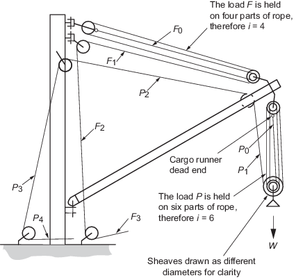
Figure 2.2.1 Coefficients of rope
tension
2.4.3 As an alternative, the coefficients of rope tensions may be determined as
follows:
where
|
μ |
= |
percentage of friction (e.g. 2 per cent for roller bearings) |

|
= |
number of parts supporting the load |
2.5 Factor of safety for ropes
2.5.1 Wire ropes
are to have a breaking load not less than the maximum tension in the
rope multiplied by a factor obtained from Table 2.2.2 Factors for wire ropes.
Table 2.2.2 Factors for wire ropes
| Item
|
Factor
|
| (1)
|
Running rigging:
Cargo
runner
Span tackle
Slewing
guys
Preventer guys
Schooner guys
|
but not greater than 5 or less than 3
|
| (2)
|
Standing rigging:
Mast
stays
|
As for running rigging but need not
exceed 3,5
|
|
Note SWL is the safe working
load of the derrick or derrick crane with which the rope is to be used.
For standing rigging, SWL is the highest safe working load of any derrick
or derrick crane supported by the mast.
|
2.5.2 Natural fibre
ropes used in derrick systems, where permitted, are to have a breaking
load not less than the maximum tension in the rope multiplied by 8.
2.5.3 Man-made fibre
ropes, where permitted for standing rigging, are to have a breaking
load not less than the value obtained from Table 2.2.2 Factors for wire ropes multiplied by 1,25.
|