
Section
4 Union purchase arrangements
4.1 General
4.1.1 Where the
derricks are arranged for operation in union purchase, the maximum
resultant loads in the system are to be determined, in accordance
with the requirements of this Section.
4.1.2 The scantlings
and arrangements of the derrick system are to be determined for union
purchase operation and for operation as single slewing derricks. Each
part of the rig is to be suitable for the most severe loading to which
it may be subjected.
4.1.3 The union
purchase rig is generally to be designed so that the operation is
possible on either side of the ship. A typical rig is shown in Figure 2.4.1 Typical union purchase rig.

Figure 2.4.1 Typical union purchase rig
4.1.4 Union purchase
rigs may be designed on the basis of either:
-
minimum headroom below
the triangle plate; or
-
maximum included angle
between the cargo runners.
4.1.5 The following
criteria are to be complied with at all times:
-
Minimum operating angle
of either derrick is to be not less than 15° to the horizontal,
and it is recommended this angle is not less than 30°.
-
Minimum headroom to
the triangle plate is to be not less than 4,0 m where the SWL(U) of
the rig does not exceed 2,0 t, or 5,0 m for higher values of SWL(U).
-
The maximum included
angle between the cargo runners is not to exceed 120°.
-
The outreach beyond
the midship breadth of the ship is to be not less than 4,0 m.
4.1.6 The minimum
headroom is defined as the least vertical in distance at any stage
in the operating cycle of the rig, from the highest point of the ship’s
deck structure (usually the top of the hatch coaming or the ship side
bulwark or rails) to the centre of the triangle plate.
4.2 Working range of the rig
4.2.1 The derrick
booms are to be of sufficient length and to be so positioned as to
cover the required working area of the hatch while complying with
the criteria given in Ch 2, 4.1 General 4.1.5.
4.2.2 For this purpose,
the booms are to be such that the boom heads may be located at the
positions listed in Table 2.4.1 Boom head positions for union
purchase calculations.
These arrangements are illustrated in Figure 2.4.2 Positions of derricks for union
purchase and Figure 2.4.2 Positions of derricks for union
purchase for hatches
with one pair and two pairs of derricks respectively.
Table 2.4.1 Boom head positions for union
purchase calculations
| Boom and direction
|
Symbol
|
Number of pairs of booms at the hatch
|
| One
|
Two
|
| Dimension, in metres
|
| Outboard
boom
|
|
|
|
|
|
Transverse
|
y
o
|
4
|
4
|
|
|
Longitudinal
|
x
o
|
0,25lh
|
0,20lh
|
|
|
|
|
|
|
| Inboard
boom:
|
|
|
|
|
|
Case
1
|
Transverse
|
y
j
|
1
|
1
|
|
|
|
Longitudinal
|
xj
|
0,75lh
|
0,67lh
|
|
|
Case
2
|
Transverse
|
y
j
|
0,25b
h
|
0,25b
h
|
|
|
|
Longitudinal
|
x
j
|
0,375lh
|
0,33lh
|
Note
2. Case 2 is applicable to operation in
the maximum included angle mode only.
Note
3. lh and b
h are defined as the length and breadth respectively of the
hatch openings, in metres.
|
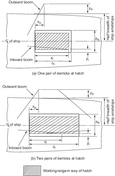
Figure 2.4.2 Positions of derricks for union
purchase
4.2.4 Calculations
of the forces and resultant loads in the system are to be made as
follows:
-
Based on maximum headroom:
-
Based on maximum included
runner angle:
4.2.5 Where, at
the request of the Owner, the rig is to operate over a working range
different from that given in Ch 2, 4.2 Working range of the rig 4.2.2,
including instances where the rig is designed for use in one fixed
position only, calculations are to be made for the extreme positions
of the specified range. The boom positions are to be clearly defined
in the Register of Ship’s Lifting Appliances and Cargo
Handling Gear. In all instances, the arrangement is to comply
with the limiting criteria given in Ch 2, 4.1 General 4.1.5.
4.2.6 It may be
assumed that the maximum forces will be associated with the extreme
positions of the rig. Intermediate positions within the working range
need not, in general, be examined.
4.2.7 The derrick
booms are to be restrained by the use of preventer guys which are
to be attached to eyeplates at the boom head or looped over the boom.
The slewing guys are to be slackened off once the rig is set up and
only the preventer guys are to be taken into account with regard to
the calculation of forces in the rig.
4.2.8 It is recommended
that the deck eyeplate for the preventer to the inboard derrick should
be approximately abreast the derrick head. The eyeplate for the preventer
to the outboard derrick is to be positioned so as to obviate the risk
of jack-knifing, see
Figure 2.4.5 Form of diagram when beam is in
danger of jack-knifing, and to avoid excessive guy tension.
4.2.9 The boom heads
are to be connected by a boom head or schooner guy, the safe working
load of which is to be as required by Ch 2, 8.4 Slewing and preventer guys 8.4.6.
Alternative arrangements will be considered.
4.3 Calculation of forces
4.3.1 The dimensions
and other particulars required for the calculation of forces in the
rig are indicated in Figure 2.4.3 Typical data sheet.
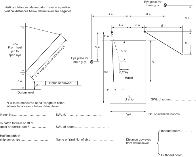
Figure 2.4.3 Typical data sheet
4.3.2 Where the
forces are to be determined by the construction of force diagrams,
it is recommended that the following procedure be adopted, corresponding
to the parts of the typical diagrams as labelled in Figure 2.4.4 Typical union purchase
calculations:
-
Projected plan of the
rig.
-
True side elevations
of the derrick booms.
-
Lines of the cargo runners
at the minimum headroom position.
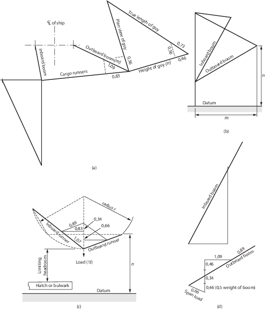
Figure 2.4.4 Typical union purchase
calculations
4.3.4 Where a diagram
of the character shown in Figure 2.4.5 Form of diagram when beam is in
danger of jack-knifing is
obtained (this is where the diagram does not ‘close’),
the boom is in danger of jack-knifing. The boom will be in danger
of jack-knifing if the total vertical load is less than the span tension
x tan α, where α is the angle of the boom to the horizontal.
Where this situation arises, the eyeplates for the preventer guys
are to be repositioned. In general, it is recommended that the position
of the guy eyeplate for the outboard boom is such that the load due
to the vertical components of the runner and guy forces (but not the
boom weight) is at least equal to span tension x tan α.
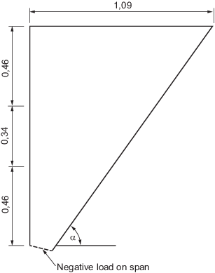
Figure 2.4.5 Form of diagram when beam is in
danger of jack-knifing
4.3.5 As an alternative
to the graphical procedure, the forces in the rig may be determined
by direct calculation.
|
| Copyright 2022 Clasifications Register Group Limited, International Maritime Organization, International Labour Organization or Maritime
and Coastguard Agency. All rights reserved. Clasifications Register Group Limited, its affiliates and subsidiaries and their respective
officers, employees or agents are, individually and collectively, referred to in this clause as 'Clasifications Register'. Clasifications
Register assumes no responsibility and shall not be liable to any person for any loss, damage or expense caused by reliance
on the information or advice in this document or howsoever provided, unless that person has signed a contract with the relevant
Clasifications Register entity for the provision of this information or advice and in that case any responsibility or liability is
exclusively on the terms and conditions set out in that contract.
|
 |
|