
Section
8 Fittings for masts and derrick booms
8.1 General
8.1.1 The application
of fixed fittings, ropes and loose gear in derrick systems is to comply
with the requirements of this Section. The items themselves are to
be manufactured in accordance with the requirements given in Ch 8 Fittings, Loose Gear and Ropes.
8.1.2 Effective
continuity of materials is to be maintained in the bearing brackets
for fittings and abrupt changes of plate thickness are to be avoided.
Care is to be taken to avoid pockets in which water may collect. The
connection to the mast or derrick boom is to provide an easy transfer
of load into the surrounding structure and to minimise hard spots
and sources of stress concentration.
8.1.3 All welds
are to be sound, uniform and free from undercutting or other defects.
Care is to be taken to ensure adequate weld penetration. Effective
arrangements are to be made for the inspection of finished welds.
The extent of examination by non-destructive methods is to be to the
Surveyor’s satisfaction.
8.1.4 All bearing
surfaces are to be machined to ensure a smooth finish and a good fit.
Adequate and accessible means of lubrication are to be provided.
8.2 Goosenecks and derrick heel assemblies
8.2.1 The gooseneck
bearing assembly is to be such that:
-
The gooseneck pin is
secured in position to prevent displacement under normal operating
conditions.
-
Brackets and supporting
structure are adequate to support the forces from the derrick boom
operating at the maximum and minimum angles. Edges of brackets are
to be stiffened as necessary to resist distortion.
-
Where the gooseneck
is supported by a mast, a diaphragm or equivalent stiffening is fitted,
or the width of brackets or other attachments is not less than two
thirds of the diameter of the mast at that level.
8.2.2 Derrick heel
fittings are to be such that:
-
The axis of the derrick
heel crosspin cuts the axis of the derrick boom. Design incorporating
a small offset will be specially considered.
-
The derrick heel crosspin
is secured to prevent displacement under normal operating conditions.
8.2.3 Trunnions
and other alternatives to goosenecks will be specially considered.
8.2.4 Adequate means
are to be provided for the lubrication of all bearing surfaces and
their protection from contamination by dirt or excessive water. Such
protection is not to make inspection of the assembly unreasonably
difficult.
8.3 Cargo runner and span tackle
8.3.1 The cargo
runner is to be of sufficient length to ensure that with the derrick
rigged for lifting, the maximum safe working load is to be that at
least two turns remain on the winch barrel when the derrick is at
either:
-
its highest working
position and lifting from the tank top or lowest level from which
it can be operated;
-
its maximum overside
position and lifting from a lighter with the ship at its light waterline.
The cargo runner is to be securely attached to the winch barrel.
8.3.2 The length
of the span tackles is to be such that at least two turns remain on
the winch barrel when the derrick is at its position of maximum outreach,
or one turn when the derrick is in its stowed position. Where single
rope spans are fitted, the span rope may be led to a topping winch
or be fitted with a span chain securely attached to the deck eyeplates
by a shackle or screw pin. Where span chains are fitted, the links
are to be of sufficient size that the eye of a shackle can be passed
through. Where the span rope is more than one part, it is to be led
to a winch barrel or topping winch and securely attached to it.
8.4 Slewing and preventer guys
8.4.1 In general,
each derrick boom is to be provided with two slewing guys where the
SWL of the derrick does not exceed 20 tonnes or three guys for derricks
with higher safe working loads. The safe working load of each guy
is to be not less than that required by Table 2.8.1 SWL of derrick boom slewing
guys. Where three guys are required, deck fittings are to
be provided so that two guys can be used on each side of the ship.
For slewing guys used with derrick cranes, see
Ch 2, 5.3 Slewing guys 5.3.3.
Table 2.8.1 SWL of derrick boom slewing
guys
SWL of derrick rig
not
exceeding, tonnes
|
SWL of each slewing guy,
tonnes
|
| 1
|
1
|
| 2
|
1,5
|
| 3
|
2
|
| 4
|
2,5
|
| 5
|
3
|
| 6
|
3,25
|
| 9,5
|
3,5
|
| 12,5
|
3,75
|
| 15
|
4
|
| 60
|
25% of derrick SWL
|
| 75
|
15
|
| over 75
|
20% of derrick SWL
|
8.4.2 Where the
angle of the heel or trim in the operating condition exceeds 5°
or 2° respectively, the requirements for slewing guys will be
considered.
8.4.3 Alternative
arrangements of slewing guys and proposals for reduced slewing guys
where cargo slewing guys are fitted will be specially considered.
Such arrangements are to be capable of operating at 5° heel and
2° trim or at greater angles where specified.
8.4.4 Natural or
man-made fibre ropes may be used in the guy tackle (but not the guy
pendant) provided the SWL of the guy does not exceed 4 t.
8.4.5 Where derricks
are rigged for use in union purchase, preventer guys are to be fitted
in addition to slewing guys. Preventer guys are to have a safe working
load not less than the maximum guy tension derived from Ch 2, 4.3 Calculation of forces. Fibre rope is not to be used for preventer
guys.
8.4.6 Boom head
or schooner guys used for crossconnecting the heads of derricks in
union purchase are to have a safe working load not less than 20 per
cent of the SWL of the union purchase system, and not less than 1,0
t. These guys may be of steel wire or of fibre rope.
8.4.7 The hauling
end of wire rope slewing guys is to be securely attached to a winch
barrel when the derrick is being slewed under load.
8.4.8 Slewing guys
are to be attached to the derrick boom and the deck eyeplate by a
link, shackle or similar device so designed as to permit the guy to
take up its varying positions while maintaining a straight lead. Leads
are to be such that the guys will not foul rails, bulwarks or other
obstructions when under load. Fairleads may be used.
8.4.9 Preventer
guys are to be shackled on, or looped over the derrick head and shackled,
or equivalent, to eyeplates on the deck or bulwark.
8.5 Swivelling and fixed eyeplates
8.5.1 Swivelling
eyeplates are to be used for the attachment of span tackle and cargo
runner lead blocks to the mast for all derricks where the safe working
load is 3,0 t or more or where the load in the span tackle exceeds
5,0 t. They may also be used elsewhere.
8.5.2 Fixed eyeplates
at the derrick head may be of the ’sword-fitting’ type,
providing a pair of eyeplates on opposite sides of the derrick tube,
or the fitting may penetrate one side of the tube and be securely
attached to internal structure.
8.6 Blocks
8.6.1 Swivels are
to be arranged, as necessary, to ensure that blocks maintain their
correct alignment.
8.6.2 The cargo
runner lead block at the derrick heel is to have a duckbill or similar
head fitting which prevents the block falling when the cargo runner
is slack. This is to be arranged so as to allow the heel block to
clear the derrick tube when the derrick tube is in its stowed position.
8.6.3 Snatch blocks
may only be used as deck lead blocks.
8.6.4 Wood blocks
may only be used with fibre ropes.
8.7 Cargo hooks
8.7.1 Cargo hooks
are to be of such construction or shape, or are to be provided with
an efficient device, so as to prevent displacement of the sling or
load from the hook.
8.7.2 In general,
‘C’, (or Liverpool) type hooks may be used where the SWL
of the derrick rig does not exceed 25 t. Cargo hooks of the Ramshorn
type may be used in rigs of any SWL. Proposals to use other designs
of hook will be considered.
8.8 Miscellaneous fittings
8.8.1 Where built-in
sheaves are fitted to the derrick boom, the design of the sheave slot
is to be such as to maintain continuity of strength of the boom tube.
A typical arrangement is shown in Figure 2.8.1 Built-in sheaves but alternative arrangements will be considered.
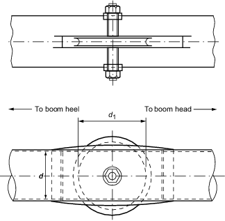
Figure 2.8.1 Built-in sheaves
8.8.2 Where cargo
runner roller guides are fitted to the derrick boom, they are to be
such that:
-
They are of adequate
strength to resist distortion.
-
Any tendency for the
runner to chafe or jam in or between the rollers and their supports
is minimised.
-
There is adequate means
of lubrication.
8.8.3 Where it is
intended to loop preventer guys over the end of a derrick boom, a
preventer safety catch is to be securely welded or otherwise fixed
to the boom. This safety catch can take the form of the boom end sealing
plate being extended, over part of its circumference, beyond the outer
surface of the boom tube, or alternatively, a separate fitting can
be used. Edges are to be smoothed.
8.9 Deck eyeplates
8.9.1 Sufficient
eyeplates or equivalent attachments are to be provided for the safe
operation of the derrick system and they are to be of suitable design
and safe working load.
8.9.2 Eyeplates
are not to be welded to the upper edge of the sheerstrake nor, in
general, are they to penetrate the strength deck plating. Deck, bulwark
or other plating is to be of sufficient thickness to withstand any
shear forces that may be incurred in way of eyeplates due to asymmetrical
loading of the eyeplate, and such plating is to be stiffened as necessary
to prevent deformation under direct eyeplate loadings. The attachment
of eyeplates and the adequacy of the supporting structure are to be
to the Surveyor’s satisfaction.
|
| Copyright 2022 Clasifications Register Group Limited, International Maritime Organization, International Labour Organization or Maritime
and Coastguard Agency. All rights reserved. Clasifications Register Group Limited, its affiliates and subsidiaries and their respective
officers, employees or agents are, individually and collectively, referred to in this clause as 'Clasifications Register'. Clasifications
Register assumes no responsibility and shall not be liable to any person for any loss, damage or expense caused by reliance
on the information or advice in this document or howsoever provided, unless that person has signed a contract with the relevant
Clasifications Register entity for the provision of this information or advice and in that case any responsibility or liability is
exclusively on the terms and conditions set out in that contract.
|
 |
|