5.2.1 Twin span
tackles are to include:
-
Two separate span tackles
each attached to the head of the boom, directly or via outriggers,
and operated by independent winches.
-
Two span tackles led
to a topping winch and a slewing winch. The topping winch shortens
equally on both spans and the slewing winch shortens one span while
paying out the other, see
Figure 2.5.1 Span tackles with winch.
The two sections of the tackles may be attached to the cross
trees of a mast or they may be fitted to two separate derrick posts.
Where two separate posts are used, the boom is sometimes arranged
so that it can pass through the vertical position between the posts
and so be available to work hatches both forward and aft of the posts.
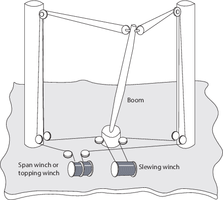
Figure 2.5.1 Span tackles with winch
5.2.2 Where twin
span tackles are fitted, they are to be so arranged that the minimum
distance of the span tackle from the vertical through the boom gooseneck
is not less than one ninth of the boom length. This distance is to
be measured horizontally at right angles to the line of action of
the span tackle, or to the section of the span tackle under consideration, see
Figure 2.5.2 Minimum separation. This minimum
separation can be achieved by one or more of the following means:
-
by limiting the slewing
angle of the boom; or
-
by fitting outriggers
to the boom head; or
-
by fitting hinged or
fixed outriggers, or their equivalent to the derrick posts, mast house
or cross tree; or
-
by a combination of
one or more of the above.
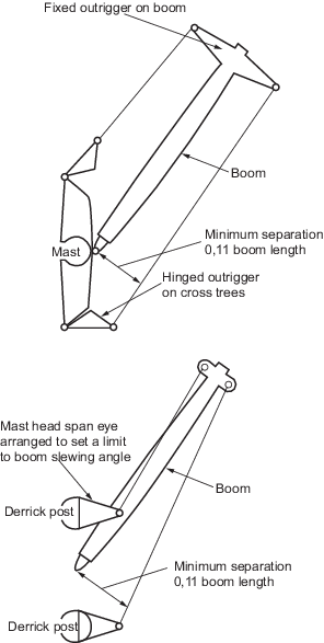
Figure 2.5.2 Minimum separation
5.2.3 Alternatively,
the stability of the system may be demonstrated by calculation or
by model tests.
5.2.4 Where the
slewing angle of the boom is to be restricted, this may be done by
moving the position of the mast head span eyeplate away from the transverse
plane through the gooseneck into a position that will be vertically
above the derrick boom when the boom is in its limiting position.
Alternatively, limit switches may be installed to provide automatic
cut-out of the slewing system. Limiting the slewing angle of the boom
by means of a stop fitted to the boom heel or by allowing the boom
to come up against a shroud or other obstruction cannot normally be
recommended as these methods tend to induce large transverse bending
moments in the boom or to cause local indentations and consequential
failure of the boom tube.
5.2.5 In general,
where twin span tackles are fitted, the strength of each is to be
sufficient to support the boom plus the safe working load in the boom’s
fully outboard position. Where, however, it can be shown that it is
not possible for either span tackle to become slack in service, the
strength of each tackle may be based on the maximum calculated span
tension but is to be taken as not less than two thirds of the total
span tension. Calculations in this respect are to be submitted by
the manufacturer of the derrick crane.
5.2.6 Where the
derrick boom is fitted with a cross-head and the span tackles are
each connected by strops to both ends of the cross-head, then the
required breaking load of each of the strops may be based upon 80
per cent of the maximum load in the span tackle.