
Section
6 Derrick booms
6.1 General
6.1.1 The requirements
of this Section are applicable to the following types of tubular derrick
boom:
-
Parallel boom.
A boom which is of uniform diameter and thickness over its full length.
-
Tapered boom.
A boom which has a mid-section of uniform diameter and thickness welded
to tapered end sections.
-
Stepped boom.
A boom which has a mid-section of uniform diameter and thickness reducing
towards the ends in one or more steps. The change of section may be
obtained by cressed, lapped or stepped construction.
6.1.2 Proportions
for tapered and stepped derrick’s booms are illustrated in Figure 2.6.1 Forms of booms. Alternative arrangements will,
however, be accepted where it may be shown that the resulting strength
of the boom is adequate. Derricks of unusual design or incorporating
special features will be considered on the general basis of these
requirements.
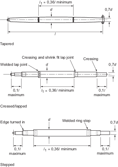
Figure 2.6.1 Forms of booms
6.1.3 The scantlings
of derrick booms are to be determined on the basis of the axial thrust
and the maximum combination of bending moments applied to the boom,
as derived from the force diagrams and calculations for the derrick
system.
6.1.4 Steel for
derrick booms is to comply with the requirements of Ch 2, 1.5 Materials 1.5.3. Derrick booms intended for a SWL
of 60t or more are to be suitably heat-treated after welding where
considered necessary. For mild steel booms, this may normally be confined
to the region of highly loaded welded connections. The requirements
for higher tensile steel booms will depend on the materials specification.
6.2 Determination of forces
6.2.2 The bending
moments acting on the boom are to be calculated for conditions with
the boom in its lowest and its highest working positions.
6.2.3 The determination
of vertical end bending moments for typical derrick head arrangements
is illustrated in Figure 2.6.2 Determination of end bending
moment. The
bending moment is to be calculated approximately at the point of intersection
of the axis of the boom with the line joining the points of action
of the cargo and span loads and this may be taken as reducing linearly
from this point to zero at the derrick heel.
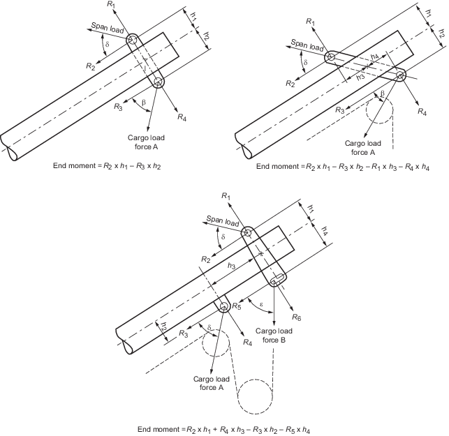
Figure 2.6.2 Determination of end bending
moment
6.2.4 For built-in
sheaves, where the sheave pin intersects the axis of the boom, the
value of h is to be taken as zero.
6.2.5 Horizontal
bending moments arising from slewing or preventer guys attached to
the derrick boom head may generally be neglected.
6.2.6 Where the
derrick is fitted with a cross-head or outrigger, consideration is
to be given to the bending and torsional moments which may arise where
the span force is not equally distributed between the span tackles.
In general, the boom is to be designed to resist the bending moments
induced when supported by one span tackle only.
6.3 Boom scantlings
6.3.1 The following
symbols are used in this sub-Section:
|
d
|
= |
external
diameter of the boom in the mid length region, in mm |
|
l |
= |
overall
length of the derrick boom, in mm |
|
l1
|
= |
length
of the parallel part of the boom, in mm |
|
r
|
= |
effective
radius of gyration of the boom, in mm |
|
t
|
= |
wall
thickness of the boom in the mid length region, in mm |
|
A
|
= |
cross-sectional
area of material of the boom in the mid length region, in mm2
|
|
Ae
|
= |
cross-sectional area of material of the boom at the boom head,
in mm2
|

|
= |
moment of inertia of the
boom in the mid length region, in mm4
|

|
= |
moment of inertia of the
boom at the head, in mm4
|
|
Z
|
= |
section
modulus of the boom in the mid length region, in mm3
|
|
Ze
|
= |
section modulus of the boom at the boom head, in mm3.
|
6.3.2 The slenderness
ratio  of the boom is not to exceed 180. It is recommended that
the slenderness ratio be less than 150. of the boom is not to exceed 180. It is recommended that
the slenderness ratio be less than 150.
6.3.3 The wall thickness
of the boom at mid length is to be not less than:
The wall thickness at ends is to be such that the
cross-sectional area of material is not less than 0,75A.
6.3.4 The moment of inertia at the derrick head,  , is to be not less than 0,40 , is to be not less than 0,40 . .
6.3.5 Where the
derrick boom is tapered or stepped, an effective radius of gyration, r, is to be determined from:
where
|
c
|
= |

|
|
u
|
= |

|
Where l1 is greater than 0,5l the value
of c is to be obtained by interpolation between c calculated
for l1 = 0,5l and c = 1 at l1 = 0,8l.
6.3.7 Where significant
horizontal bending moments are likely to be applied to the boom, they
are to be taken into account in the calculation.
6.3.8 The critical
stress, σ, in N/mm2 for the derrick boom is to be determined
from:
6.3.9 The maximum
allowable thrust, T, in the boom is to be determined
from the critical stress and a factor of safety, F, such
that:
where
|
A
x
|
= |
the cross-sectional area of material at the section under
consideration, in mm2
|
|
F |
= |
(i) at mid length but 2,333 ≤ F ≤ 3,85 but 2,333 ≤ F ≤ 3,85 |
| = |
(ii) at ends 1,85 |
| = |
(iii) at intermediate positions:
by parabolic interpolation
between the values at mid-length and at the boom head. |
6.3.10 Where T lies
between 10 and 160 tonnes, the value T for the mid length
region may be determined from:
6.3.11 For the
purpose of making a first approximation to the required scantlings
for a boom, thrust coefficients are tabulated in Table 2.6.1 Boom thrust coefficients (mild
steel σy = 235 N/mm2) and Table 2.6.2 Boom thrust coefficients (high
tensile steel σy = 355 N/mm2) . The maximum allowable thrust, before making allowance
for applied bending moments, is approximately:
Having selected a suitable boom diameter and wall
thickness, the allowable thrust, taking into account the applied bending
moment, is to be determined in accordance with the method given above.
Table 2.6.1 Boom thrust coefficients (mild
steel σy = 235 N/mm2)
| Boom diameter, in
mm
|
Boom length, in metres
|
|
|
| 6,0
|
7,5
|
9,0
|
10,5
|
12,0
|
13,5
|
15,0
|
16,5
|
18,0
|
19,5
|
21,0
|
| 152,4
|
1,36
|
0,94
|
0,68
|
—
|
—
|
—
|
—
|
—
|
—
|
—
|
—
|
| 159,0
|
1,55
|
1,06
|
0,77
|
—
|
—
|
—
|
—
|
—
|
—
|
—
|
—
|
| 165,1
|
1,73
|
1,18
|
0,86
|
—
|
—
|
—
|
—
|
—
|
—
|
—
|
—
|
|
|
|
|
|
|
|
|
|
|
|
|
|
| 168,3
|
1,83
|
1,25
|
0,91
|
0,70
|
—
|
—
|
—
|
—
|
—
|
—
|
—
|
| 177,8
|
2,14
|
1,48
|
1,07
|
0,82
|
—
|
—
|
—
|
—
|
—
|
—
|
—
|
| 193,7
|
2,71
|
1,93
|
1,39
|
1,05
|
0,83
|
—
|
—
|
—
|
—
|
—
|
—
|
|
|
|
|
|
|
|
|
|
|
|
|
|
| 219,1
|
3,71
|
2,78
|
2,05
|
1,53
|
1,19
|
0,96
|
—
|
—
|
—
|
—
|
—
|
| 244,5
|
4,78
|
3,77
|
2,87
|
2,19
|
1,70
|
1,34
|
1,10
|
—
|
—
|
—
|
—
|
| 267,0
|
5,75
|
4,72
|
3,72
|
2,88
|
2,25
|
1,79
|
1,45
|
1,20
|
—
|
—
|
—
|
|
|
|
|
|
|
|
|
|
|
|
|
|
| 273,0
|
6,02
|
4,99
|
3,96
|
3,09
|
2,42
|
1,93
|
1,56
|
1,29
|
—
|
—
|
—
|
| 298,5
|
7,14
|
6,14
|
5,05
|
4,05
|
3,22
|
2,58
|
2,10
|
1,73
|
1,45
|
—
|
—
|
| 323,9
|
8,27
|
7,30
|
6,21
|
5,12
|
4,15
|
3,36
|
2,74
|
2,27
|
1,90
|
1,61
|
1,38
|
|
|
|
|
|
|
|
|
|
|
|
|
|
| 355,6
|
9,69
|
8,77
|
7,71
|
6,57
|
5,47
|
4,51
|
3,72
|
3,09
|
2,60
|
2,20
|
1,89
|
| 368,0
|
10,25
|
9,35
|
8,30
|
7,16
|
6,03
|
5,01
|
4,16
|
3,47
|
2,91
|
2,47
|
2,18
|
| 406,4
|
11,99
|
11,14
|
10,15
|
9,03
|
7,85
|
6,71
|
5,67
|
4,79
|
4,05
|
3,45
|
2,96
|
|
|
|
|
|
|
|
|
|
|
|
|
|
| 419,0
|
12,57
|
11,73
|
10,76
|
9,65
|
8,47
|
7,30
|
6,22
|
5,27
|
4,48
|
3,82
|
3,29
|
| 457,2
|
14,31
|
13,52
|
12,60
|
11,55
|
10,39
|
9,18
|
7,99
|
6,90
|
5,93
|
5,11
|
4,41
|
| 508,0
|
16,65
|
15,89
|
15,03
|
14,06
|
12,96
|
11,77
|
10,53
|
9,32
|
8,18
|
7,15
|
6,24
|
|
|
|
|
|
|
|
|
|
|
|
|
|
| 558,8
|
18,80
|
18,19
|
17,46
|
16,55
|
15,52
|
14,39
|
13,18
|
11,92
|
10,67
|
9,50
|
8,41
|
| 609,6
|
20,75
|
20,17
|
19,53
|
18,81
|
18,02
|
16,99
|
15,83
|
14,59
|
13,32
|
12,06
|
10,85
|
Note Intermediate values may be obtained by interpolation but
extrapolation is not permitted.
|
Table 2.6.2 Boom thrust coefficients (high
tensile steel σy = 355 N/mm2)
| Boom diameter, in
mm
|
Boom length, in metres
|
|
|
| 6,0
|
7,5
|
9,0
|
10,5
|
12,0
|
13,5
|
15,0
|
16,5
|
18,0
|
19,5
|
21,0
|
| 152,4
|
1,56
|
1,01
|
0,72
|
—
|
—
|
—
|
—
|
—
|
—
|
—
|
—
|
| 159,0
|
1,80
|
1,15
|
0,82
|
—
|
—
|
—
|
—
|
—
|
—
|
—
|
—
|
| 165,1
|
2,04
|
1,30
|
0,92
|
—
|
—
|
—
|
—
|
—
|
—
|
—
|
—
|
|
|
|
|
|
|
|
|
|
|
|
|
|
| 168,3
|
2,17
|
1,39
|
0,98
|
0,73
|
—
|
—
|
—
|
—
|
—
|
—
|
—
|
| 177,8
|
2,61
|
1,67
|
1,15
|
0,87
|
—
|
—
|
—
|
—
|
—
|
—
|
—
|
| 193,7
|
3,45
|
2,24
|
1,54
|
1,12
|
0,88
|
—
|
—
|
—
|
—
|
—
|
—
|
|
|
|
|
|
|
|
|
|
|
|
|
|
| 219,1
|
5,05
|
3,40
|
2,35
|
1,70
|
1,28
|
1,02
|
—
|
—
|
—
|
—
|
—
|
| 244,5
|
6,88
|
4,86
|
3,42
|
2,48
|
1,87
|
1,45
|
1,16
|
—
|
—
|
—
|
—
|
| 267,0
|
8,60
|
6,39
|
4,61
|
3,37
|
2,53
|
1,97
|
1,57
|
1,28
|
—
|
—
|
—
|
|
|
|
|
|
|
|
|
|
|
|
|
|
| 273,0
|
9,07
|
6,83
|
4,96
|
3,64
|
2,74
|
2,12
|
1,69
|
1,38
|
—
|
—
|
—
|
| 298,5
|
11,05
|
8,77
|
6,13
|
4,94
|
3,74
|
2,90
|
2,31
|
1,87
|
1,55
|
—
|
—
|
| 323,9
|
13,00
|
10,79
|
8,47
|
6,48
|
4,97
|
3,87
|
3,08
|
2,49
|
2,06
|
1,73
|
1,47
|
|
|
|
|
|
|
|
|
|
|
|
|
|
| 355,6
|
15,41
|
13,35
|
10,98
|
8,70
|
6,82
|
5,37
|
4,28
|
3,47
|
2,86
|
2,39
|
2,03
|
| 368,0
|
16,34
|
14,34
|
11,99
|
9,65
|
7,63
|
6,04
|
4,83
|
3,92
|
3,23
|
2,70
|
2,29
|
| 406,4
|
18,96
|
17,39
|
15,16
|
12,73
|
10,41
|
8,42
|
6,83
|
5,58
|
4,61
|
3,85
|
3,26
|
|
|
|
|
|
|
|
|
|
|
|
|
|
| 419,0
|
19,73
|
18,28
|
16,20
|
13,77
|
11,39
|
9,29
|
7,57
|
6,21
|
5,14
|
4,30
|
3,64
|
| 457,2
|
22,03
|
20,71
|
19,07
|
16,99
|
14,51
|
12,15
|
10,09
|
8,38
|
6,99
|
5,87
|
4,98
|
| 508,0
|
25,04
|
23,85
|
22,40
|
20,64
|
18,64
|
16,31
|
13,93
|
11,81
|
10,00
|
8,49
|
7,25
|
|
|
|
|
|
|
|
|
|
|
|
|
|
| 558,8
|
28,02
|
26,92
|
25,61
|
24,04
|
22,20
|
20,16
|
18,08
|
15,73
|
13,56
|
11,68
|
10,07
|
| 609,6
|
30,97
|
29,95
|
28,74
|
27,32
|
25,64
|
23,74
|
21,68
|
19,59
|
17,55
|
15,35
|
13,40
|
Note Intermediate values may be obtained by interpolation but
extrapolation is not permitted.
|
6.4 Construction details
6.4.1 In way of
head and heel fittings, the wall thickness is to be not less than
5,0 mm or 0,025 x tube diameter at that point, whichever is the greater.
Proposals to fit stiffening in lieu of increased plate thickness to
meet this requirement will be considered.
6.4.2 Where internal
access for welding of the derrick tube is impracticable, means of
obtaining full penetration welds are to be agreed.
6.4.3 Lap joints
are to be not less than half the boom diameter at that point in extent.
Where the lap is welded, this is to be achieved by slot welds of at
least 75 mm length and twice the boom wall thickness (but not less
than 25 mm) in breadth. Where step joints are adopted, the inner tube
is to extend into the outer tube a distance of not less than the diameter
of the outer tube or 450 mm, whichever is the lesser. The end of the
inner tube is to be stiffened by a steel ring not less than 40 mm
in width and of thickness sufficient to give a sliding fit within
the outer tube, see
Figure 2.6.3 Steps and joints in booms.
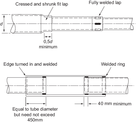
Figure 2.6.3 Steps and joints in booms
6.4.4 Welds are
to be sound, uniform and substantially free from defects. The throat
thickness of fillet welds on lapped joints is to be not less than
0,7 times the thickness of the inner plate forming the joint.
6.4.5 Derrick booms
are to be sealed to minimise corrosion to their internal surfaces.
Where practicable, derrick booms are to be painted internally or otherwise
treated to reduce corrosion, after the completion of all welding.
6.4.6 Derrick boom
cross-heads, brackets for cargo runner and span tackle blocks and
similar structures are to be of such a design that the combined stress
does not exceed 0,56σy.
|