
Section
5 Loose gear
5.1 Shackles
5.1.1 The safe working
load of any shackle securing a block is to be not less than the SWL
marked on the block, except in the case of single sheave blocks where
the SWL is to be not less than twice that marked on the block.
5.1.2 The safe working
load of any shackle used in another location is to be not less than
the resultant load on the shackle.
5.1.3 Mild steel
shackles are to be normalised after forging and before tapping and
screwing. Higher tensile and alloy steel shackles are to be subjected
to a suitable heat treatment.
5.1.4 Standard dimensions
of Dee and Bow shackles are given for reference in Table 8.5.1 Dimensions of Dee shackles and Table 8.5.2 Dimensions of Bow shackles for the arrangements illustrated in Figure 8.5.1 Shackles.
Table 8.5.1 Dimensions of Dee shackles
| Safe working load, in tonnes
|
|
|
Mild steel
|
Higher tensile steel
|
|
a
|
b
|
d
1
|
d
2
|
d
1
|
d
2
|
| 1,0
|
20
|
44
|
13
|
15
|
11
|
12
|
| 1,6
|
25
|
55
|
17
|
19
|
13
|
15
|
| 2,0
|
28
|
62
|
19
|
21
|
15
|
17
|
| 2,5
|
31
|
69
|
21
|
24
|
17
|
19
|
| 3,2
|
35
|
78
|
24
|
27
|
19
|
21
|
| 4,0
|
40
|
87
|
26
|
30
|
21
|
23
|
| 5,0
|
44
|
97
|
29
|
33
|
23
|
26
|
| 6,3
|
50
|
109
|
33
|
37
|
26
|
29
|
| 8,0
|
56
|
123
|
37
|
42
|
29
|
33
|
| 10,0
|
63
|
138
|
41
|
47
|
33
|
37
|
| 12,5
|
70
|
154
|
46
|
53
|
36
|
42
|
| 16,0
|
79
|
174
|
52
|
60
|
41
|
47
|
| 20,0
|
89
|
195
|
59
|
67
|
46
|
52
|
| 25,0
|
99
|
218
|
65
|
75
|
51
|
59
|
| 32,0
|
112
|
247
|
74
|
84
|
58
|
66
|
| 40,0
|
125
|
275
|
83
|
94
|
65
|
74
|
| 50,0
|
140
|
308
|
92
|
106
|
72
|
83
|
| 63,0
|
157
|
346
|
104
|
119
|
81
|
93
|
| 80,0
|
177
|
390
|
117
|
134
|
91
|
105
|
Note
2. Higher tensile steel is defined as
steel having a tensile strength not less than 540 N/mm2.
Note
3. Diameter d
3 is to be not less than 2d
2.
|
Table 8.5.2 Dimensions of Bow shackles
| Safe working load,
in tonnes
|
|
|
|
Mild steel
|
Higher tensile steel
|
|
a
|
b
|
2r
|
d
1
|
d
2
|
d
1
|
d
2
|
| 1,0
|
20
|
50
|
34
|
14
|
16
|
12
|
13
|
| 1,6
|
25
|
63
|
43
|
18
|
20
|
15
|
16
|
| 2,0
|
28
|
70
|
48
|
20
|
22
|
17
|
18
|
| 2,5
|
31
|
78
|
53
|
23
|
25
|
18
|
20
|
| 3,2
|
35
|
89
|
60
|
25
|
28
|
21
|
22
|
| 4,0
|
40
|
99
|
67
|
28
|
31
|
23
|
25
|
| 5,0
|
44
|
111
|
75
|
32
|
35
|
26
|
28
|
| 6,3
|
50
|
124
|
84
|
36
|
39
|
29
|
32
|
| 8,0
|
56
|
140
|
95
|
40
|
44
|
33
|
36
|
| 10,0
|
63
|
157
|
106
|
45
|
49
|
36
|
40
|
| 12,5
|
70
|
175
|
119
|
50
|
55
|
41
|
44
|
| 16,0
|
79
|
198
|
135
|
56
|
62
|
46
|
50
|
| 20,0
|
89
|
221
|
150
|
63
|
69
|
51
|
56
|
| 25,0
|
99
|
248
|
168
|
70
|
77
|
57
|
63
|
| 32,0
|
112
|
280
|
190
|
80
|
87
|
65
|
71
|
| 40,0
|
125
|
313
|
213
|
89
|
98
|
72
|
79
|
| 50,0
|
140
|
350
|
248
|
99
|
109
|
81
|
89
|
| 63,0
|
157
|
394
|
267
|
112
|
123
|
91
|
100
|
| 80,0
|
177
|
444
|
301
|
126
|
138
|
102
|
112
|
Note
2. Higher tensile steel is defined as
steel having a tensile strength not less than 540 N/mm2.
Note
3. Diameter d
3 is to be not less than 2d
2.
|

Figure 8.5.1 Shackles
5.1.5 Where the
shackle is not manufactured in accordance with a recognised Standard,
the safe working load may be taken as the lowest of the values derived
from the following formulae:
Side of body:
Crown of body:
Shackle pin:
where all dimensions are in millimetres and are illustrated
in Figure 8.5.1 Shackles. The value of c is
given in Table 8.5.3 Values of c for
shackles.
Table 8.5.3 Values of c for
shackles
Minimum
tensile
strength of steel, in
N/mm2
|
c
|
| Side
|
Crown
|
Pin
|
| 330
|
0,0076
|
0,0082
|
0,0072
|
| 430
|
0,0105
|
0,0113
|
0,0099
|
| 540
|
0,0140
|
0,0151
|
0,0132
|
5.2 Hooks
5.2.1 The safe working
load of a hook is the maximum load that the hook is certified to lift
in service.
5.2.2 Hooks may
be of the ‘C’ or Liverpool type or of the double armed
Ramshorn type, as indicated in Figure 8.5.2 Hooks.
In general, ‘C’ type hooks are not to be used for safe
working loads exceeding 25t. Hooks manufactured to recognised
National or International Standards could be accepted based on manufacturer’s
certification confirming the SWL and proof load as per Ch 12 Testing, Marking and Surveys of the Code. Hooks with a SWL beyond
those given in Table 8.5.4 Dimensions of higher tensile steel
‘C’ hooks or Table 8.5.5 Dimensions of higher tensile steel
Ramshorn hooks and/or hooks which do not comply
with a recognised National or International Standard will be specially
considered.

Figure 8.5.2 Hooks
Table 8.5.4 Dimensions of higher tensile steel
‘C’ hooks
Safe working load,
in tonnes
|
a
|
b
|
c
|
D
|
H
|
M
|
G
|
| 1,0
|
124
|
78
|
6
|
31
|
26
|
17
|
17
|
| 1,6
|
156
|
98
|
8
|
39
|
33
|
21
|
20
|
| 2,0
|
176
|
110
|
8
|
44
|
37
|
24
|
25
|
| 2,5
|
196
|
123
|
10
|
49
|
41
|
27
|
25
|
| 3,2
|
219
|
138
|
12
|
55
|
46
|
30
|
30
|
| 4,0
|
247
|
156
|
12
|
62
|
52
|
34
|
30
|
| 5,0
|
279
|
176
|
14
|
70
|
59
|
38
|
35
|
| 6,3
|
311
|
196
|
16
|
78
|
66
|
43
|
40
|
| 8,0
|
351
|
221
|
18
|
88
|
74
|
48
|
45
|
| 10,0
|
391
|
246
|
20
|
98
|
82
|
54
|
50
|
| 12,5
|
439
|
276
|
22
|
110
|
92
|
60
|
55
|
| 16,0
|
495
|
311
|
24
|
124
|
104
|
68
|
60
|
| 20,0
|
555
|
349
|
28
|
139
|
117
|
76
|
70
|
| 25,0
|
622
|
392
|
32
|
156
|
131
|
86
|
80
|
Note
1. All dimensions are given in
millimetres and are illustrated in Figure 8.5.2 Hooks.
Note
2. Minimum material tensile strength
σu 540 N/mm2.
|
Table 8.5.5 Dimensions of higher tensile steel
Ramshorn hooks
Safe working load,
in tonnes
|
a
|
b
|
c
|
D
|
H
|
M
|
G
|
| 20
|
238
|
457
|
30
|
121
|
113
|
76
|
89
|
| 25
|
267
|
511
|
33
|
133
|
126
|
86
|
102
|
| 32
|
299
|
567
|
37
|
146
|
143
|
97
|
114
|
| 40
|
329
|
616
|
41
|
162
|
155
|
108
|
127
|
| 50
|
365
|
683
|
46
|
178
|
174
|
117
|
140
|
| 63
|
408
|
745
|
51
|
194
|
195
|
132
|
144
|
| 80
|
452
|
813
|
57
|
213
|
216
|
146
|
152
|
| 100
|
498
|
883
|
64
|
229
|
241
|
162
|
165
|
Note
1. All dimensions are given in
millimetres and are illustrated in Figure 8.5.2 Hooks.
Note
2. Minimum material tensile strength
σu 540 N/mm2.
|
5.2.3 Hooks are to be forged from killed steel with suitable mechanical
properties and heat treatment conditions. Cast hooks are not generally permitted but
special consideration will be given on a case-by-case basis to proposals for cast hooks
that are manufactured in accordance with recognised National or International Standards.
The following information is to be included in the proposal:
- proposed material specification including the applicable
National or International Standard, material grade, chemical composition, and
mechanical properties and heat treatment conditions;
- stress and fatigue calculations supporting the proposal;
and
- proposed surface and volumetric NDE specification, procedure
and acceptance criteria including the technical justification of the criteria,
i.e. casting simulations showing the potential casting defect area and/or
calculated tolerable defect size based on engineering assessment.
Other manufacturing methods, such as additive manufacturing, will require special
consideration.
5.2.4 ‘C’
type hooks are to be so designed as to reduce as far as possible the
risk of the hook catching on an obstruction when hoisting and also
the risk of the displacement of the load. An adequate safety catch
is to be fitted across the jaw on all ‘C’ hooks.
5.2.6 Where the
hook is not manufactured in accordance with a recognised Standard,
the safe working load may be taken as:
where
the dimensions are measured in millimetres and are illustrated in Figure 8.5.2 Hooks. The values of c and kare to be
obtained from Table 8.5.6 Values of c for hooks and Table 8.5.7 Values of k for hooks .
Table 8.5.6 Values of c for hooks
Minimum
tensile
strength of steel, in
N/mm2
|
c
|
| ’C’ hooks
|
Ramshorn hooks
|
| 430
|
0,0011
|
0,0016
|
| 540
|
0,0015
|
0,0021
|
Table 8.5.7 Values of k for hooks
|
|
θ
|
| M/H
|
40°
|
30°
|
25°
|
20°
|
15°
|
10°
|
5°
|
0°
|
| 0,55
|
0,48
|
0,75
|
0,85
|
0,92
|
0,98
|
1,03
|
1,06
|
1,10
|
| 0,65
|
0,82
|
1,01
|
1,08
|
1,12
|
1,16
|
1,20
|
1,23
|
1,27
|
| 0,75
|
1,07
|
1,18
|
1,22
|
1,27
|
1,30
|
1,34
|
1,37
|
1,40
|
| 0,85
|
1,16
|
1,30
|
1,33
|
1,36
|
1,40
|
|
|
|
5.2.7 The hook shank is to be such that the direct tensile stress complies with
Table 8.3.3 Allowable stresses in
blocks. Alternatively, the allowable stresses for the
hook shank may be calculated using the approach as defined in Ch 8, 3.5 Hook blocks.
Detailed design is to be such as to minimise stress concentrations and in particular at
the end of the threaded section. Shanks are to be forged from killed steel with suitable
mechanical properties and heat treatment conditions. Cast shanks are not generally
permitted but special consideration will be given on a case-by-case basis to proposals
for cast shanks (reference is made to Ch 8, 5.2 Hooks 5.2.3.(a) to Ch 8, 5.2 Hooks 5.2.3.(c)). Other manufacturing methods, such as
additive manufacturing, will require special consideration.
5.2.8 The safe working
load for Ramshorn hooks, derived in accordance with this Section,
is appropriate for sling legs at an included angle not exceeding 90°.
No increase in SWL is permitted for lesser included angles.
5.2.9 Hooks for
special purposes, such as for lifting freight containers, are to comply
with appropriate recognised National or International Standards.
5.3 Swivels and lifting eyes
5.3.1 The safe working
load of the swivel or lifting eye is to be equal to the maximum load
for which the item is certified.
5.3.2 Lifting eyes
and lug fittings as detailed in this Section may be used in association
with swivel bow pieces or with another item of loose gear such as
a cargo block.
5.3.3 Swivels are
to be fitted with plain bearings or with ball or roller thrust bearings.
5.3.4 Triangular
lifting eyes are to be designed for an included angle between the
sling legs not exceeding 90° and they are not to be used for single
point loading. Ball or roller thrust bearings are to be incorporated
in the swivel arrangements.
5.3.5 Standard dimensions for mild steel, swivel bow pieces, round, oval and
triangular eyes and lug fittings are given in Table 8.5.8 Dimensions of bow pieces for
swivels to Ch 8, 5.3 Swivels and lifting eyes 5.3.5 for the arrangements illustrated in Figure 8.5.3 Bow piece for swivel to Ch 8, 5.3 Swivels and lifting eyes 5.3.5.
Table 8.5.8 Dimensions of bow pieces for
swivels
Safe working load,
in tonnes
|
a
|
b
|
d
1
|
d
2
|
e
|
| 1,0
|
37
|
64
|
13
|
20
|
20
|
| 1,6
|
46
|
80
|
16
|
25
|
25
|
| 2,0
|
53
|
92
|
18
|
25
|
29
|
| 2,5
|
60
|
104
|
21
|
30
|
32
|
| 3,2
|
67
|
116
|
23
|
30
|
36
|
| 4,0
|
74
|
128
|
26
|
35
|
40
|
| 5,0
|
83
|
144
|
29
|
40
|
45
|
| 6,3
|
92
|
160
|
32
|
40
|
50
|
| 8,0
|
104
|
180
|
36
|
45
|
56
|
| 10,0
|
117
|
204
|
41
|
55
|
64
|
| 12,5
|
131
|
228
|
46
|
60
|
71
|
|
|
Table 8.5.9 Dimensions of round and oval
eyes
Safe working
load, in
tonnes
|
Shank
|
Round
|
Oval
|
|
d
1
|
d
2
|
d
3
|
b
|
g
|
d
4
|
e
|
| 1,0
|
M18
|
11
|
24
|
48
|
21
|
12
|
14
|
| 1,6
|
M22
|
14
|
30
|
58
|
26
|
16
|
18
|
| 2,0
|
M24
|
16
|
34
|
58
|
26
|
16
|
18
|
| 2,5
|
M27
|
18
|
39
|
72
|
32
|
21
|
23
|
| 3,2
|
M30
|
20
|
44
|
72
|
32
|
21
|
23
|
| 4,0
|
M33
|
22
|
48
|
94
|
40
|
26
|
28
|
| 5,0
|
M36
|
25
|
54
|
94
|
40
|
26
|
28
|
| 6,3
|
M42
|
27
|
60
|
108
|
45
|
29
|
32
|
| 8,0
|
M45
|
31
|
68
|
115
|
49
|
32
|
35
|
| 10,0
|
M52
|
35
|
76
|
125
|
54
|
36
|
39
|
| 12,5
|
M56
|
39
|
86
|
144
|
60
|
41
|
44
|
| 16,0
|
M64
|
|
|
163
|
66
|
46
|
49
|
| 20,0
|
M72 × 6
|
|
|
173
|
72
|
56
|
54
|
| 25,0
|
M76 × 6
|
|
|
192
|
80
|
56
|
59
|
| 32,0
|
M80 × 6
|
|
|
216
|
90
|
60
|
64
|
| 40,0
|
M90 × 6
|
|
|
240
|
100
|
66
|
70
|
| 50,0
|
M100 × 6
|
|
|
264
|
110
|
74
|
78
|
| 63,0
|
M110 × 6
|
|
|
290
|
120
|
84
|
89
|
| 80,0
|
M120 × 6
|
|
|
325
|
135
|
94
|
99
|
| 100,0
|
M130 × 6
|
|
|
360
|
150
|
105
|
111
|
|
|
Table 8.5.10 Dimensions of triangular lifting
eyes
Safe working
load, in
tonnes
|
Shank
|
|
Top
|
Side
|
Bottom
|
|
d
1
|
a
|
b
|
e
|
f
|
g
|
h
|
j
|
k
|
| 20
|
M72 x
6
|
475
|
400
|
48
|
95
|
66
|
95
|
94
|
95
|
| 25
|
M76 x
6
|
515
|
445
|
51
|
108
|
72
|
108
|
100
|
108
|
| 32
|
M80 x
6
|
565
|
500
|
55
|
120
|
79
|
120
|
108
|
120
|
| 40
|
M90 x
6
|
630
|
550
|
59
|
133
|
86
|
133
|
117
|
133
|
| 50
|
M100 x
6
|
675
|
600
|
64
|
146
|
94
|
146
|
127
|
146
|
| 63
|
M110 x
6
|
740
|
660
|
71
|
150
|
104
|
150
|
139
|
150
|
| 80
|
M120 x
6
|
815
|
725
|
78
|
158
|
115
|
158
|
153
|
158
|
| 100
|
M130 x
6
|
880
|
795
|
86
|
178
|
127
|
178
|
168
|
178
|
|
|
Table 8.5.11 Dimensions of lug fittings
Safe working
load, in
tonnes
|
Shank
|
|
|
d
1
|
a
|
b
|
d
2
|
d
3
|
| 1,0
|
M18
|
19
|
8
|
17
|
35
|
| 1,6
|
M22
|
23
|
11
|
21
|
45
|
| 2,0
|
M24
|
26
|
12
|
23
|
50
|
| 2,5
|
M27
|
29
|
13
|
25
|
55
|
| 3,2
|
M30
|
32
|
14
|
28
|
60
|
| 4,0
|
M33
|
35
|
15
|
31
|
65
|
| 5,0
|
M36
|
39
|
18
|
37
|
75
|
| 6,3
|
M42
|
45
|
20
|
40
|
85
|
| 8,0
|
M45
|
49
|
23
|
46
|
95
|
| 10,0
|
M52
|
58
|
26
|
50
|
110
|
| 12,5
|
M56
|
64
|
28
|
54
|
120
|
| 16,0
|
M64
|
70
|
30
|
62
|
130
|
| 20,0
|
M72 × 6
|
74
|
33
|
70
|
140
|
| 25,0
|
M76 × 6
|
80
|
35
|
74
|
150
|
| 32,0
|
M80 × 6
|
90
|
40
|
82
|
170
|
|
|
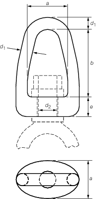
Figure 8.5.3 Bow piece for swivel
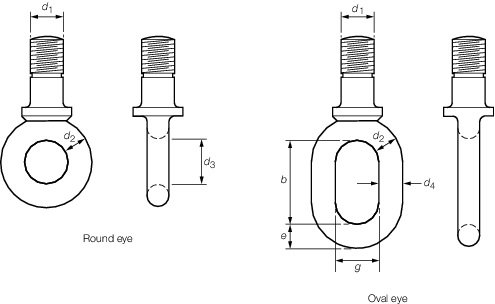
Figure 8.5.4 Round the oval eyes
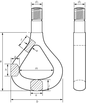
Figure 8.5.5 Triangular lifting eye
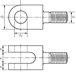
Figure 8.5.6 Lug fitting
5.3.6 Items whose
dimensions differ from those given in Table 8.5.4 Dimensions of higher tensile steel
‘C’ hooks may be designed in accordance with the requirements
given in Table 8.5.12 Swivels and eyes and Table 8.5.14 Form factors, K
.
Table 8.5.12 Swivels and eyes
| Item
|
Safe working load, in tonnes
|
| Swivel bow piece
|
|
| where
b < 2,55d
1, this value is to be multiplied
|
by 0,22 
|
| Round eye
|
|
| where
d
3 < 2,55d
2, this value is to be multiplied
|
by 0,22 
|
| Oval eye
|
|
| where
b < 2,55d
4, this value is to be multiplied
|
by 0,22 
|
| Triangular eye
|
Top
|
0,0069e
f
|
| Side
|
|
| Bottom
|
|
| Lugs
|
0,0125b (d
3 – d
2)
|
| Shank
|
c
d
1
2
|
|
|
Table 8.5.13 Values of c for swivel and
eyes
| Item
|
c
|
| Mild steel
|
Higher tensile
steel
|
| Swivel bow piece
|
0,0066
|
0,0088
|
| Round eye
|
0,0176
|
0,0236
|
| Oval eye
|
0,0057
|
0,0076
|
| Shank
|
0,00493
|
0,00625
|
Note Higher tensile steel is defined as steel having a tensile
strength not less than 540 N/mm2.
|
Table 8.5.14 Form factors, K
| Shape of
section
|
|
|
K
|
| Square
|
H = B
|

|
1,00
|
| Circular
|
H = B
|

|
0,66
|
| Rectangular
|
H = 0,75B
|

|
0,95
|
|
H = 0,50B
|
0,90
|
Radius at intrados
and extrados
|
H = 0,90B
|

|
0,80
|
Radius at intrados
only
|
H = 0,70B
|

|
0,75
|
| Ellipse
|
H = 1,25B
|

|
0,66
|
|
H = 0,75B
|
0,65
|
|
H = 0,50B
|
0,64
|
| Semi-circle
|
H = 0,50B
|

|
0,64
|
Note Values for intermediate shapes may be obtained by
interpolation.
|
5.4 Chains, links and rings
5.4.1 The overall
dimensions of the links of chain are to be within the limits in Table 8.5.15 Link chain limits.
Table 8.5.15 Link chain limits
|
|
Length
|
Breadth
|
| Short link
|
4,5d –
5,0d
|
3,25d –
3,5d
|
| Long link
|
7,0d –
9,0d
|
3,25d –
3,5d
|
| Symbols
|
|
d =nominal diameter of the chain
|
5.4.2 The certified
safe working load of short or long link chain is not to exceed the
values derived from Table 8.5.16 Safe working load of chain.
Proposals for the use of alloy steel chains will be specially considered.
Table 8.5.16 Safe working load of chain
| Item and material
|
Safe working load, in
tonnes
|
| Short
link
|
|
|
|
Mild steel
|
0,0094d
2
|
|
|
Higher tensile
steel
|
0,0125d
2
|
|
|
ISO Grade 40
|
0,0161d
2
|
|
|
|
|
| Long
link
|
|
|
|
Mild steel
|
0,0063d
2
|
|
|
Higher tensile steel
|
0,00825d
2
|
Note
1. Where d is the nominal diameter
of the chain, in mm.
Note
2. ISO Grade 40 chain is to comply with
the requirements of ISO/R 1834, 1835 and 1836 as appropriate.
|
5.4.3 The safe working
load for links or rings is to be not greater than the value obtained
from Table 8.5.17 Safe working load of links and
rings.
Table 8.5.17 Safe working load of links and
rings
| Item
|
Safe working load, in
tonnes
|
| Swivel bow piece
|
|
| where b < 2,55d,
this value is to be multiplied
|
by 0,22 
|
| Rings
|
|
| where a < 2,55d,
this value is to be multiplied
|
by 0,22 
|
|
|
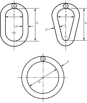
Figure 8.5.7 Chain link and ring
Table 8.5.18 Values of c for links and
rings
Minimum tensile
strength of
material, in N/mm2
|
Value
of c
|
| Links
|
Rings
|
| 430
|
0,0053
|
0,0116
|
| 540
|
0,0071
|
0,0155
|
5.5 Miscellaneous items
5.5.1 The triangle
plate for use with a span chain or with union purchase cargo runners
is to be provided with three holes of diameter not less than 1,25
times the diameter of the associated shackle pin. One of the holes
may be extended as a slot to facilitate reeving of the shackle.
5.5.2 The corners
of the plate are to be radiused. The corner radius, measured from
the centre of each hole is to be not less than the diameter of the
hole. The thickness of the plate is to be not less than one half the
width of the jaw of the associated shackle. The radius of the corners
and thickness of the plate are to be such that, when subjected to
the safe working load, the mean tensile stress in the material around
the hole does not exceed (25 + SWL) N/mm2, where the SWL
is measured in tonnes.
5.5.4 Tubular bodies
and end fittings of rigging screws are to be of steel having a tensile
strength not less than 350 N/mm2. The tensile stress in
the body and in the shanks of the end fittings is not to exceed (25
+ SWL) N/mm2, where SWL is the safe working load, in tonnes,
of the rigging screw.
|