
Section
3 Blocks
3.1 General
3.1.1 A typical
cargo block is shown diagrammatically in Figure 8.3.1 Typical cargo block with the component items labelled for reference.

Figure 8.3.1 Typical cargo block
3.1.2 The ultimate
strength of the block as an assembled unit is in no case to be less
than five times the resultant load for which the block is designed.
For blocks that are used in situations where the hoisting factor, F
h, for the lifting appliance is greater than 1,6,
a block of larger nominal capacity is to be used such that the normal
test load meets the requirements of Note 4 in Table 12.1.1 Proof loads for loose gear.
3.1.3 The safe working
load of each block is to be appropriate to its particular position
in the rig and is to be not less than the resultant load determined
in accordance with the appropriate Chapter of this Code. Blocks are
not to be used in positions other than those for which they were approved
without first confirming that their safe working load is at least
that required for the proposed location.
3.1.4 The required
safe working load of the block is to be determined by reference to
the resultant load, R, imposed on the block at its particular
position in the rig.
3.1.5 The safe working
load of a single sheave block is assessed on one particular condition
of loading, namely where the block is suspended by its head fitting
and where the cargo load is attached to a wire passing around the
sheave such that the hauling part is parallel to the part to which
the load is attached, see
Figure 8.3.2 Safe working load of single sheave
blocks. The SWL marked on the block is the weight, W in tonnes,
that can safely be lifted by the block, when rigged in this way. The
resultant load, R, on the head fitting (neglecting friction)
is, however, twice the SWL marked on the block, i.e. 2W tonnes.
The block and head fitting must, therefore, be designed to take a
resultant force of 2W tonnes and the proof-load applied
to the head fitting must be based on this resultant force. That is,
the proof-load will be 4W tonnes.
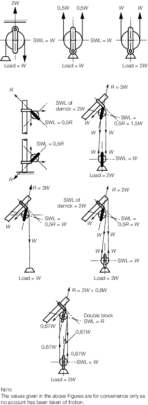
Figure 8.3.2 Safe working load of single sheave
blocks
3.1.6 When the same
block is rigged as a lower cargo block (the load being attached to
the head fitting), the SWL marked on the block is unchanged, but the
resultant force on the head fitting is only W tonnes.
As the block has been designed to withstand a resultant load on the
head fitting of 2W tonnes, the block is safe to support
a cargo load of 2W tonnes.
3.1.7 For single
sheave blocks with beckets, the SWL marked on the block is to be not
less than one half the resultant load on the head fitting.
3.1.8
Figure 8.3.2 Safe working load of single sheave
blocks gives examples of the use of
single sheave blocks and the method of obtaining their SWLs. In all
cases with single sheave blocks, the shackle or link securing the
block is to be marked with an SWL which is twice the SWL marked on
the block.
3.1.9 The safe working
load marked on any multiple sheave block is to correspond to the maximum
resultant load on the head fitting of that block.
3.2 Design loads and stresses
3.2.1 The percentage
of the resultant load on the head fitting which is transmitted by
a sheave is to be taken as not less than the value given in Table 8.3.1 Percentage load transmitted by a
sheave
Table 8.3.1 Percentage load transmitted by a
sheave
| Type of block
|
Number of sheaves
|
Bushed or plain bearings
|
Roller or ball bearings
|
| Without becket
|
With
becket
|
Without
becket
|
With becket
|
| Double
|
2
|
52
|
43
|
51
|
42
|
| Treble
|
3
|
37
|
32
|
35
|
30
|
| Fourfold
|
4
|
29
|
26
|
27
|
24
|
| Fivefold
|
5
|
24
|
22
|
22
|
20
|
| Sixfold
|
6
|
21
|
20
|
19
|
18
|
| Sevenfold
|
7
|
19
|
18
|
17
|
16
|
| Eightfold
|
8
|
17
|
16
|
15
|
14
|
Note Friction allowance taken as 5% for bushed or plain
bearings and 2% for roller or ball bearings.
|
3.2.2 The percentage
of the resultant load on the head fitting which is transmitted to
the side straps and partition plates of the sheave is to be taken
as not less than the value given in Table 8.3.2 Percentage load on side plates or
supporting straps
Table 8.3.2 Percentage load on side plates or
supporting straps
| Type of block
|
Number of sheaves
|
Number of supports
|
Bushed or plain bearings
|
Roller or ball bearings
|
| Inner
|
Outer
|
Partition
|
Side strap
|
Partition
|
Side
strap
|
| Double
|
2
|
1
|
2
|
63
|
20
|
63
|
19
|
| Treble
|
3
|
2
|
2
|
40
|
15
|
38
|
14
|
| Fourfold
|
4
|
3
|
2
|
32
|
12
|
30
|
11
|
| Fivefold
|
5
|
4
|
2
|
26
|
10
|
24
|
9
|
| Sixfold
|
6
|
5
|
2
|
23
|
9
|
21
|
8
|
| Sevenfold
|
7
|
6
|
2
|
21
|
8
|
18
|
7
|
| Eightfold
|
8
|
7
|
2
|
19
|
7
|
16
|
6
|
Note
1. Friction allowance taken as 5% for
bushed or plain bearings and 2% for roller or ball bearings.
Note
2. Where a becket is fitted, the
partitions and straps are to be designed to take account of the loads
imposed on the block.
|
3.2.3 The load on
a becket, where fitted, is to be taken as the maximum load to which
it may be subjected in service.
3.2.4 The stresses
in the component parts of the block are to be determined from the
unfactored loads transmitted from the sheaves and straps and are not
to exceed the values given in Table 8.3.3 Allowable stresses in
blocks
Table 8.3.3 Allowable stresses in
blocks
| Item
|
Allowable stress
|
| Sheave bush to axle
pin
|
Bearing pressure:
|
|
|
|
Single sheave 39
N/mm2
|
|
|
|
Multiple sheaves 31 N/mm2
|
|
|
|
|
| Axle pin to supporting straps and
partitions
|
Bearing
pressure:
|
|
|
|
154 N/mm2
|
|
|
|
|
| Axle pin and through bolts
|
Shear
stress:
|
|
|
|
Mild steel 62 N/mm2
|
|
|
|
Higher tensile steel 77
N/mm2
|
|
|
Bending
stress:
|
|
|
|
0,35σy N/mm2
|
|
|
|
|
| Becket to through bolt
|
Bearing
pressure:
|
|
|
|
39 N/mm2
|
|
|
|
|
| Straps and beckets,
|
Shear
pullout at end:
|
|
see
Figure 8.3.3 Dimensions of straps
|
|
54 N/mm2 on area 2 x
(a x t)
|
|
|
Tensile
stress at side:
|
|
|
|
Mild steel 77 N/mm2
|
|
|
|
Higher tensile steel 85
N/mm2
|
|
|
|
on area 2 x (b x t)
|
|
|
|
|
| Tensile stress in shanks
|
Mild
steel:
|
| of head fittings (based
|
|
R ≤ 50: σt = 62 N/mm2
|
| on core area)
|
|
50< R ≤ 75: σt =
(9,6R + 32) N/mm2
|
|
|
|
75 < R: σt = 77
N/mm2
|
|
|
Higher
tensile steel:
|
|
|
|
85 N/mm2
|
|
|
|
|
| Collars and nuts of shanks
|
Bearing
stress:
|
|
|
|
10 N/mm2
|
|
|
Minimum
diameter:
|
|
|
|
(1,5d + 3) mm
|
|
Note 1. Higher
tensile steel is defined as steel having a tensile strength not less than
540 N/mm2.
Note 2.
|
R |
= |
resultant load on the head fitting, in tonnes |
|
d |
= |
diameter of shank of head fitting, in mm. |
|
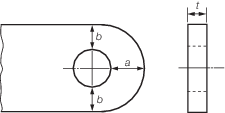
Figure 8.3.3 Dimensions of straps
3.3 Materials and construction
3.3.1 Sheaves may be forged or fabricated from steel plate. In general, castings
in steel or spheroidal graphite iron may be accepted, but grey cast iron or malleable
cast iron is not to be used for sheaves unless specially agreed.
3.3.2 Cast nylon
sheaves may also be used for general cargo handling applications when
the manufacturer indicates satisfactory service experience. However,
attention is drawn to the fact that whilst tests have indicated longer
service life for ropes used with cast nylon sheaves, the ropes do
not exhibit the normal warning signs of broken wires and may break
without external warning due to internal rope fatigue. Consequently,
it is recommended that one steel sheave be included in the reeving
arrangement, in addition to the steel winch drum.
3.3.3 The diameter
of the sheave is to be measured to the base of the rope groove and
is to be not less than what is given in Table 8.3.4 Diameter of sheaves for wire
rope
Table 8.3.4 Diameter of sheaves for wire
rope
| Rope use
|
Sheave diameter, in mm
|
| Running ropes
|
Fixed span ropes
|
| SOLAS LSA systems
|
12d
|
8d
|
Derrick systems
Vehicle
ramps
|
14d
|
10d
|
Cranes
Derrick cranes
Vehicle lifts
Cargo lifts
Mechanical lift docks
Diving systems
(excluding umbilicals)
Other lifting appliances
|
19d
|
10d
|
| Passenger lifts
|
39d
|
10d
|
Note
d is the diameter of the rope.
|
3.3.4 The depth
of the groove in the sheave is to be not less than three quarters
of the rope diameter. A depth equal to the rope diameter is recommended.
The contour at the bottom of the groove is to be circular over an
angle between 120° and 135° with the corresponding opening
angle to be between 60° and 45°. The radius of the groove
is to be as recommended by the rope manufacturer for the size and
application. The usual range of the radius of the groove is between
0,525d and 0,550d of the nominal rope diameter.
In no case shall the radius be smaller than 50 per cent of the actual
rope diameter.
3.3.5 Side and partition plates and straps are to be steel castings or fabricated
from steel plate. The plates are to project beyond the sheaves to provide ample
protection for the rope. Means are to be provided to prevent the rope from jamming
between the sheave and the side or partition plates by minimising the clearance or by
fitting suitable guards.
3.3.6 Snatch blocks
are to be well designed and arrangements are to be provided to ensure
that the block remains closed at all times when it is in use.
3.3.7 Crossheads and beckets may be steel cast, forged or machined from
plate.
3.3.8 Axle pins
are to be positively secured against rotation and lateral movement.
The surface finish of the pin is to be suitable for the type of bearing
to be used.
3.3.9 Provision
is to be made for lubricating all bearings and swivel head fittings
without dismantling the block and for withdrawing the axle pin for
inspection.
3.4 Blocks for fibre ropes
3.4.1 Blocks intended
for use with fibre ropes are not to be fitted with more than three
sheaves and a becket or with four sheaves and no becket.
3.4.2 The diameter
of the sheave measured to the base of the rope groove is generally
to be not less than five times the nominal diameter of the rope. The
depth of the groove is to be not less than one third the diameter
of the rope. The contour at the bottom of the groove is to be of a
radius in accordance with Ch 8, 3.3 Materials and construction 3.3.4 However,
for synthetic ropes, the manufacturer’s recommendations are
to be followed as this may vary with the type of construction and
material used.
3.4.3 Proposals
to use materials other than steel or iron castings for the sheaves
and body of the block will be considered. Bearing pressures and stresses
are to be appropriate to the materials used.
3.5 Hook blocks
3.5.1 Blocks that
are integrated with a hook are known as hook blocks. As an alternative
to the allowable stresses given in Table 8.3.3 Allowable stresses in
blocks, the hook blocks are to comply with all the requirements
below:
-
The hook blocks are to be designed with a safety factor against the
ultimate tensile strength as given below:
For hook blocks with SWL ≤ 25 t, SF = 5,0
and SWL ≥ 160 t, SF = 3,0.
For hook blocks with a SWL between 25 t and 160 t, the safety factor
should be based on the equation below:
where
|
SF
|
= |
minimum safety factor required
The minimum
safety factor (SF) shall be increased by the ratio of
Fh/1,6.
|
|
SWL |
= |
safe working load of hook block, in tonnes. |
The minimum safety factor (SF) shall be increased by the ratio
of Fh/1,6.
-
The hook block is to be designed by applying the hoist factor and duty
factor appropriate for the situation of operation and for the SWL of the hook and
using the allowable stress criteria given in Ch 4, 2.17 Allowable stress – Elastic failure, for cases 1 and 2.
-
The hook block is to be designed for the applicable test load for the
hook and using the allowable stress criteria given in Ch 4, 2.17 Allowable stress – Elastic failure, for case 3.
Large hook blocks, well in excess of 160 t SWL, will be specially
considered.
|
| Copyright 2022 Clasifications Register Group Limited, International Maritime Organization, International Labour Organization or Maritime
and Coastguard Agency. All rights reserved. Clasifications Register Group Limited, its affiliates and subsidiaries and their respective
officers, employees or agents are, individually and collectively, referred to in this clause as 'Clasifications Register'. Clasifications
Register assumes no responsibility and shall not be liable to any person for any loss, damage or expense caused by reliance
on the information or advice in this document or howsoever provided, unless that person has signed a contract with the relevant
Clasifications Register entity for the provision of this information or advice and in that case any responsibility or liability is
exclusively on the terms and conditions set out in that contract.
|
 |
|