
Section
2 Shipboard cranes
2.1 General
2.1.1 This Section
applies to shipboard cranes, generally described in Ch 4, 1.2 Lifting appliances and crane types 1.2.1, which are designed
to operate in a harbour or sheltered water conditions where there
is no significant movement of the ship due to wave action and the
significant wave height is not greater than 0,6 m.
2.1.2 The forces
and loads acting on the crane structure are to be determined in accordance
with the operating and environmental conditions for which the crane
is to be certified and must be clearly specified on all crane submissions,
together with the speeds of all crane movements, braking times, lifting
capacities, ranges, etc.
2.2 Load considerations
2.2.1 Consideration
is to be given to the utilisation and duty of the particular type
of crane or lifting appliance in the ‘inservice’ condition
with respect to the following forces and loads:
-
Dead loads.
-
Live loads.
-
Dynamic forces due to
the various crane movements.
-
Forces due to ship inclination.
-
Load swing caused by
non-vertical lift horizontal movement of the crane and load.
-
Wind forces and environmental
effects.
-
Loads on access ways,
platforms, etc.
-
Snow and ice when considered
relevant.
2.2.2 The crane
structure and any stowed arrangements are also to be examined with
respect to the stowage condition for the following criteria, as applicable:
-
Forces due to the ship
motion and inclination.
-
Wind and environmental
effects.
-
Snow and ice.
2.3 Duty factor
2.3.1 Cranes are
grouped depending on the nature of the duty they perform and each
group is designated a duty factor, as given in Table 4.2.1 Duty factor, F
d
.
Table 4.2.1 Duty factor, F
d
| Crane types and
use
|
Duty factor
|
Stores cranes
Maintenance cranes
Engine room
cranes
|
1,0
|
Deck jib
cranes
Container cranes
Gantry cranes
Floating cranes
|
1,05
|
| Grab cranes
|
1,20
|
| Other lifting appliances
|
Special
consideration
|
2.3.2 The duty factor, F
d, depends on the frequency of operation and the
severity of the load lifted with respect to the appropriate safe working
load of the crane concerned and is used to factor both the live and
dead load components of loading. The factor assumes normal marine
use, operating life not in excess of 6 x 10⁵ cycles and
that the crane or lifting appliance has been designed as per the principles
of a low susceptibility to fatigue. Consideration is to be given to
increasing these values where extra heavy duty is envisaged.
2.3.3 The reduction
of the duty factor below the minimum values as in Table 4.2.1 Duty factor, F
d
is only permitted if sufficient
evidence is provided that the load cycles and the severity of the
load spectrum are below the assumed normal marine use. Alternatively,
the duty factor may be calculated on the basis of a recognised National
or International Standard (e.g. F.E.M. 1.001) upon agreement with
LR.
2.3.4 Where appropriate,
fatigue calculations are to be carried out in accordance with a recognised
National Standard using load cycles and load spectrum agreed between
the manufacturer and the Owner.
2.4 Basic loads
2.4.1 The basic
loads applied to the crane comprise the dead load, L
g,
and the live load, L
l, which are as
defined in Ch 1 General.
2.5 Dynamic forces
2.5.1 The dynamic
forces due to hoisting are those imposed on the structure by shock
and accelerating the live load from rest to a steady hoisting speed.
To take this effect into account in the design, the live load is multiplied
by a hoisting factor, F
h.
2.5.2 The hoisting
factor is given by:
where
|
V
h
|
= |
hoisting speed, in m/s but need be taken as not greater than 1,0
m/s |
|
C
l
|
= |
a coefficient depending on the stiffness of the crane concerned |
|
C
l
|
= |
0,3 for jib type cranes, and 0,6 for gantry type cranes. |
|
|
= |
A value of F
h is to be taken as not less than 1,10 for jib cranes and 1,15 for
gantry cranes.
For grab duty, F
h is to be multiplied by 1,05. Values of F
h plotted against hoisting speed, V
h, are given in Figure 4.2.1 Values of hoisting factor,
F
h
. |
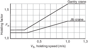
Figure 4.2.1 Values of hoisting factor,
F
h
2.6 Dynamic forces due to crane movements
2.6.1 Consideration
is to be given to the forces which occur when a crane travels along
a track or rails resulting in a vertical acceleration acting on the
crane and its load together with the horizontal acceleration due to
the crane changing speed whilst travelling.
2.6.2 The vertical
acceleration is usually small, provided the rail and joints are level
and smooth, and since it may be considered that it does not occur
at the same time as the maximum dynamic force due to hoisting, it
may generally be neglected.
2.6.3 The horizontal
acceleration including that due to braking is to be supplied by the
manufacturer. Where the acceleration is not available but speed and
working conditions are known, the acceleration is to be obtained from
the following formulae:
-
For cranes with low
travel speed (0,4–1,5 m/s)
-
For cranes with moderate
to high travel speed (1,5–4,0 m/s) and normal acceleration
-
For cranes with travel
speed (1,5–4,0 m/s) and high acceleration (0,4–0,7 m/s2)
where
|
a
t
|
= |
acceleration, in m/s2
|
|
V
t
|
= |
travel speed, in m/s. |
Where the speed is known but working conditions are
not, the highest value of acceleration for the appropriate speed is
to be used.
2.6.4 In cases where
the crane drive control system ensures that motions such as hoisting,
travelling or slewing cannot occur simultaneously and the loading
caused by one motion is practically zero when the other motion starts,
loadings due to hoisting, travelling motions or slewing do not need
to be superimposed.
With respect to the load combination formula as given in the
Code, this would result in:
| Case 1a:
|
F
h > 1,0 (Hoisting) –> L
h2(Travelling or slewing) = 0
|
| Case 1b:
|
F
h = 1,0 (Live load at rest) –> L
h2 (Travelling or slewing) > 0
|
| Case 2:
|
Similar.
|
where
|
L
h2
|
= |
the next most unfavourable horizontal load (usually due to travelling
or slewing acceleration). |
2.7 Slewing forces
2.7.1 The inertia
forces acting on the load and crane structure resulting from slewing
the crane are to be considered.
2.7.2 The slewing
acceleration or, alternatively, the slewing speed and braking time,
is to be supplied by the manufacturer. Where this is not available,
the acceleration at the jib head of the crane, with the crane jib
at maximum radius, is to be taken as 0,6 m/s2.
2.7.3 The slewing acceleration is to be applied to dead weight and the SWL of the
crane. The slewing acceleration is to be taken as 100 per cent of its nominal value up
to 40 t SWL and can then gradually be reduced to 50 per cent of its nominal value until
160 t SWL. Beyond 160 t SWL, the slewing acceleration shall remain constant at 50 per
cent of its nominal value. The SWL to determine the slewing acceleration is to be taken
as the maximum SWL on the load versus radius charts. The graphical representation of the
above can be found in Figure 4.2.2 Slewing acceleration.

Figure 4.2.2 Slewing acceleration
2.8 Centrifugal forces
2.8.1 In general,
the effect of centrifugal force acting on the crane structure is small
and may be neglected.
2.9 Transverse forces due to travel motions
2.9.1 Consideration
is to be given to racking loads which occur when two pairs of wheels
or bogies move along a set of rails and produce a couple formed by
horizontal forces normal to the rail direction.
2.9.2 The value
of the racking force, F
R, is calculated from
the following formulae:
where
|
F
W
|
= |
vertical load on wheel or bogie, in Newtons |
|
C
2
|
= |
coefficient dependent on wheel track, t, and base, b,
as follows: |
-
C
2 = 0,05 for values t/b ≤ 2,0
-
C
2 = 0,025 t/b for values 2,0 < t/b ≤ 8,0
-
C
2 =
0,20 for values t/b > 8,0
Figure 4.2.3 Equilibrium of forces due to crane
travelling along track gives the equilibrium
of forces applied to the crane. Alternative calculation methods as
detailed in recognised National or International Standards (e.g. F.E.M.
1.001, Booklet 9) may be considered.
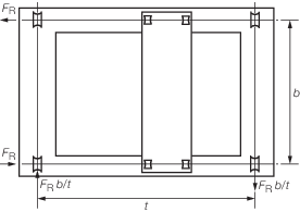
Figure 4.2.3 Equilibrium of forces due to crane
travelling along track
2.10 Buffer forces
2.10.1 Forces applied
to the crane structure as a result of the crane coming into contact
with buffers are to be considered. Where decelerating devices are
fitted which operate before the crane reaches the end of the track,
and providing such devices operate automatically and give effective
deceleration to the crane at all times, the reduced speed produced
by these devices may be used in the calculations.
2.10.2 For cranes
where the load is free to swing, the forces are to be calculated equating
the energy capacity of the buffer with the kinetic energy of the crane
dead weight, i.e. excluding the live load, when the crane is travelling
at 0,7 times its design speed.
2.10.3 For cranes
where the load is restricted from swinging by rigid guides, the same
method is to be used to calculate the forces but the dead weight plus
live load is to be used in the calculation.
2.11 Forces due to ship motion
2.11.1 Shipboard
cranes are to be designed to operate safely and efficiently in a harbour
or sheltered water environment at an angle of heel of 5° and angle
of trim of 2° occurring simultaneously.
2.11.2 Special
consideration may be given where it is intended to operate a crane
on a vessel at an angle of heel differing from 5° or an angle
of trim differing from 2°. Where angles less than these are proposed,
evidence is to be provided to demonstrate that such lesser angles
cannot be exceeded in service.
2.11.3 In the stowed
condition, the crane, its stowage arrangements and the structure in
way are to be designed to withstand forces resulting from the following
two design combinations:
-
- Acceleration normal to deck of ±1,0g.
- Acceleration parallel to deck in fore and aft direction of
±0,5g.
- Static heel of 30°.
- Wind of 63 m/s acting in fore and aft direction.
-
- Acceleration normal to deck of
±1,0g.
- Acceleration parallel to deck in transverse direction of
±0,5g.
- Static heel of 30°.
- Wind of 63 m/s acting in a transverse direction.
2.11.4 Alternatively,
where the crane is to be fitted to a conventional ship and the ship’s
characteristics are known, the forces may be calculated using accelerations
obtained from consideration of the ship’s motions given in Table 4.2.2 Ship motions, together with the force due
to a wind speed of 63 m/s acting in the most unfavourable direction.
2.11.5 The forces
due to ship motions are to be determined in accordance with Table 4.2.3 Forces due to ship motions.
Table 4.2.3 Forces due to ship motions
| Source
|
Component of force, in Newtons
|
| Normal to deck
|
Parallel to deck
|
| Transverse
|
Longitudinal
|
| STATIC
|
|
|
|
|
|
Roll
|
W cos φ
|
W sin φ
|
|
|
|
Pitch
|
W cos ψ
|
|
W sin ψ
|
|
|
Combined
|
W cos (0,71φ) cos (0,71ψ)
|
W sin (0,71φ)
|
W sin (0,71ψ)
|
| DYNAMIC
|
|
|
|
|
|
Roll
|
0,07024 W
 y
y
|
0,07024 W
 z
r
z
r
|
|
|
|
Pitch
|
0,07024 W
 x
x
|
|
0,07024
W
 z
p
z
p
|
|
|
Heave:
|
|
|
|
|
|
Roll
|
0,05
W
 cos φ cos φ
|
0,05
W
 sin φ sin φ
|
|
|
|
Pitch
|
0,05
W
 cos ψ cos ψ
|
|
0,05
W
 sin ψ sin ψ
|
|
|
Combined
|
0,05
W
 cos(0,71φ) cos(0,71ψ) cos(0,71φ) cos(0,71ψ)
|
0,05
W
 sin(0,71φ) sin(0,71φ)
|
0,05
W
 sin(0,71ψ) sin(0,71ψ)
|
| Symbols
|
| y
= transverse parallel to deck from centreline of ship to centreline of
crane, in metres
|
| x
= longitudinal distance parallel to deck from centre of pitching motion,
taken to be at longitudinal centre of flotation, to centreline of crane, in
metres
|
| zr = distance normal to deck from centre of rolling
motion, taken to be at the vertical centre of gravity of the ship, to the
vertical centre of gravity of the crane, in metres
|
| zp = distance normal to deck from centre of pitching
motion to centre of gravity of crane, in metres
|
| W
= weight of crane or its component part, in Newtons
|
| φ and ψ
are in degrees
|
2.11.6 The following
combinations of static and dynamic forces are to be considered:
- Rolling motion only:
- Static roll + dynamic roll + dynamic heave (at roll angle
φ).
- Pitching motion only:
- Static pitch + dynamic pitch + dynamic heave (at pitch angle ψ).
- Combined motion:
- Static combined + 0,8 (dynamic roll + dynamic pitch) + dynamic
heave combined.
In each case, the component of force due to wind is to be included
where applicable.
2.11.7 Proposals
to use other values are to be substantiated by calculations and will
be subject to special consideration.
2.12 Wind loading
2.12.1 The wind
pressure, p, acting on the structure is given by the
following formula:
where
The wind speed for the operating condition is to
be taken as 20 m/s and for the stowed condition as 63 m/s.
2.12.2 Where it
is anticipated that wind speeds in excess of those defined in Ch 4, 2.12 Wind loading 2.12.1 may occur, these higher wind speeds
are to be considered.
2.12.3 The wind
force acting on the suspended load is to be taken as 300 N per tonne
of SWL, but where a crane is to be designed to handle loads of a specific
shape and size the wind force is to be calculated for the appropriate
dimensions and configuration.
2.12.4 The wind
force on the crane structure or individual members of the structure
is to be calculated from the following expression:
where
|
A
|
= |
the effective area of the structure concerned, i.e. the solid area
projected onto a plane perpendicular to the wind direction, in m2
|
|
p
|
= |
wind pressure, in N/m2
|
|
Cf
|
= |
force coefficient in the direction of the wind |
|
Fw
|
= |
force due to the wind, in Newtons. |
2.12.5 The force
coefficient for various structural components is given in Table 4.2.4 Force coefficient (C
f) . The values for individual
members vary according to the aerodynamic slenderness and, in the
case of large box sections, with the section ratio. The aerodynamic
slenderness and section ratio are given in Figure 4.2.4 Aerodynamic slenderness and
section ratio.
Table 4.2.4 Force coefficient (C
f)
| Type
|
Description
|
Aerodynamic slenderness l/b or l/D
|
| ≤5
|
10
|
20
|
30
|
40
|
≥50
|
Individual
members
|
Rolled
sections, rectangles, hollow sections, flat plates,
box
sections with b or d less than 0,5 m
|
1,30
|
1,35
|
1,60
|
1,65
|
1,70
|
1,80
|
| Circular sections, where
|
D
V
s < 6 m2/s
|
|
0,60
|
0,70
|
0,80
|
0,85
|
0,90
|
0,90
|
|
|
D
V
s ≥ 6 m2/s
|
|
0,60
|
0,65
|
0,70
|
0,70
|
0,75
|
0,80
|
| Box sections with b or d greater than 0,5 m
|
b/d
|
|
|
|
|
|
|
| ≥ 2,00
|
1,55
|
1,75
|
1,95
|
2,10
|
2,20
|
|
| 1,00
|
1,40
|
1,55
|
1,75
|
1,85
|
1,90
|
|
| 0,50
|
1,00
|
1,20
|
1,30
|
1,35
|
1,40
|
|
| 0,25
|
0,80
|
0,90
|
0,90
|
1,00
|
1,00
|
|
Single lattice
frames
|
Flat-sided sections
|
1,70
|
| Circular sections, where
|
D
V
s < 6 m2/s
|
|
1,10
|
|
|
D
V
s ≥ 6 m2/s
|
|
0,80
|
Machinery
houses,
etc.
|
Rectangular clad structures on ground or solid base (air flow beneath
structure prevented)
|
1,10
|

Figure 4.2.4 Aerodynamic slenderness and
section ratio
2.12.6 Where a
structure consists of a framework of members such that shielding takes
place, the wind force on the windward frame or member and on the sheltered
parts of those behind it are calculated using the appropriate force
coefficient. The force coefficient on the sheltered parts are to be
multiplied by a shielding factor η. The values of η vary
with the solidity and spacing ratio of the framework. Values of η
are given in Table 4.2.5 Shielding factor (η) for the
solidity and spacing ratio as defined in Figure 4.2.5 Solidity ratio and spacing
ratio.
Table 4.2.5 Shielding factor (η)
| Spacing ratio
a/b
|
Solidity ratio A/A
e
|
| 0,1
|
0,2
|
0,3
|
0,4
|
0,5
|
≥ 0,6
|
| 0,5
|
0,75
|
0,4
|
0,32
|
0,21
|
0,15
|
0,1
|
| 1,0
|
0,92
|
0,75
|
0,59
|
0,43
|
0,25
|
0,1
|
| 2,0
|
0,95
|
0,8
|
0,63
|
0,5
|
0,33
|
0,2
|
| 4,0
|
1
|
0,88
|
0,75
|
0,66
|
0,55
|
0,45
|
| 5,0
|
1
|
0,95
|
0,88
|
0,81
|
0,75
|
0,68
|
| 6,0
|
1
|
1
|
1
|
1
|
1
|
1
|
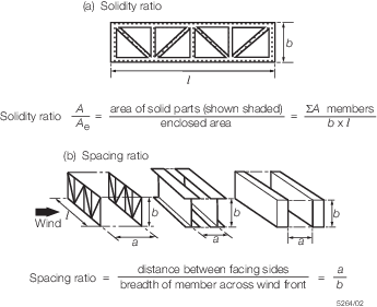
Figure 4.2.5 Solidity ratio and spacing
ratio
2.12.7 Where a structure consists of a number of identical frames or members spaced
equidistantly behind each other in such a way that each frame shields those behind it,
the wind load is to be obtained from the following expression:
|
F
|
= |
A
p
C
f

|
where
|
η |
= |
shielding factor from Table 4.2.5 Shielding factor (η), but ηn is to be taken as not
less than 0,1 |
|
n |
= |
number of frames, but to be taken as not greater than 9. |
2.12.8 For latticed tower structures, the ‘face on’ wind force based on the solid
area of the windward face is to be multiplied by the following coefficients:
-
For towers composed of flat-sided sections:
1,7p (1 + η)
-
For towers composed of circular sections:
where D
V
s < 6,0 m2/s:
1,1 p (1 + η)
and D
V
s ≥ 6,0 m2/s:
1,4 p (1 + η)
where
|
D
|
= |
the diameter of the section, in metres |
|
Vs
|
= |
the design wind speed, in m/s |
2.12.9 The maximum
wind load on a square section tower occurs when the wind blows onto
a corner and is to be taken as 1,2 times the ‘face on’
load.
2.12.10 Alternative
proposals to calculate the wind load will be considered.
2.13 Snow and ice loads
2.13.1 In general,
the effects of snow and ice loads acting on the crane structure may
be neglected, although they are considered where a particular design
or application indicates that these loads are significant.
2.14 Temperature effects
2.14.1 In general,
temperature effects need only be considered with respect to the selection
of the steels used in the construction of the crane, see
Ch 4, 2.25 Materials.
2.15 Load combinations
2.15.1 The crane
design is to be considered with respect to loads resulting from the
following conditions:
|
Case 1
|
Crane operating without wind.
|
|
Case 2
|
Crane operating with wind.
|
|
Case 3
|
Crane in stowed condition.
|
|
Case 4
|
Crane subjected to exceptional
loading.
|
2.15.2
Case 1. For the condition of the crane operating without wind, the design is to
be considered with respect to a combination of dead load, live load and horizontal
forces defined in Ch 4, 2.6 Dynamic forces due to crane movements to Ch 4, 2.11 Forces due to ship motion, as given by the following
expression:
- F
d [L
g + F
h (L
l + L
h1) + L
h2 + L
h3]
- where
|
F
d
|
= |
duty factor |
|
L
g
|
= |
dead load |
|
F
h
|
= |
hoisting factor |
|
L
l
|
= |
live load |
|
L
h1
|
= |
the horizontal component of live load due to heel and trim |
|
L
h2
|
= |
the next most unfavourable horizontal load (usually due to slewing
acceleration) |
|
L
h3
|
= |
the horizontal component of dead load due to heel and trim. |
2.15.3
Case 2. For the condition of the crane operating with wind, the design is to be
considered with respect to a combination of dead load, live load and horizontal forces
defined in Ch 4, 2.6 Dynamic forces due to crane movements to Ch 4, 2.11 Forces due to ship motion, together with the most
unfavourable wind load. This is given by the following expression:
- F
d [L
g + F
h (L
1 + L
h1) + L
h2 + L
h3] + L
w
- where
|
L
w
|
= |
the most unfavourable wind load. |
2.15.4
Case 3. The crane is to be considered in its stowed condition when subjected to
forces resulting from accelerations due to the ship’s motions and static inclination,
together with wind forces appropriate to the stowed condition. (see
Ch 4, 2.11 Forces due to ship motion) The effects of anchorages,
locks and lashings, etc. are to be taken into consideration.
2.15.5
Case
4. The crane may also need to be considered with respect to
the following exceptional load conditions:
- Coming into contact with buffers.
- Failure of the hoisting rope during testing or normal operation
(Fh, to be taken as –0,3).
- Sudden release of load during testing or normal operation (Fh, to
be taken as –0,3).
- Test loading.
For heavy lift cranes (or lifting appliances) a risk assessment is to be
carried out to evaluate the consequences due to failure of the hoisting rope or sudden
release of load and the identified risks are to be mitigated to acceptable levels. The
system integrator in cooperation with the manufacturer of the crane and the designer of
vessel shall prepare a Safety Statement in line with LR’s ShipRight Procedure Risk
Based Certification (RBC) process and/or in line with the requirements of the
National Administration (as applicable).
The risk mitigation may include the following measures;
- the application of a testing concept that would identify components along the
main load path which could be tested separately before assembly of the lifting
appliance on board, where the extent of the separate testing is also to be based
on the results of the risk assessment;
- positioning of the load to be lifted or test load (e.g. at the stern of the ship)
in such a way that any single point failure (e.g. drop of load) will not lead to
further failures (e.g. collapse of parts of the crane); and
- consideration of the design of the ship and lifting appliance as a single system
in such a way that any single point failure will not lead to further failures
(e.g. capsizing of the ship, damage of the crane, possible interference with any
onboard structure).
2.16 Stability
2.16.1 Travelling
cranes, trolleys, grabs, etc. which are capable of travelling whilst
loaded are to be examined with regard to stability against overturning
for the following conditions:
-
The worst operating
condition as given by load combination Case 2, including forces resulting
from an acceleration at deck level of 0,67 m/s2 or maximum
acceleration, if known.
-
Consideration of sudden release of load in accordance with load
combination Case 2, with the hoisting factor, Fh, taken as
–0,3.
2.16.2 The overturning
moment is to be not greater than 80 per cent of the stabilising moment.
2.16.3 Travelling
cranes, etc. are to be provided with stowage locks or lashings or
other means of resisting forces resulting from consideration of load
combination Case 3.
2.16.4 Devices
used for anchoring the crane or trolley to its track or rails may
be taken into account in calculating the stability of travelling cranes
only if:
-
Such cranes or trolleys
do not travel when loaded.
-
The design of the rail
and its anchoring devices are such that stability is achieved by use
of efficient wheels and properly designed rails. Alternative devices
will be considered.
2.16.5 Consideration
is to be given to the following aspects of crane stability:
-
Travelling cranes are
to be provided with efficient stops at both limits of travel and are
to be designed such that the crane will remain stable after contact
with the stops under the most severe operating conditions.
-
Travelling cranes are
to be designed to prevent complete derailment or loss of stability
in the event of a wheel or axle failure or sudden release of load.
2.16.6 Jib cranes
are to be designed such that the jib does not ‘jack-knife’
under operational and test loads. Alternatively, suitable stops may
be fitted to prevent the jib from ‘jack-knifing’. Jack-knifing
is to be considered using the following expression:
- L
l + L
g + L
h1 + L
h3 + 1,2L
w
The components of the above expression are defined
in Ch 4, 2.15 Load combinations 2.15.2.
2.17 Allowable stress – Elastic failure
2.17.1 The allowable stress, σa, is to be taken as the failure stress of
the component concerned multiplied by a stress factor, F, which depends on the
load case considered. The allowable stress is given by the general expression:
where
Table 4.2.6 Stress factor, F
| Load case
|
Stress factor, F
|
| 1
|
0,67
|
| 2
|
0,75
|
| 3 and 4
|
0,85
|
2.17.2 The stress factors, F, for steels in which
σy/σu ≤ 0,85
where
|
σy
|
= |
minimum specified yield stress of material |
|
σu
|
= |
minimum specified ultimate tensile stress of the material |
|
|
= |
are given in Table 4.2.6 Stress factor, F
|
2.17.3 For steel with 0,85 < σy/σu ≤ 0,94, the allowable
stress is to be derived from the following expression:
|
σa
|
= |
0,459F (σu + σy) |
|
τa
|
= |
0,266F (σu + σy) |
where
2.17.4 Steel with σy/σu > 0,94 will be specially
considered.
2.17.6 The failure stresses for the elastic modes of failure are given in Table 4.2.7 Failure stress.
Table 4.2.7 Failure stress
| Mode of
failure
|
Symbol
|
Failure stress
|
| Tension
|
σt
|
1,0σy
|
| Compression
|
σc
|
1,0σy
|
| Shear
|
τ
|
0,58σy
|
| Bearing
|
σbr
|
1,0σy
|
2.17.7 For components subjected to combined stresses the following allowable
stress criteria are to be used:
-
σxx ≤ σa
-
σyy ≤ σa
-
τo ≤ τa
-
σe =  ≤ 1,1σa ≤ 1,1σa
where
|
σxx
|
= |
applied stress in x direction |
|
σyy
|
= |
applied stress in y direction |
|
τo
|
= |
applied shear stress |
|
σe |
= |
von Mises equivalent stress |
2.17.8 The allowable bearing stress for rotatable and fitted pin connections are to
be taken as per the allowable bearing stresses for fitted bolts given in Table 4.2.14 Allowable stresses for fitted
bolts. The allowable bearing stress for rotatable
pin connections with dynamics or loose fit will be specially considered.
Ball and roller bearings are to be in accordance with a recognised
National or International Standard.
The allowable bearing stress for
other surface-to-surface contact (pressures) is to be taken as in Ch 4, 2.17 Allowable stress – Elastic failure in
combination with Table 4.2.7 Failure stress.
2.17.9 In the case where the structural analysis is carried out by means of
detailed finite element models, higher allowable stresses may be applied as follows:
-
σ1.FE≤ 1,1σa
-
σ2.FE≤ 1,1σa
-
τo.FE≤ 1,1τa
-
σe.FE≤ 1,12σa
where
|
σ1.FE
|
= |
first principal stress |
|
σ2.FE
|
= |
second principal stress |
|
σe.FE
|
= |
von Mises equivalent stress |
Higher allowable stresses, as defined here, may only be applied if the
actual stresses are localised. In the case where the actual stresses may also be
calculated by means of analytical methods, these higher allowable stresses are not
applicable and Ch 4, 2.17 Allowable stress – Elastic failure 2.17.1 is to be applied.
2.18 Allowable stress – Compression, torsional and bending members
2.18.1 The allowable
stress for compression members is to be taken as the critical compressive
stress, σcr, multiplied by the allowable stress factor, F, as defined in Table 4.2.6 Stress factor, F
.
In addition to local failure due to the critical compression stress
being exceeded, consideration is to be given to the overall ability
of crane jibs to resist compression loading, see
Ch 4, 2.19 Crane jibs – Overall stability.
2.18.2 For members
subjected to simple compression, the critical compression stress is
given by the Perry-Robertson formulae as follows:
where
|
σe |
= |

|
|
η |
= |
0,001a

|
|
r
|
= |
radius
of gyration of member |
Alternative methods to calculate the simple critical compression stress as
per recognised National or International Standards or analysis taking into account
second and higher order effects may be considered. In the case where the stability is
calculated by means of second or higher order analysis, suitable imperfections are to be
taken into account and the loads are to be multiplied by the inverse of the stress
factor 1/F where the actual stress results are then to be compared with the yield
stress of the component.
Table 4.2.8 Value K, for different
constraint conditions
Table 4.2.9 Values of Robertson’s constant,
a, for various sections
| Type of
section
|
Thickness
of flange
or plate, in mm
|
Axis of
buckling
|
a
|
| Rolled I
section (universal beams)
|
|
xx
|
2,0
|
|
|
|
yy
|
3,5
|
|
|
|
|
|
| Rolled H
section (universal beams)
|
≤ 40
|
xx
|
3,5
|
|
See Note 1
|
|
yy
|
5,5
|
|
|
> 40
|
xx
|
5,5
|
|
|
|
yy
|
8,0
|
|
|
|
|
|
| Welded
plate I or H sections
|
≤ 40
|
xx
|
3,5
|
|
See Notes 1, 2 or 3
|
|
yy
|
5,5
|
|
|
> 40
|
xx
|
3,5
|
|
|
|
yy
|
8,0
|
|
|
|
|
|
| Rolled I or
H section with welded flange cover plates
|
|
xx
|
3,5
|
|
See Notes 1 and 4
|
|
yy
|
|
|
|
|
xx
|
2,0
|
|
|
|
yy
|
|
|
|
|
|
|
| Welded box
sections
|
≤ 40
|
any
|
3,5
|
|
See Notes 1, 3 and 4
|
> 40
|
any
|
5,5
|
|
|
|
|
|
| Rolled
channel sections, rolled angle sections or T-bars
|
|
any
|
5,5
|
| (rolled or
cut from universal beam or column)
|
|
|
|
|
|
|
|
|
| Hot-rolled
structural hollow sections
|
|
any
|
2,0
|
|
|
|
|
|
| Rounds,
square and flat bars
|
≤ 40
|
any
|
3,5
|
|
See Note 1
|
> 40
|
any
|
5,5
|
|
|
|
|
|
Compound
rolled sections (2 or more I, H or channel sections,
I
section plus channel, etc.)
|
|
any
|
5,5
|
|
|
|
|
|
| Two rolled
angle, channel or T-sections, back-to-back
|
|
any
|
5,5
|
|
|
|
|
|
| Two rolled
sections laced or battened
|
|
any
|
5,5
|
|
|
|
|
|
| Lattice
strut
|
|
any
|
2,0
|
Note
1. For thicknesses between 40 mm and 50
mm, the value of σcr may be taken as the average of the
value for thicknesses less than 40 mm and the value for thicknesses
greater than 40 mm.
Note
2. For welded plate I or H sections where
it can be guaranteed that the edges of the flanges will only be
flame-cut, a = 3,5 may be used for buckling about the y-y axis
for flanges up to 40 mm thick and a = 5,5 for flanges over 40
mm thick.
Note
3. Yield strength for sections fabricated
from plate by welding reduced by 25 N/mm2.
Note
4. ‘Welded box sections’ includes those
fabricated from four plates, two angles or an I or H section and two
plates but not box sections composed of two channels or plates with
welded longitudinal stiffeners.
|
2.18.4 For members
subjected to combined bending and compression, the following stress
criteria are to be used:
where
|
σb
|
= |
applied
bending stress |
|
σc
|
= |
applied
compression stress. |
2.18.5 The effects
of ‘lateral torsional buckling’, if applicable to the
specific design, are to be taken into consideration by using the methods
of recognised National or International Standards, as appropriate.
2.19 Crane jibs – Overall stability
2.19.1 In addition
to individual members of the jib structure being examined with respect
to buckling, crane jibs are to be considered with respect to critical
compressive failure of the jib as a whole with regard to both plan
and elevation planes.
2.19.2 The slenderness
ratio is the effective length of the jib divided by the radius of
gyration in the plane concerned. To allow for the variation in radius
of gyration with length, an effective radius of gyration is to be
calculated in accordance with Ch 4, 2.20 Slenderness ratio.
2.19.3 The effective
length of the jib is dependent on the constraint conditions at its
ends. The conditions are different in plan view from those in elevation
and are also dependent on the type of jib concerned, of which there
are two types, rope supported and cantilever jibs.
2.19.4 For rope
supported jibs, the effective length is to be calculated in the following
manner:
-
In elevation, the jib
can be considered as being fixed against translation and free to rotate
so that the effective length is taken as the actual length of the
jib for all jib attitudes, i.e. K = 1,0
-
In plan, the lower
end of the jib is to be considered as fixed against translation and
rotation by the jib pivots and the head is to be considered as partially
constrained with respect to translation by the hoist and luffing ropes,
the constraint varying with the tension in these ropes and attitude
of the jib. The effective length in plan view is given by
where
|
l |
= |
effective length |
|
L
|
= |
the actual length of the jib |
|
K
|
= |
a constant equal to 
|
|
C
|
= |
is the ratio of load applied to the jib head by the luffing
rope to that applied to the non vertical part of the hoist rope, and
R, R
H, R
S, D and H are dimensions, in mm, as shown in Figure 4.2.6 Geometry for jib stability
calculations. |

Figure 4.2.6 Geometry for jib stability
calculations
2.19.5 The above
method is considered satisfactory for conventional jibs. Alternatively,
and especially for jibs of slender or very high strength steel designs,
the construction is to be analysed taking into account second and
higher order effects due to deflection of the structure by iterative
or other suitable methods, and calculations submitted. In the case
where the stability is calculated by means of second or higher order
analysis, suitable imperfections are to be taken into account and
the loads are to be multiplied by the inverse of the stress factor
1/F, where the actual stress results are then to be compared
with the yield stress of the component.
2.20 Slenderness ratio
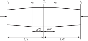
2.20.1 The slenderness ratio of compression members is given by the general
expression, i.e.  . For members which have constant area and uniformly varying second
moment of area and hence radius of gyration, such as crane jibs, an effective radius of
gyration is to be considered. The effective radius of gyration is given by: . For members which have constant area and uniformly varying second
moment of area and hence radius of gyration, such as crane jibs, an effective radius of
gyration is to be considered. The effective radius of gyration is given by:
where
Table 4.2.10
m factor for various values of I1
/I2
 / /
|
0
|
0,1
|
0,2
|
0,3
|
0,4
|
0,5
|
0,6
|
0,7
|
0,8
|
0,9
|
1,0
|
|
m
|
0,294
|
0,372
|
0,474
|
0,559
|
0,634
|
0,704
|
0,769
|
0,831
|
0,889
|
0,946
|
1,0
|

|
Table 4.2.11
m factor for various values of
I1/I2 and a/L
 / /
|
a/L
|
| 0,0
|
0,1
|
0,2
|
0,3
|
0,4
|
0,5
|
| 0,1
|
0,555
|
0,622
|
0,689
|
0,756
|
0,823
|
0,891
|
| 0,2
|
0,652
|
0,708
|
0,765
|
0,821
|
0,877
|
0,934
|
| 0,4
|
0,776
|
0,815
|
0,854
|
0,894
|
0,933
|
0,972
|
| 0,6
|
0,866
|
0,890
|
0,915
|
0,940
|
0,964
|
0,988
|
| 0,8
|
0,938
|
0,950
|
0,961
|
0,973
|
0,985
|
0,996
|
| 1,0
|
1,0
|
1,0
|
1,0
|
1,0
|
1,0
|
1,0
|
|
Table 4.2.12
m factor for various values of
I1/I2 and a/L
 / /
|
a/L
|
| 0,0
|
0,1
|
0,2
|
0,3
|
0,4
|
0,5
|
| 0,1
|
0,372
|
0,373
|
0,418
|
0,479
|
0,563
|
0,671
|
| 0,2
|
0,474
|
0,500
|
0,532
|
0,586
|
0,660
|
0,756
|
| 0,4
|
0,634
|
0,667
|
0,691
|
0,729
|
0,783
|
0,852
|
| 0,6
|
0,769
|
0,795
|
0,810
|
0,836
|
0,869
|
0,913
|
| 0,8
|
0,889
|
0,950
|
0,961
|
0,973
|
0,985
|
0,996
|
| 1,0
|
1,0
|
1,0
|
1,0
|
1,0
|
1,0
|
1,0
|
|
2.21 Allowable stress – Plate buckling failure
2.21.1 The allowable
stress is to be taken as the critical buckling stress σcb,
σbb, or τb, as appropriate, of the component
concerned multiplied by the stress factor, F, as defined
in Table 4.2.6 Stress factor, F
.
2.21.2 For components
subject to compression stress, the critical buckling stress is given
by:
-
For σcb <
0,5σy
-
For σcb ≥
0,5σy
where
|
σcb
|
= |
critical
compression buckling stress |
|
b
|
= |
plate
width, i.e. normal to direction of stress |
|
K
c
|
= |
compression buckling constant, defined as follows: |
|
α |
= |

|
|
μ |
= |
Poisson’s
ratio |
The graphical representation of K
c is provided in Figure 4.2.7 Compression buckling constant
K
c
.

Figure 4.2.7 Compression buckling constant
K
c
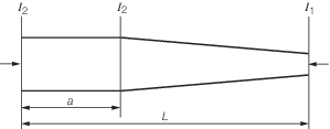
2.21.3 For components
subject to shear stress the critical buckling stress is given by:
-
For τb <
0,29σy
-
For τb ≥
0,29σy
where
|
τb
|
= |
critical
shear buckling stress |
|
b
|
= |
smallest
plate dimension |
|
a
|
= |
plate
length corresponding to b
|
|
Ks
|
= |
shear buckling constant, defined as follows: |
|
α |
= |

|
|
μ |
= |
Poisson’s
ratio |
The graphical representation of K
s is provided in Figure 4.2.8 Shear buckling constant K
s
.
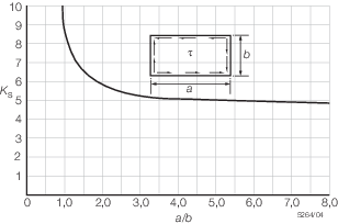
Figure 4.2.8 Shear buckling constant K
s
2.21.4 For components
subject to bending stress, the critical buckling stress is given by:
-
For σbb <
0,5σy
-
For σbb ≥
0,5σy
where
|
σbb
|
= |
critical bending buckling stress |
|
b
|
= |
plate
width, i.e. normal to direction of stress |
|
a
|
= |
plate
length, i.e. in the direction of stress |
|
Kb
|
= |
bending buckling constant, defined as follows: |
|
|
for α ≥  : :
|
|
|
|
|
|
for α <  : :
|
|
|
|
|
α |
= |

|
|
μ |
= |
Poisson’s
ratio |
The graphical representation of K
b is provided in Figure 4.2.9 Bending buckling constant K
b
.
Figure 4.2.9 Bending buckling constant K
b
2.21.5 For components
subject to combined compression and shear stress, the following allowable
stress criteria are to be met:
-
σc ≤ F σcb
-
τ ≤ F τb
-

- where
|
τ |
= |
applied shear
stress |
|
σc
|
= |
applied
compression stress. |
2.21.6 For components
subject to combined bending and shear stress, the following stress
criteria are to be met:
-
σb ≤ F σbb
-
τ ≤ F τb
-

- where
|
σb
|
= |
applied bending stress. |
2.21.7 For components
subject to combined bending and compression stress, the following
allowable stress criteria are to be met:
-
σc ≤ F σcb
-
σb ≤ F σbb
-

2.21.8 For components
subject to combined compression, bending and shear stress, the following
allowable stress criteria are to be met:
-
σc ≤ F σcb
-
σb ≤ F σbb
-
τ ≤ F τb
-

2.22 Allowable stress – Buckling failure of thin walled cylinders
2.22.1 The allowable
stress is to be taken as the critical buckling stress σcb or
σbb, as appropriate, of the component concerned, multiplied
by the allowable factor, F, as defined in Table 4.2.6 Stress factor, F
.
2.22.2 For components
subject to compression the critical buckling stress is given by:
-
For σcb
1 < 0,5σy
-
For σcb
1 ≥ 0,5σy
where

Figure 4.2.10 Compressive buckling
constant
2.22.3 For components
subject to bending the critical buckling stress is given by:
-
For σbb
1 < 0,5σy
-
For σcb 1
≥ 0,5σy
where

Figure 4.2.11 Bending buckling constant
2.22.4 For components
subject to combined compression and bending, the following allowable
stress criteria are to be met:
| σc ≤ F
σcb
1
|
| σb ≤ F
σbb
1
|
|
|
2.22.5 Buckling
calculations carried out in accordance with recognised National or
International Standards will be considered.
2.23 Allowable stress – Joints and connections
2.23.1 For welded joints, the physical properties of the weld metal are considered
as equal to the parent metal. For full penetration butt welds, the allowable stress is
equal to the allowable stress of the parent material. (see
Ch 4, 2.17 Allowable stress – Elastic failure).
2.23.2 For fillet
welds and partial penetration welds, the allowable stresses are reduced.
Values of these reduced stresses are given in Table 4.2.13 Allowable stresses in
welds. Where F is the stress factor, see
Table 4.2.6 Stress factor, F
. Figure 4.2.12 Stresses in welds shows the stresses in a typical
fillet weld. The actual stress in the fillet welds is to be less than
or equal to the allowable stresses and is to be evaluated as follows:
-
Evaluation of perpendicular
weld stresses:
|
|
|
σ⊥
C–D
|
= |
τ⊥
D–E ≤ 0,7F σy
|
|
|
|
or
|
|
|
|
σ⊥
D–E
|
= |
τ⊥
C–D ≤ 0,7F σy
|
|
-
Evaluation of longitudinal
weld stresses:
τ|| ≤ 0,58F σy
- Combined weld stresses

Table 4.2.13 Allowable stresses in
welds
| Type
of weld
|
Allowable stress
|
| Tension and compression
|
Shear
|
| Full penetration butt weld
|
1,0F
σy
|
0,58F
σy
|
| Fillet welds
|
0,7F σy
|
0,58F σy
|
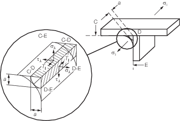
Figure 4.2.12 Stresses in welds
2.23.4 The strength
of joints using pre-tensioned bolts to transmit shear and/or tensile
forces, e.g. high strength friction grip bolts, are to be determined
in accordance with an appropriate and recognised National or International
Standard.
2.23.5 For joints
using precision bolts, defined as turned or cold finished bolts fitted
into drilled or reamed holes whose diameter is not greater than the
bolt diameter by more than 0,4 mm, the allowable stress due to the
externally applied load is given in Table 4.2.14 Allowable stresses for fitted
bolts.
Table 4.2.14 Allowable stresses for fitted
bolts
| Type
of loading
|
Allowable stress
|
| Load cases 1 and 2
|
Load cases 3 and 4
|
| Tension
|
0,4σy
|
0,54σy
|
| Single shear
|
0,38σy
|
0,51σy
|
| Double shear
|
0,57σy
|
0,77σy
|
Tension and
shear
(σyy
2 + 3τ2)1/2
|
0,48σy
|
0,64σy
|
| Bearing
|
0,9σy
|
1,2σy
|
2.23.6 The allowable
stresses for non-fitted bolts are to be taken as per Table 4.2.15 Allowable stresses for non-fitted
bolts.
Table 4.2.15 Allowable stresses for non-fitted
bolts
| Type
of loading
|
Allowable stress
|
| Load cases 1 and 2
|
Load cases 3 and 4
|
| Tension
|
0,4σy
|
0,54σy
|
| Single shear
|
0,32σy
|
0,43σy
|
| Double shear
|
0,36σy
|
0,48σy
|
Tension and shear

|
0,48σy
|
0,64σy
|
| Bearing
|
0,7σy
|
0,9σy
|
2.23.7 Where joints
are subjected to fluctuating or reversal of load across the joint
the bolts are to be pre-tensioned by controlled means to 70 per cent
to 90 per cent of their yield stress.
2.23.8 Black bolts
(ordinary grade bolts) are not to be used for primary joints or joints
subject to fatigue.
2.23.9 Carbon steel
bolts are to be specified in accordance with ISO 898 part 1. Bolts
are to be selected within the range 8.8 to 10.9 (inclusive). Applications
for use of 12.9 bolts will be subject to special consideration. Bolt
materials in other materials such as stainless steels are to be specified
in accordance with a National or International Standard.
2.23.10 Alternative
proposals for the calculation of allowable bolt stresses in accordance
with an appropriate and recognised National or International Standard
will be specially considered. The requirements in the standard need
to provide sufficient equivalence to the requirements given in this
section and need to be agreed with LR.
2.24 Slewing ring and slewing ring bolting
2.24.1 The crane
manufacturer is to submit plans of the slewing ring, the bolting arrangement,
crane and pedestal structure in way of the slewing ring and calculations
giving static and fatigue design loads and allowable stresses for
the ring and bolting arrangement.
2.24.2 The ring
mounting flanges are to be rigid and the bolting equally spaced around
the complete circumference of the ring. Mating surfaces are, in general,
to be steel to steel and packing material is not recommended between
joint faces. Non-equally spaced bolts are only acceptable on the compression
side of the crane house. The number of bolts on the compression side
shall not be less than half of the number of bolts on the tension
side.
2.24.3 Bolts are
to be pre-tensioned by controlled means to 70 to 90 per cent of their
yield stress. Pre-tensioning is to be in accordance with the bearing
manufacturer’s instructions and, in general, pre-tensioning
by bolt torqueing up to bolt size M30 may be used. Beyond this, pre-tensioning
must be carried out by hydraulic tensioning device and elongation
of the bolts measured to determine pre-load. Alternative methods of
pretensioning will be specially considered as long as they are reasonably
technically equivalent to the above methods.
2.24.4 Slewing
ring bolts are to comply with ISO 898-1 and in general not to exceed
Grade 10.9. Special consideration may be given to the application
of 12.9 bolts where adequate precautions are taken to minimise the
risk of hydrogen embrittlement. Threads of all bolt grades are to
be rolled after heat treatment to improve fatigue strength.
2.24.5 The load,
due to external loading, on the most heavily loaded bolt is given
by:
where
|
M
|
= |
design
overturning moment |
|
D
|
= |
pitch
circle diameter of bolts |
Alternative methods for the determination of P will
be considered.
2.24.7 The slewing rings are to comply with the Charpy V-notch impact test
requirements as per Ch 4, 2.25 Materials 2.25.4, as applicable.
2.25 Materials
2.25.3 Slew bearing
applications are to be forged materials and are to be delivered in
the quenched and tempered condition. Materials typically used for
slew bearing applications are 34CrNiMo6 or 42CrMo4 or equivalents.
Where other material grades or manufacturing processes are proposed,
special consideration will be required.
2.25.4 For worldwide
ship operation, slew bearings are to be subject to a Charpy V-notch
impact test at room temperature, the minimum average test requirement
is 34J. For ship operations below –10°C the Charpy V-notch
impact test minimum average requirement is 42J at a test temperature
of –20°C.
2.26 Rope safety factors and sheave ratio
2.26.1 The rope
safety factor for both running and standing application for cranes
with SWL greater than 10 t and less than 160 t is given by:
where
|
SF
|
= |
minimum
safety factor required |
|
SWL |
= |
safe working
load of crane, in tonnes |
For cranes with SWL ≤ 10 t, SF = 5,0
and SWL ≥ 160 t, SF = 3,0.
This is represented graphically in Figure 4.2.13 Rope safety factor versus crane
SWL.
The rope safety factor
SF may be reduced for Cases 3 and 4 (see
Ch 4, 2.15 Load combinations 2.15.1 and Table 4.2.6 Stress factor, F
) by a factor of  . .
The safety factor SF for both the luffing and
hoisting system is to be determined using the maximum SWL for each reeving arrangement.

Figure 4.2.13 Rope safety factor versus crane
SWL
2.26.2 The required
minimum breaking load of the rope is given by:
where
|
BL
|
= |
the
required minimum breaking load of the rope |
|
L
r
|
= |
the load in the rope due to consideration of the unfactored
live load, rope weights and jib weight as appropriate, taking due
account of the number of parts in the rope system and the friction
in the sheaves over which the rope passes. |
2.26.4 The effects
of sheave friction are to be taken into consideration by usually applying
2 per cent for ball or roller bearing sheave and 5 per cent for plain
or bushed bearing sheaves. Lower friction values will be specially
considered. For the calculation of reeving systems taking into account
the effects of sheave friction, see
Ch 2, 2.4 Friction allowance.
|