
Section
9 Consumables for welding aluminium alloys
9.1 General
9.1.2 Approval
will be indicated by the grade shown in Table 11.9.1 Requirements for butt weld
tests. Plate of the corresponding type of aluminium alloy
and of appropriate thickness is to be used for the preparation of
the weld test assemblies, and may be of any temper listed in LR Rules.
Table 11.9.1 Requirements for butt weld
tests
| Consumable Approval Grade
(see Note 1)
|
Base material used for the
test
|
Tensile strength N/mm2
minimum
|
Bend test ratio 
|
| LR RA/LR WA
|
5754
|
190
|
3
|
| LR RB/LR WB
|
5086
|
240
|
6
|
| LR RC1/LR WC1
|
5083
|
275
|
6
|
LR RC2/LR WC2
(see Note 2)
|
5383 or 5456
|
290
|
6
|
LR RC3/LR
WC3
(see Note 2)
|
5059
|
330
|
6
|
LR RD/LR
WD
(see Note 4)
|
6005A
|
170
|
6
|
|
|
6061
|
170
|
6
|
|
|
6082
|
170
|
6
|
Note
1. The prefixes ‘R’ and ‘W’ indicate
‘rod’ form (for Gas Tungsten Arc Welding (GTAW)) or ‘wire’ form (for
Gas Metal Arc Welding (GMAW) and GTAW).
|
Note
2. Approval of grade LR RC2/LR WC2
confers approval of 5383, 5456 and 5083 base material grade.
|
Note
3. Approval of grade LR RC3/LR WC3
confers approval of 5059, 5383, 5456 and 5083 base material
grades.
|
Note
4. Approval of grade LR RD/LR WD confers
approval of 6005A, 6061 and 6082 base material grades.
|
9.1.3 The welding
technique will be indicated in the approval grading by a letter:
|
m
|
= |
manual multi-run
welding (GTAW), |
|
S
|
= |
semi-automatic
multi-run welding (GMAW), |
|
M
|
= |
automatic multi-run
welding (GTAW or GMAW), |
|
T
|
= |
automatic two-run
welding (GMAW). |
9.1.4 The compositions
of the shielding gas and the filler/electrode wire are to be reported.
9.1.5 Approval
granted using the multi-run technique for a specific filler/electrode
wire with a gas in one of the groups listed in Table 11.9.2 Shielding gas compositions will extend to any other
gas compositions within that same group, provided that the gas composition
is within the range recommended by the consumable manufacturer, subject
to agreement with LR.
Table 11.9.2 Shielding gas compositions
| Group
|
Gas composition (Vol. %)
(see Note)
|
| Helium
|
Argon
|
| I-1
|
—
|
100
|
| I-2
|
100
|
—
|
| I-3
|
>0
≤33
|
Remainder
|
| I-4
|
>33
≤66
|
Remainder
|
| I-5
|
>66
≤95
|
Remainder
|
| S
|
Special gas
|
Note Gases of other composition (mixed gases) or special purity
may be considered as special gases and will require separate approval
tests.
|
9.1.6 Approval
granted for the two-run technique will be for a specific shielding
gas composition; additional tests may be required if a change in shielding
gas composition is sought.
9.1.7 On completion
of welding, assemblies are to be allowed to cool naturally to ambient
temperature. Welded test assemblies and test specimens are not to
be subjected to any heat treatment after welding except for the alloy
Grades 6005A, 6061 and 6082. These are to be allowed to naturally
age at ambient temperature for a period of 72 hours from the completion
of welding, before testing is carried out. A second solution heat
treatment is not permitted.
9.1.8 All butt
test assemblies are to be subjected to both radiographic and visual
examination and imperfections such as lack of fusion, lack of penetration,
cavities, inclusions, pores and cracks assessed in accordance with
Intermediate Level C of ISO 10042, aided where necessary by dye penetrant
and ultrasonic examination.
9.1.9 Fillet weld
test assemblies and macro-sections are to be visually examined for
imperfections, such as lack of fusion, lack of penetration, cavities,
inclusions, pores and cracks, in accordance with Intermediate Level
C of ISO 10042, aided where necessary by radiographic and dye penetrant
examination.
9.2 Approval tests for manual, semi-automatic and automatic multi-run
techniques
9.2.1 Plate of
the corresponding type of aluminium alloy and of appropriate thickness
is to be used for the preparation of the weld test assemblies.
9.2.2 The welding
parameters are to be within the range recommended by the manufacturer
and are to be reported.
9.3 Deposited metal test assembly
9.3.2 The chemical
composition of the plate used for the assembly is to be compatible
with the weld metal.
9.3.3 The thickness
of the plate used, and the length of the assembly, are to be appropriate
to the welding process. The plate thickness is to be not less than
12 mm.
9.3.4 For the
approval of filler wire/gas and electrode wire/gas combinations for
manual or semi-automatic welding by GTAW or GMAW, one test assembly
is to be welded using any size of wire within the range for which
approval is sought.
9.3.5 For automatic
multi-run approval, one test assembly is to be welded by the respective
process using the recommended diameter of wire.
9.3.6 The weld
metal is to be deposited in multi-run layers in accordance with normal
practice. The direction of deposition of each layer is to alternate
from each end of the plate.
9.3.7 The deposited
weld metal in the assembly is to be analysed and reported including
the contents of all significant elements. The elements reported will
be dependent on the type of aluminium alloy for which approval of
the consumables is requested. The results of the analysis are not
to exceed the limit values specified in the standards or by the manufacturer,
the narrower tolerances being applicable in each case.
9.4 Butt weld test assemblies
9.4.1 Plate of
the corresponding type of aluminium alloy and of an appropriate thickness
is to be used for the preparation of the test assemblies.
9.4.2 In order
to ensure sound and representative welds, it is essential that test
assemblies are cleaned and degreased prior to welding. Assemblies
as shown in Figure 11.9.2 Butt weld test assembly (positional, multi-run technique) are to
be prepared for each welding position (downhand, horizontal-vertical,
vertical-upward, vertical-downward, and overhead) for which the consumable
is recommended by the manufacturer; except that consumables satisfying
the requirements for downhand and vertical-upward positions will be
considered as also complying with the requirements for the horizontal-vertical
position. Any wire diameter(s) to be approved may be used.
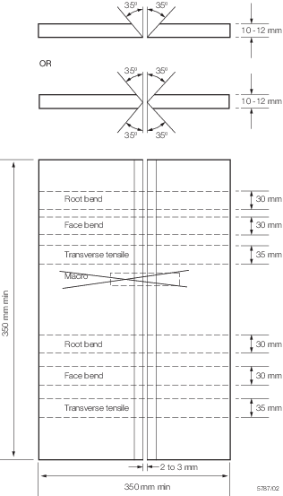
Figure 11.9.2 Butt weld test assembly (positional, multi-run technique)
9.4.3 One assembly,
as shown in Figure 11.9.3 Butt weld test assembly (downhand, multi-run technique), is to
be prepared for welding in the downhand position. The assembly is
to be welded using, for the first run, wire of the smallest diameter
recommended by the manufacturer and, for the remaining runs, wire
of the largest diameter to be approved.
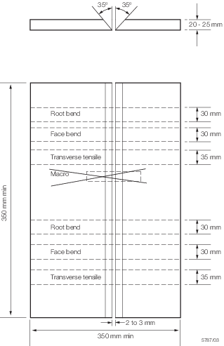
Figure 11.9.3 Butt weld test assembly (downhand, multi-run technique)
9.4.4 The welding
conditions are to be in accordance with the recommendations of the
manufacturer and are to be reported in detail.
9.4.5 The welded
assemblies are to be subjected to NDE. Imperfections are to be assessed
in accordance with Ch 11, 9.1 General 9.1.8.
9.4.8 The bend
test specimens are to be bent around a former having a diameter not
more than the number of times the thickness of the test specimen,
as shown in Table 11.9.1 Requirements for butt weld
tests, and
can be considered as complying with the requirements if, after bending
to an angle of not less than 180°, no crack or other open defect
exceeding 3 mm in length can be seen on the outer surface. Flaws appearing
at the corners of a test specimen may be ignored.
9.4.9 In order
to obtain uniform bending of the bend test specimens, it is recommended
that the wrap-around or guided bend test using a roller method is
employed.
9.5 Fillet weld test assembly
9.5.1 When approval
is being sought for both butt and fillet welding, one assembly is
to be prepared and welded in the horizontal-vertical position and
tested in accordance with the appropriate requirements of Ch 11, 3.5 Fillet weld test assemblies, except that the plates are to be
of an aluminium alloy compatible with the weld metal, that no hardness
tests are required and that for automatic multi-run approval only
one fillet weld bead is to be made using the recommended wire diameter.
In this case, the bead size is to be as large as the maximum single
bead size recommended by the manufacturer for fillet welding.
9.5.2 When approval
is being sought for fillet welding only, one assembly is to be prepared
and welded in each position for which approval is sought, and tested
as detailed in Ch 11, 9.5 Fillet weld test assembly 9.5.1.
9.6 Approval tests for two-run technique
9.6.1 Two butt
weld test assemblies are to be prepared using the following plate
thicknesses:
-
one with the maximum
thickness for which approval is requested,
-
one with a thickness
approximately one half to two thirds that of the maximum thickness.
9.7 Butt weld test assemblies (two-run technique)
9.7.2 The wire
diameter, edge preparation, welding current, arc voltage and travel
speed are to be in accordance with the manufacturer's recommendations
and are to be reported.
9.7.3 Each butt
weld is to be made in two runs, one from each side. After completion
of the first run the assembly is to be left in still air until it
has cooled to less than 50°C.
9.7.4 The welded
assemblies are to be subjected to NDE. Imperfections are to be assessed
in accordance with Ch 11, 9.1 General 9.1.8.
9.7.5 The test
specimens as shown in Figure 11.9.4 Butt weld test assembly (two-run technique) are
to be prepared from each test assembly. The edges of the discards
are to be polished and etched, and must show complete fusion and inter-run
penetration of the welds. Each cut in the assembly is also to be examined
to confirm that complete fusion and penetration have been achieved.
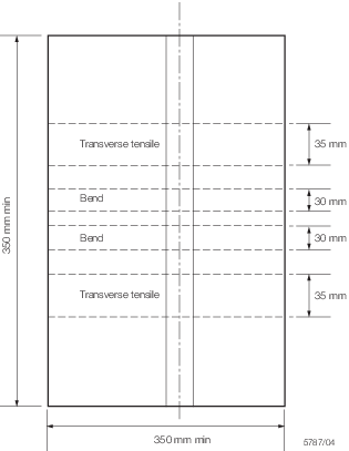
Figure 11.9.4 Butt weld test assembly (two-run technique)
9.8 Annual tests
|