
Section
2 Rudders
2.1 Application
2.1.1 This Section applies to ordinary profile rudders, and to some enhanced
profile rudders with special arrangements for increasing the rudder force, as
defined in Table 13.2.2 Rudder profiles.
2.2 Design considerations
2.2.1 Effective means are to be provided for supporting the weight of the rudder
without excessive bearing pressure, e.g. by a rudder carrier attached to the upper part
of the rudder stock. The hull structure in way of the rudder carrier is to be suitably
strengthened.
2.2.2 Suitable arrangements are to be provided to prevent the rudder from
lifting.
2.2.3 In rudder trunks which are open to the sea, a seal or stuffing box is to be
fitted above the deepest load waterline, to prevent water from entering the steering
gear compartment and the lubricant from being washed away from the rudder carrier. If
the top of the rudder trunk is below the deepest load waterline, two separate stuffing
boxes are to be provided. Rudder trunk boundaries, where exposed to the sea, are to have
a corrosion protection coating applied in accordance with the manufacturer’s
instructions.
2.3 Materials
2.3.2 Stern frames, rudder horns, shaft brackets, rudder stocks, pintles,
coupling bolts, keys, and other rudder members are to be made of rolled, forged or
cast carbon-manganese steel in accordance with Ch 3 Rolled Steel Plates, Strip, Sections and Bars, Ch 4 Steel Castings and Ch 5 Steel Forgings of the Rules for the Manufacture, Testing and Certification of Materials, July 2022. The
requirements for stern frames, rudder horns and shaft brackets are to be in
accordance with Pt 3, Ch 6, 7 Sternframes and appendages.
2.3.3 For rudder stocks, pintles, coupling bolts and keys the minimum specified
yield stress is not to be less than 200 N/mm2.
2.3.4 For rudder stocks, pintles, coupling bolts and keys having a specified
minimum yield stress differing from 235 N/mm2, the material factor,
k is to be determined in accordance with Table 13.2.1 Rudder material factor,
k:
2.3.5 For rudder blade and internal structure having a specified minimum
yield stress between 235 N/mm 2 and 355 N/mm 2, the material
factor, k is to be determined in accordance with Table 13.2.1 Rudder material factor,
k.
Table 13.2.1 Rudder material factor,
k
| Specified minimum yield stress, σo
(N/mm2)
|
k
|
| σo > 235
|
|
| σo ≤ 235
|
|
|
Note 1. The
specified minimum yield stress is not to be taken as greater
than 70 per cent of the ultimate tensile strength.
Note 2.The
specified minimum yield stress is not to be taken as greater
than 450 N/mm2.
|
2.4 Welding and design details
2.4.1 Slot-welding is to be limited as far as possible. Slot welding is not to be used in
areas subject to large in-plane stresses transverse to the slots or in way of
cut-outs of semi-spade rudders. Continuous butt welding with backing may be accepted
in lieu of slot welds. When continuous butt welding is applied, the root gap is to
be between 6-10 mm. The bevel angle is to be at least 15°.
2.4.2 When slot welding is applied, the length of individual slots is to be not less than
75 mm with a minimum breadth of 2 times the plate thickness. The distance between
ends of adjacent slots is to be not greater than 125 mm. The slots are to be fillet
welded around the edges and filled with a suitable compound, e.g. epoxy putty. Slots
are not to be filled with weld. The ends of slots are to be rounded.
2.4.3 The rudder, in way of rudder horn recesses of semi-spade rudders, are to
have well radiused corners. The corner radii except in way of solid part in cast
steel are not to be less than 5 times the local rudder plate thickness, but in no
case less than 100 mm. Welding in the rudder side plating is to be positioned away
from these corner radii. The weld connecting the side plate and the leading edge
plate in way of these radiused corners is to be ground smooth.
2.4.4 Welds between plates and forged or cast parts or very thick plating are to be made as
full penetration welds. In way of highly stressed areas e.g. cut-outs of semi-spade
rudders and upper parts of spade rudders, cast or welded on ribs are to be arranged.
Two sided full penetration welding is normally to be arranged. Where back welding is
impossible welding is to be performed against ceramic backing bars or equivalent.
Steel backing bars may be used and are to be continuously welded on one side to the
heavy piece.
2.5 Equivalence
2.5.1 Lloyd’s Register (hereinafter referred to as LR) may accept alternatives to
the requirements given in this Section, provided they are deemed to be equivalent.
2.5.2 Direct analyses adopted to justify an alternative design are to take into
consideration all relevant modes of failure, on a case by case basis. These failure
modes may include, amongst others: yielding, fatigue, buckling and fracture.
Possible damages caused by cavitation are also to be considered.
2.5.3 If deemed necessary by LR, lab tests, or full scale tests may be requested to
validate the alternative design approach.
2.6 Rudder force
2.6.1 The lateral rudder force at the centre of pressure is to be determined
for both ahead and astern conditions as follows:
where
|
A |
= |
rudder blade area, in m2. |
|
V |
= |
maximum service speed, in knots, for both the ahead and astern
conditions. |
| = |
Vahead is to be taken as the maximum service speed at
the summer load waterline at maximum propeller RPM and corresponding
engine MCR. Where this speed is less than 10 knots,
Vahead is to be replaced by the following
expression:
|
| = |
Vastern, is to be taken as the maximum astern speed or
0,5Vahead, whichever is the greater. |
|
K1 |
= |
aspect ratio correction factor |
| = |

|
|
λ |
= |
 but is not to be taken greater than
2. but is not to be taken greater than
2. |
|
hR |
= |
mean height, in m, of the rudder blade, see
Figure 13.2.1 Rudder co-ordinate system; |
|
At |
= |
sum of rudder blade area A and area of rudder post or rudder horn, if
any, within the mean height hR, in m2. |
|
K2 |
= |
rudder profile coefficient, see Table 13.2.2 Rudder profiles; |
|
K3 |
= |
0,8 for rudders outside the propeller jet. |
| = |
1,15 for rudders behind a fixed propeller nozzle. |
| = |
1,0 otherwise. |

Figure 13.2.1 Rudder co-ordinate system
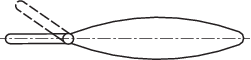
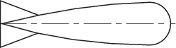
Table 13.2.2 Rudder profiles
| Profile Type
|
K2
|
| Ahead condition
|
Astern condition
|
| NACA-00 series
|
1,10
|
0,80
|
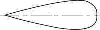
|
| Flat sided
|
1,10
|
0,90
|

|
| Hollow
|
1,35
|
0,90
|

|
| High lift rudders
|
1,70
|
1,30
|
|
| Fish tail
|
1,40
|
0,80
|
|
| Single plate
|
1,00
|
1,00
|
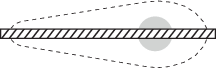
|
| Mixed profiles
|
1,21
|
0,90
|
|
Note For rudder profiles not defined above, the value of
K2 may be determined on the basis of
experimental results. These results are to be submitted for
consideration.
|
2.7 Rudder torque for rudder blades without cut-outs
2.7.1 The maximum rudder torque, QR, is to be determined from
both the ahead and astern conditions as follows:
where
|
CR |
= |
lateral force acting on the rudder, as defined in Pt 3, Ch 13, 2.6 Rudder force 2.6.1. |
|
r |
= |
distance from the centre of pressure to the centreline of the rudder
stock. |
| = |
c (α – k1), in m. |
|
c |
= |
mean breadth of the rudder blade, (the mean chord length),
in m, see
Figure 13.2.1 Rudder co-ordinate system. |
|
α |
= |
relative centre of pressure along the chord length, see
Table 13.2.3 Relative centre of pressure
along the chord length, α. |
|
k1 |
= |
ratio of the rudder blade area forward of the rudder stock centreline,
to the rudder blade area: |
| = |
 |
|
Af |
= |
portion of the rudder blade area situated ahead of the centreline of the
rudder stock. |
For the ahead condition the rudder torque, QR is not to be
taken less than:
Table 13.2.3 Relative centre of pressure
along the chord length, α
| Condition
|
Behind fixed structure
|
Not behind a fixed structure
|
| Ahead
|
0,25
|
0,33
|
| Astern
|
0,55
|
0,66
|
|
Note Fixed structure is defined as any relatively stationary
structure immediately ahead of the rudder, for example rudder
horns of semi-spade rudders.
|
2.8 Rudder torque for rudder blades with cut-outs (semi-spade rudders)
2.8.1 The maximum rudder torque, QR, is to be determined
from both the ahead and astern conditions, for rudder blades with cut-outs, as
follows. The pressure distribution for rudder blades with cut-outs is assumed to be
proportional to the areas above and below the base of the cut-out. The rudder blade
area, A, is to be divided into parts as per Figure 13.2.2 Rudder Areas.
where
|
QR1 |
= |
CR1
r1. |
|
QR2 |
= |
CR2
r2. |
|
CR |
= |
lateral force acting on the rudder, as defined in Pt 3, Ch 13, 2.6 Rudder force 2.6.1 |
|
CR1 |
= |
 |
|
CR2 |
= |
 |
|
r1 |
= |
c1(α – k1), in m. |
|
r2 |
= |
c2(α – k2), in m. |
|
c1 |
= |
mean breadth, in m, of partial area
A1. |
|
c2 |
= |
mean breadth, in m, of partial area
A2. |
|
α |
= |
relative centre of pressure along the chord length,
see
Table 13.2.3 Relative centre of pressure
along the chord length, α. |
|
K1 |
= |
 |
|
K2 |
= |
 |
For the ahead condition the rudder torque, QR is not
to be taken less than:
|
QR |
= |
 Nm Nm |
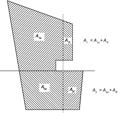
Figure 13.2.2 Rudder Areas
2.9 Rudder strength calculation
2.9.1 The rudder force and resulting rudder torques as given in Pt 3, Ch 13, 2.6 Rudder force, Pt 3, Ch 13, 2.7 Rudder torque for rudder blades without cut-outs or Pt 3, Ch 13, 2.8 Rudder torque for rudder blades with cut-outs (semi-spade rudders), cause bending moments and shear forces in the rudder
body, bending moments and torques in the rudder stock, supporting forces in pintle
bearings and rudder stock bearings and bending moments, shear forces and torques in
rudder horns and heel pieces. The rudder body is to be stiffened by horizontal and
vertical webs enabling it to act as a bending girder.
2.9.2 The bending moments, shear forces and torques as well as the reaction
forces described in Pt 3, Ch 13, 2.9 Rudder strength calculation 2.9.1 are to be determined by direct calculations or where
otherwise stated by an approximate simplified formulae. For rudders supported by
sole pieces or rudder horns these structures are to be included in the calculation
model in order to account for the elastic support of the rudder body.
2.10 Rudder stock scantlings
2.10.2 Before significant reductions in rudder stock diameter due to the
application of steels minimum specified with yield stresses exceeding 235
N/mm2 are granted, LR may require the evaluation of the rudder stock
deformations. Large deformations of the rudder stock are to be avoided in order to
avoid excessive edge pressures in way of bearings.
2.10.3 For spade rudders the stock diameter corrected for higher tensile steel
is to be greater than 90 per cent of the uncorrected stock diameter unless direct
calculations are submitted showing that the slope of the stock at the lowest main
bearing does not exceed 0,0035 when the rudder blade is loaded by a lateral force of
CR, as defined in Pt 3, Ch 13, 2.6 Rudder force 2.6.1, acting at the centre of pressure.
2.10.4 For rudders having an increased diameter of the rudder stock in way of
the rudder, the increased diameter is to be maintained to a point as far as
practicable above the top of the lowest bearing. The diameter may then be tapered to
the diameter required in way of the tiller. The length of the taper is to be at
least three times the reduction in diameter. Particular care is to be taken to avoid
the formation of a notch at the upper end of the taper, see
Figure 13.2.3 Rudder stock taper.
2.10.5 Sudden changes of section or sharp corners in way of the rudder coupling,
jumping collars and shoulders for rudder carriers, are to be avoided. Jumping
collars are not to be welded to the rudder stock. Keyways in the rudder stock are to
have rounded ends and the corners at the base of the keyway are to be radiused.
Table 13.2.4 Rudder stock diameter
| Item
|
Requirement
|
| (1) Rudder stock diameter due to combined
loads
|
|
| (2) Rudder stock diameter required for
transmission of the rudder torque (e.g. in way of tiller)
|

|
| Symbols
|
| QR = maximum rudder torque, in Nm, as
calculated in Pt 3, Ch 13, 2.8 Rudder torque for rudder blades with cut-outs (semi-spade rudders)
|
| M =
bending moment, in Nm, at the section of the rudder stock under
consideration, see
Pt 3, Ch 13, 2.9 Rudder strength calculation 2.9.2.
|
|
Note 1. If direct calculations are not carried out, then the
following approximate formulae may be applied:
|
| For rudders
with a heel support;
|
| For spade
rudders;
|
| For semi-spade
rudders;
|
| where
|
| hR = mean height, in m, of the rudder blade,
see
Figure 13.2.1 Rudder co-ordinate system.
|
| hc = the distance, in m, from the centroid of
the rudder blade area to the centre of the lowest main
bearing;
|
| c = mean breadth of the rudder blade, (the mean chord
length), in m, see
Figure 13.2.1 Rudder co-ordinate system.
|
| A = rudder blade area, in m2.
|

Figure 13.2.3 Rudder stock taper
Table 13.2.5 Rudder stock permissible stresses
| Mode
|
Permissible stress,
N/mm2
|
| (1) Torsional shear stress,
τt
|

|
| (2) Equivalent stress,
σc
|

|
| Symbols
|
| Equivalent
stress:
|
| Bending
stress:
|
| Torsional stress:
|
| M = bending
moment, in Nm, at the section of the rudder stock under
consideration, see
Pt 3, Ch 13, 2.9 Rudder strength calculation 2.9.2.
|
| dc= actual stock diameter, in mm.
|
2.11 Rudder blade
2.11.5 For spade rudders fitted with a fabricated rectangular mainpiece, the
mainpiece is to be designed with its forward and aft transverse sections at similar
distances forward and aft of the rudder stock transverse axis.
2.11.6 Internal surfaces of double plate rudders are to be efficiently coated.
Alternatively, where it is intended to fill the rudder with plastic foam or use a
corrosion inhibitor, details are to be submitted. Means for draining the rudder are
to be provided.
Table 13.2.6 Double plated rudder
construction
| Item
|
Requirement
|
| (1) Rudder side, top and bottom plating
|

|
| (2) Webs, vertical and horizontal
|
tw ≥ 0,7t but is not to be less than 8 mm
|
| (3) Nose plate
|
tn ≥ 1,25t but need not exceed 22 mm
|
(4)
Mainpiece,
(see Notes 1 and 2)
|
Rectangular
(fabricated)
|
Breadth and width ≥
dc
The side plating of the
mainpiece is to extend 0,2c and is to be in accordance with (1) and
the vertical webs as per (2), but in no case are either to be less
than tM.
|
 (see Note
3 and 4) (see Note
3 and 4)
|
| Tubular
|
Inside diameter ≥
dc
|
| Symbols
|
| T = draught, in m, as given in Pt 3, Ch 1, 6.1 Principal particulars;
|
| CR = rudder force, in N, as defined in Pt 3, Ch 13, 2.6 Rudder force 2.6.1;
|
| A = rudder area, in m2;
|
 ; max. 1,00 if b/s ≥ 2,5 ; max. 1,00 if b/s ≥ 2,5
|
| kL = material factor, as defined in Table 2.1.1 Values of k
L
|
| s = smallest unsupported width of plating in m
|
| b = greatest unsupported width of plating in m
|
| c = chord length in m, as defined in Figure 13.2.1 Rudder co-ordinate system.
|
Note 3. The stock
diameter to be used for calculating the mainpiece plate
thickness is to be based on the mild steel stock scantlings, as
given in Table 13.2.4 Rudder stock diameter.
Note 4. The
requirement of tM need only be applied to the upper part
of the rudder plate:
- for semi spade rudders; above a point midway
between the lowest pintle and the bottom of the
rudder.
- for spade rudders; above a point one third
of the height of the rudder above the base.
|
Table 13.2.7 Single plate rudder construction
| Item
|
Requirement
|
| (1) Blade thickness
|
The greater of;
 ; or 10 mm. ; or 10 mm.
|
| (2) Arms
|
ta =
tb
|
|
|
The section modulus is not to be less
than:
|
|
|
Za = 0,5 s
C12 V2k cm3
|
| (3) Mainpiece, see Note 1
|
As per Table 13.2.4 Rudder stock diameter
|
| Symbols
|
| s =
spacing of stiffening arms, in m, but is not to exceed 1 m.
|
| V = speed in knots, as defined in Pt 3, Ch 13, 2.6 Rudder force 2.6.1.
|
| C1 = horizontal distance from the aft edge of
the rudder to the centreline of the rudder stock, in m.
|
| KL material factor as defined in Table 2.1.1 Values of k
L
|
|
Note 1. For spade rudders the lower third may be taper down to 0,75
dc.
|
Table 13.2.8 Rudder blade permissible stresses
| Item
|
Permissible stress, N/mm2
|
| Bending stress,
σb
|
Shear stress, τ
|
Equivalent stress,
σc
|
| Rudder blade, clear of
cut-outs
|

|

|

|
| Rudder blade in way of cut-outs, of
semi-spade rudders
|
75
|
50
|
100
|
| Symbols
|
| kL = material factor
as defined in Table 2.1.1 Values of k
L
|
2.12 Connections of rudder blade structure with solid parts
2.12.3 The minimum section modulus, Zs of the cross-section
of the structure of the rudder blade formed by vertical web plates and rudder
plating, which is connected with the solid part where the rudder stock is housed is
to be not less than:
where
|
cs |
= |
coefficient, to be taken equal to: |
| = |
1,0 if there is no opening in the rudder plating or if such openings are
closed by a full penetration welded plate. |
| = |
1,5 if there is an opening in the considered cross-section of the
rudder. |
|
dc |
= |
rudder stock diameter, in mm. |
|
HE |
= |
vertical distance between the lower edge of the rudder blade and the
upper edge of the solid part, in m. |
|
HX |
= |
vertical distance between the considered cross-section and the upper
edge of the solid part, in m. |
|
kL |
= |
material factor for the rudder blade plating, see
Table 2.1.1 Values of k
L
. |
|
ks |
= |
material factor for the rudder stock, see
Pt 3, Ch 13, 2.3 Materials 2.3.4. |
where
|
sv |
= |
spacing between the two vertical webs, in m. |
Where openings for access to the rudder stock nut are not closed by a full
penetration welded plate, they are not to be included in the section modulus
calculations.
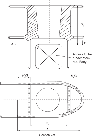
Figure 13.2.4 Cross-section of the
connection between rudder blade structure and rudder stock housing, example with
opening in only one side shown
2.12.5 The thickness of the horizontal web plates connected to the solid parts as well as
that of the rudder blade plating between these webs, is to be not less than the
greater of the following values:
|
tH |
= |
1,2 t mm |
|
tH |
= |
 mm mm |
The increased thickness of the horizontal webs is to extend fore and aft of the solid
part at least to the next vertical web.
2.12.6 The thickness of the vertical web plates welded to the solid part where
the rudder stock is housed as well as the thickness of the rudder side plating above
and below this solid part is to be not less than the values obtained from Table 13.2.9 Thickness of side plating and vertical web plates in way of solid
parts. The increased
thickness is to extend above and below the solid piece at least to the next
horizontal web.
Table 13.2.9 Thickness of side plating and vertical web plates in way of solid
parts
| Type of rudder
|
Thickness of vertical web plates, in mm
|
Thickness of rudder plating, in mm, see Note
1
|
| Rudder blade
without opening
|
Rudder blade
with opening
|
Rudder blade
without opening
|
Area with
opening
|
| Rudder
supported by sole piece
|
1,2
t
|
1,6
t
|
1,2
t
|
1,4
t
|
| Semi-spade
and spade rudders
|
1,4
t
|
2,0
t
|
1,3
t
|
1,6
t
|
| Symbols
|
| t = thickness of the rudder plating, in mm, as
calculated in Table 13.2.6 Double plated rudder
construction
|
| c = chord length in m, as defined in Figure 13.2.1 Rudder co-ordinate system.
|
|
Note 1. The side plating of the mainpiece is to extend at least
0,2c.
|
2.13 Rudder stock flange couplings
2.13.2 For rudders with horizontal coupling arrangements the rudder stock should
be forged when the stock diameter exceeds 350 mm. Where the stock diameter does not
exceed 350 mm the rudder stock may be either forged or fabricated. Where the upper
flange is welded to the rudder stock, a full penetration weld is required and its
integrity is to be confirmed by non-destructive examination. The flange material is
to be from the same welding materials group as the stock. Such rudder stocks are to
be subjected to a furnace post-weld heat treatment (PWHT) after completion of all
welding operations. For carbon or carbon manganese steels, the PWHT temperature is
not to be less than 600°C.
2.13.5 The connecting bolts for coupling the rudder to the rudder stock are to
be positioned with sufficient clearance to allow the fitting and removal of the
bolts and nuts without contacting the palm radius. The surface forming the palm
radius is to be free of hard and sharp corners and is to be machined smooth to the
Surveyor's satisfaction. The surface in way of bolts and nuts is to be machined
smooth to the Surveyor's satisfaction.
2.13.6 Coupling bolts are to be fitted bolts and their nuts are to be locked
effectively.
Table 13.2.10 Horizontal and Vertical flange couplings
| Item
|
Requirement
|
| Horizontal
coupling
|
Vertical
coupling
|
| Number of coupling bolts
|
n ≥ 6
|
n ≥ 8
|
| Diameter of coupling bolts, in
mm
|

|

|
| Thickness of coupling flange,
in mm
|
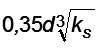
The greater of the following, (see Note 1):
(a) 
(b) 
(c) 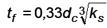 (see
Notes 2 and 3) (see
Notes 2 and 3)
|
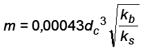
tf = db
|
| Width of flange material
outside the bolt holes, in mm
|
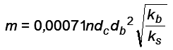
Wf =
0,67db
|
Wf = 0,67db
|
| First moment of area of bolts about centre of coupling, in
cm3
|
|
|
| Stress concentration factor for as built scantlings
|
αasbuilt≤ αmax (see Note
2)
|
-
|
| Symbols
|
| dc = stock diameter, in mm, as calculated in
Table 13.2.4 Rudder stock diameter.
|
| n = total number of bolts.
|
| em = mean distance, in mm, of the bolt axes
from the centre of the bolt system.
|
| ks = material factor for the stock.
|
| kb = material factor for the bolts.
|
| kf = material factor for flange.
|
| db = bolt diameter, in mm.
|
| wf = width of flange material outside the
bolt holes, in mm.
|
| m = first moment of area of bolts about the centre of
the coupling, in cm3.
|

|
| αasbuilt = stress concentration factor for as built
scantlings.
|
| αmax = maximum allowable stress concentration
factor.
|

|
| h = vertical distance, in m, between the centre of
pressure and the centre point of the palm radius, see
Figure 13.2.7 Rudder stock horizontal flange coupling.
|
| kmax = the greater of ks or
kf
|
| R = palm radius, in mm, between the rudder stock and
connection flange.
|
| tf = minimum thickness of coupling flange, in
mm.
|
| tfa = as built flange thickness, in
mm.
|
|
Note 1. Where the
value of db is to be calculated for a number
of bolts not exceeding 8.
Note 3. For a twin
spade rudder arrangement with a single screw, and where the
rudders are positioned within the slipstream of the
propeller:
- the thickness of the palm plate/coupling
flange is not to be less than
- where the stock is welded to the palm plate,
the stock diameter is to be increased by 14 per
cent
|
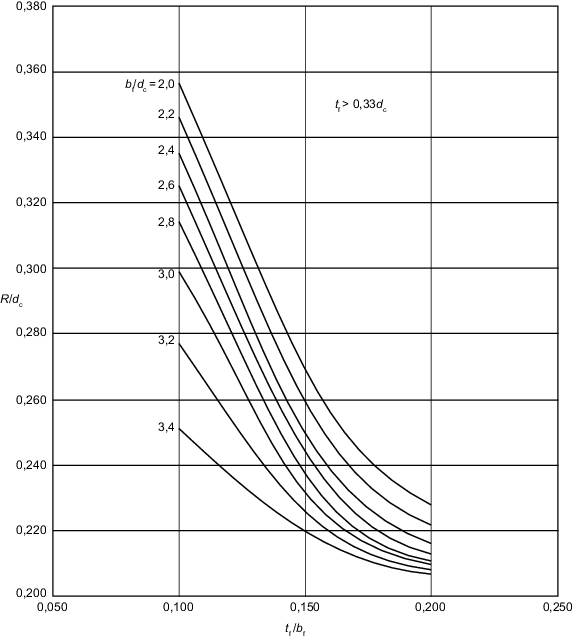
Figure 13.2.5 Rudder stock horizontal flange palm radius for spade rudders
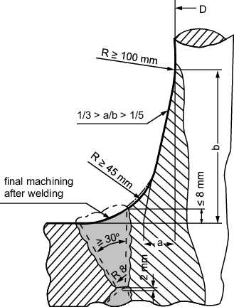
Figure 13.2.6 Welded joint between rudder stock and coupling flange
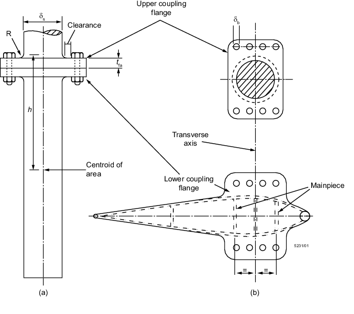
Figure 13.2.7 Rudder stock horizontal flange coupling
2.14 Cone couplings with key
2.14.1 Cone couplings without hydraulic arrangements for mounting and
dismounting the coupling are to have a taper ratio, θt on diameter of 1:8
to 1:12;
where
|
θt |
= |
 |
dc is defined in Figure 13.2.8 Cone coupling with key.
lc is defined in Figure 13.2.9 Cone length and coupling length.
The cone shapes are to fit exactly. The cone coupling is to be secured
by a nut and the nut itself is to be secured, e.g. by a securing plate, see .
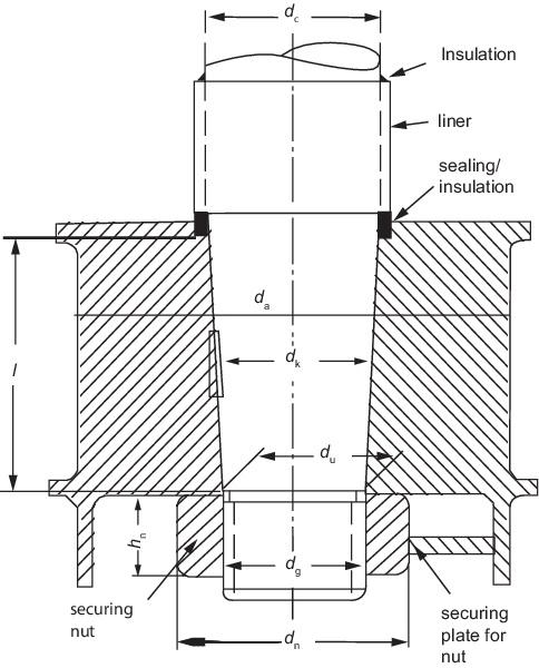
Figure 13.2.8 Cone coupling with key
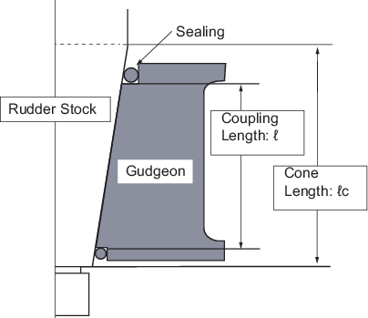
Figure 13.2.9 Cone length and coupling length
2.14.2 The coupling length ℓ is to be, not less than 1,5dc.
2.14.3 For couplings between stock and rudder where a key is provided, the shear area of the
key is not to be less than:
|
as |
= |
 |
where
|
QF |
= |
design yield moment of rudder stock, in Nm. |
|
QF |
= |
0,02664 |
|
dt |
= |
stock diameter, in mm, as calculated in Table 13.2.4 Rudder stock diameter. |
|
dk |
= |
mean diameter of the conical part of the rudder stock, in mm, at the
key. |
|
σF1 |
= |
minimum specified yield stress of the key material, in
N/mm2. |
Where the actual diameter dta is greater than the calculated
diameter dt, the diameter dta is to be used.
However, dta need not be taken greater than 1,145
dt.
2.14.4 The effective surface area of the key (without rounded edges) between key and rudder
stock or cone coupling is not to be less than:
|
ak |
= |
 |
where
|
σF2 |
= |
minimum specified yield stress of the key, stock or
coupling material, in N/mm2, whichever is less. |
2.14.5 The dimensions of the securing nut are to be in accordance with Table 13.2.11 Securing nut dimensions, see also
Figure 13.2.8 Cone coupling with key:
Table 13.2.11 Securing nut dimensions
| Item
|
Requirement
|
| External thread diameter
|
dg ≥ 0,65
dc
|
| Height
|
hn ≥ 0,6
dg
|
| Outer diameter
|
The greater of the following:
- dn ≥ 1,2
du,
- dn ≥1,5
dg
|
| Symbols, see
Figure 13.2.8 Cone coupling with key.
|
| dc = stock diameter, in mm
|
| dg = external thread diameter, in mm
|
| hn = height of securing nut, in mm
|
| dn = minimum distance across flats of
securing nut, in mm
|
| du = inner diameter of securing nut, in
mm
|
2.15 Cone couplings with special arrangements for mounting and dismounting the couplings
2.15.1 Where the stock diameter exceeds 200 mm, the press fit is recommended to
be effected by a hydraulic pressure connection. In such cases the cone is to be more
slender, and is to have a taper ratio, θt, on diameter of 1:12 to 1:20.
2.15.2 In the case of hydraulic pressure connections the nut is to be
effectively secured against the rudder stock or the pintle.
2.15.4 The push-up pressure, Preq is not to be less than the
greater of the two following values:
|
preq1 |
= |
 |
|
preq2 |
= |
 |
where
|
QF |
= |
design yield moment of rudder stock, in Nm, as defined in
Pt 3, Ch 13, 2.14 Cone couplings with key 2.14.3. |
|
dm |
= |
mean cone diameter in, mm =  . . |
|
l |
= |
coupling length in, mm, see
Figure 13.2.8 Cone coupling with key. |
|
Mb |
= |
bending moment in the cone coupling (e.g. in case of spade
rudders), in Nm. |
|
µ0 |
= |
frictional coefficient, to be taken as 0,15. |
|
du |
= |
upper cone diameter, see
Figure 13.2.8 Cone coupling with key |
|
dc |
= |
lower cone diameter, see
Figure 13.2.8 Cone coupling with key |
It has to be proved by the designer that the push-up pressure does not exceed the
permissible surface pressure in the cone. The permissible surface pressure is to be
determined by the following formula:
|
pperm |
= |
 |
2.15.5 The push-up length Δℓ , is to comply with the following formula:
where
|
Δℓ1 |
= |
 |
|
Δℓ2 |
= |
 |
where
2.15.6 In case of hydraulic pressure connections the required push-up force
Pe, for the cone may be determined by the following formula:
|
Pe |
= |
 |
The value 0,02 is a reference for the friction coefficient using oil pressure. It
varies and depends on the mechanical treatment and roughness of the details to be
fixed. Where due to the fitting procedure a partial push-up effect caused by the
rudder weight is given, this may be taken into account when fixing the required
push-up length, subject to approval by LR.
2.16 Pintles
2.16.1 Rudder pintles and their bearings are to be in accordance with the
requirements of this sub-section and Pt 3, Ch 13, 2.17 Bearings.
2.16.3 Where liners are fitted to pintles, they are to be shrunk on or otherwise
efficiently secured. If liners are to be shrunk on, the shrinkage allowance is to be
indicated on the plans. Where liners are formed by stainless steel weld deposit, the
pintles are to be of weldable quality steel and details of the procedure are to be
submitted, see also
Pt 3, Ch 13, 2.17 Bearings 2.17.2.
2.16.4 Where an *IWS (In-water Survey) notation is to be assigned, means are to be
provided for ascertaining the rudder pintle and bush clearances and for verifying the
security of the pintles in their sockets with the vessel afloat.
Table 13.2.12 Pintle requirements
| Item
|
Requirement
|
|
(1) Pintle diameter, in mm
|
|
|
(2) Pintle taper
|
Method of
assembly
|
Taper (on
diameter)
|
|
|
Keyed and
other manually assembled pintles applying locking by securing nut
|
1:8 –
1:12
|
|
|
Pintles
mounted with oil injection and hydraulic nut
|
1:12 –
1:20
|
| (3) Pintle
bearing length
|
dpl ≤ lp ≤ 1,2
dpl
|
| (4) Pintle
housing/gudgeon
|
bg≥ 0,25
dpl
|
| (5) Liner
or bush in way of pintle bearings, in mm
|

|
| Symbols
|
|
k
p = material factor for pintle, as defined in Pt 3, Ch 13, 2.3 Materials 2.3.4
|
| B
= bearing force, in N
|
| d
p = actual pintle diameter measured to the inside of the liner,
in mm
|
| d
pl = diameter measured to the outside of the pintle liner, in
mm
|
| b
g = thickness of pintle housing/gudgeon in way of pintles
(measured from the outside of bush if fitted).
|
|
|
2.17 Bearings
2.17.1 Bearings are to comply with the requirements of Table 13.2.13 Bearings. The fitting of bearings is to
be carried out in accordance with the manufacturer’s recommendations to ensure that
they remain secure under all foreseeable operating conditions.
2.17.2 Where it is proposed to use stainless steel for liners or bearings for
rudder stocks and/or pintles, the chemical composition is to be submitted for
approval. Synthetic rudder bearing materials are to be of a type approved by LR.
When this type of lining material is used, arrangements to ensure an adequate supply
of sea-water to the bearing are to be provided.
Table 13.2.13 Bearings
| Item
|
Requirement
|
| (1) Bearing surface
area
|
 mm2 1 mm2 1
|
| (2) Bearing length
|
The length/diameter ratio of the bearing surface is not to be
greater than 1,2.
|
| (3)
Clearance
|
Bearing material
|
Minimum clearance (on
diameter)
|
| Metal
|
0,001d + 1,0 mm
|
| Synthetic
|
See Notes 1, 2, 3 and
4
|
| (4) Liners and bushes
|
Material
|
Minimum thickness
|
|
|
Metal and synthetic
material
|
8 mm
|
|
|
Lignum vitae
|
22 mm
|
| (5) Main bearing housing wall
thickness, see Note 5
|
Greater than 0,2dc
|
| Symbols
|
| AB = bearing surface, in mm2,
defined as the projected area (length x outer diameter) of
liner
|
| dc = stock diameter, as calculated in Table 13.2.4 Rudder stock diameter, or
pintle diameter as calculated in Table 13.2.12 Pintle requirements
|
| Fbear = bearing force, in N
|
| qa = allowable surface pressure, see
Table 13.2.14 Allowable surface pressure
qa.
|
|
Note 1. If
non-metallic bearing material is applied, the bearing clearance
is to be specially determined considering the material's
swelling and thermal expansion properties. This clearance is not
to be less than 1,5 mm on bearing diameter unless a smaller
clearance is supported by the manufacturer’s recommendation and
there is documented evidence of satisfactory service history
with a reduced clearance.
Note 2. For bearings
which are pressure lubricated the clearance must be restricted
to enable the pressure to be maintained.
Note 3. The value of
the proposed minimum clearance is to be indicated on plans
submitted for approval.
Note 4. Proposals
for higher pressures or other materials will be specially
considered on the basis of satisfactory test results.
Note 5. Where web
stiffening is fitted on the bearing, a reduction in wall
thickness will be considered.
|
Table 13.2.14 Allowable surface pressure
qa
| Bearing material
|
qa
(N/mm2) (see Note 1)
|
| Lignum vitae
|
2,5
|
| White metal, oil
lubricated
|
4,5
|
| Synthetic material with
hardness greater than 60 Shore D (see Note 2)
|
5,5 (see Note
3)
|
| Steel (see Note 4) and
bronze and hot-pressed bronze-graphite materials
|
7,0
|
|
Note 1. Proposals
for higher pressures will be specially considered on the basis
of satisfactory test results.
Note 2. Indentation
hardness test at 23°C and with 50 per cent moisture according to
a recognised standard. Synthetic bearing materials are to be of
an approved type.
Note 3. Surface
pressures exceeding 5,5 N/mm2 may be accepted in
accordance with bearing manufacturer's specification and tests,
but in no case more than 10 N/mm2.
4. Stainless
and wear-resistant steel in an approved combination with stock
liner.
Note
|
|