
Section
7 Sternframes and appendages
7.1 General
7.1.1 Sternframes,
rudder horns, boss end brackets and shaft brackets may be constructed
of cast or forged steel, or may be fabricated from plate.
7.1.2 In castings,
sudden changes of section or possible constrictions to the flow of
metal during casting are to be avoided. All fillets are to have adequate
radii, which should, in general, be not less than 50 to 75 mm, depending
on the size of the casting.
7.1.4 Sternframes,
rudder horns, shaft brackets, etc. are to be effectively integrated
into the ship's structure, and their design is to be such as to facilitate
this.
7.2 Sternframes
7.2.1 The scantlings of sternframes are to be determined from Table 6.7.1 Sternframes. In the case of very large ships, the
scantlings and arrangements may be required to be verified by direct calculations.
Table 6.7.1 Sternframes
| Item
|
Parameter
|
Requirement
|
|
(1) Propeller posts
see Notes 1 and 2
|
|
Cast
steel, see
Figure 6.7.5 Propeller posts
|
Forged
steel, see
Figure 6.7.5 Propeller posts
|
Fabricated mild steel,see
Figure 6.7.5 Propeller posts
|
| l
|
165 mm mm
|
-
|
200 mm mm
|
|
r
|
20 mm mm
|
-
|
18 mm mm
|
|
t
w
|
8 mm mm
(need not exceed 38)
|
need not exceed
30)
|
6 mm mm
|
|
t
1
|
12 mm (min. 19) mm (min. 19)
|
-
|
12 mm mm
|
|
t
2
|
16 mm (min.25) mm (min.25)
|
-
|
-
|
|
w
|
115 mm mm
|
40 mm mm
|
140 mm mm
|
|
A
|
-
|
(10+0,5L)T cm2 where L ≤ 60
m
40T cm2 where L > 60 m
|
-
|
|
(2) Propeller boss,
see Note 3 and Figure 6.7.6 Propeller boss
|
t
b
|
(0,1δTS + 56) mm, but need not exceed 0,3δTS
|
| (3)
Rudder posts or axles
|
|
Single screw with integral
solepiece, see
Figure 6.7.10 Solepieces(a)
|
Single screw with bolted
rudder axle, see
Figure 6.7.7 Rudder axle
|
Twin screw, integral with
hull, see
Figure 6.7.8 Rudder post for twin screw ships
|
|
n
|
-
|
6 (see Note 4)
|
-
|
|
r
|
-
|
-
|
20 mm mm
|
|
r
b
|
-
|
δA
mm
|
-
|
|
t
F
|
-
|
δB
mm
|
-
|
|
t
1
|
-
|
-
|
12 mm mm
|
|
t
2
|
-
|
-
|
15 mm mm
|
|
t
3
|
-
|
-
|
18 mm mm
|
|
w
|
-
|
-
|
120 mm mm
|
|
z
PB1, z
PB2
|
-
|
1,2δPL2 mm
|
-
|
|
Z
T
|
0,147 A
R K2
b(V
0+3)2 cm3
A
R K2
b(V
0+3)2 cm3
|
-
|
-
|
| δA
|
-
|
(25T + 76) mm
but need not exceed 0,9δPL2 mm
|
-
|
| δb
|
-
|
6,25T + 19 mm or 0,225δPL2 mm
whichever is the greater
|
-
|
| δPL1, δPL2 bearing pressure and pintle clearance
|
-
|
As for rudder pintles
(see
Table 13.2.12 Pintle requirements in Chapter
13)
|
-
|
| Symbols
|
|
L, T as defined in Pt 3, Ch 6, 1.4 Symbols and definitions 1.4.1
|
|
|
|
|
|
n
|
= |
number of bolts in palm coupling |
|
|
r
b
|
= |
mean distance of bolt centres from centre of palm, in
mm |
|
|
t
b
|
= |
finished thickness of boss, in mm |
|
|
A
|
= |
cross-sectional area of forged steel propeller post,
in cm2
|
|
|
|
|
|
|
V0 |
= |
maximum service speed, in knots, with the ship in the
loaded condition |
|
|
Z
T
|
= |
section modulus against transverse bending, in
cm3
|
|
|
δb
|
= |
diameter of coupling bolts, in mm |
|
|
δTS
|
= |
diameter of tail shaft, in mm |
|
Note
1. Where scantlings and proportions of
the propeller post differ from those shown in Item (1), the section
modulus about the longitudinal axis of the proposed section normal to
the post is to be equivalent to that with Rule scantlings. t is
to be not less than  (minimum of 19 mm for cast steel sternframes) or as
required by Pt 3, Ch 6, 3.4 Side shell and sheerstrake 3.4.2, whichever is the greater. (minimum of 19 mm for cast steel sternframes) or as
required by Pt 3, Ch 6, 3.4 Side shell and sheerstrake 3.4.2, whichever is the greater.
|
Note
2. On sternframes without solepieces, the
modulus of the post below the propeller boss, about the longitudinal
axis may be gradually reduced to not less than 85% of that required by
Note 1, subject to the same thickness limitations.
|
Note
3. In fabricated sternframes the
connection of the propeller post to the boss is to be by full
penetration welds.
|
Note
4. If more than six bolts are fitted, the
arrangements are to provide equivalent strength.
|
7.2.2 Fabricated
and cast propeller posts and rudder posts of twin screw ships are
to be strengthened at intervals by webs. In way of the upper part
of the sternframe arch, these webs are to line up with the floors.
7.2.3 Rudder
posts and propeller posts are to be connected to floors of increased
thickness, see
Pt 3, Ch 6, 6.1 Bottom structure.
Table 6.7.2 Permissible stresses for sole
pieces
| Mode
|
Permissible stress
|
| (1) Equivalent
stress
|
115/K
0 N/mm2
|
| Symbols
|
|
σe |
= |
equivalent stress |
| = |
 N/mm2 N/mm2 |
|
|
σb
|
= |
bending stress |
| = |
 N/mm2 N/mm2 |
|
|
τT
|
= |
shear stress |
| = |
 N/mm2 N/mm2 |
|
|
MB
|
= |
bending moment, in Nm, at the section considered |
| = |
B
1
x
|
|
|
B
1
|
= |
supporting force, in N, in pintle bearing |
| = |
0,5P
L
|
|
|
P
L
|
= |
rudder force, in N, as calculated in Ch 13,2 |
|
|
x |
= |
distance, in metres, from centre of rudder stock to
section under consideration |
|
|
|
|
A
s
|
= |
sectional area, in mm2, of solepiece |
|
7.3 Sole pieces
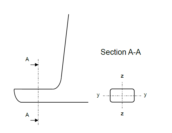
Figure 6.7.1 Solepiece
7.3.1 The scantlings of sole pieces are to be not less than those required by Table 6.7.3 Sole pieces scantlings:
Table 6.7.3 Sole pieces scantlings
| Item, see
Figure 6.7.1 Solepiece
|
Minimum requirements
|
|
Section modulus about the vertical (z)-axis, Zz
|
|
|
Section modulus about the transverse (y)-axis, Zy
|
|
|
Section area, As
|
|
| Symbols
|
|
|
1. For dredging and reclamation craft classed 'A1
protected waters service', the scantlings of an ‘open’ type
solepiece are to be such that:
- Zz = 0,625 Zz
- The cross-sectional area is not less than 18
cm2
- The depth is not less than two-thirds of the width
at any point.
Note 2. In fabricated solepieces, transverse webs are to
be fitted spaced not more than 760 mm apart. Where the
breadth of the solepiece exceeds 900 mm, a centreline
vertical web is also to be fitted.
|
7.3.2 The solepiece is to be dimensioned such that the stresses do not exceed the
permissible stresses given in Table 6.7.4 Permissible stresses for solepieces.
Table 6.7.4 Permissible stresses for solepieces
| Mode
|
Permissible stress
|
| (1) Equivalent stress
|
|
| Symbols
|
|
|
7.4 Rudder horns
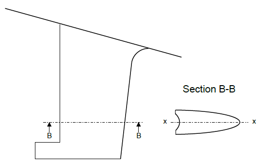
Figure 6.7.2 Rudder horn
7.4.1 Rudder horns are to be effectively integrated into the main hull structure.
7.4.2 The rudder horn side plating should be carried through the ship’s bottom shell plating
and aligned with primary members. Brackets or stringers are to be fitted on the inside
of the rudder horn to align with the ship’s adjoining bottom shell plating, see
Figure 6.7.3 Rudder horn integration.
7.4.3 A number of transverse webs of the rudder horn should be carried through the ship’s
bottom shell up to the inner bottom or bottom deck. These rudder horn transverse webs
should be fitted in line with strengthened plate floors.
7.4.4 Where practicable the rudder horn should be connected to the ship’s centreline bulkhead.
7.4.5 Scallops in way of the connection between the rudder horn transverse webs and the ship’s
adjoining bottom shell plating are to be avoided.
7.4.6 The weld at the connection between the rudder horn plating and the ship’s bottom shell
is to be full penetration. The welding radius is to be as large as practicable and may
be obtained by grinding.
7.4.7 When the connection between the rudder horn and the hull structure is designed as a
curved transition into the hull plating, special consideration is to be given to the
effectiveness of the rudder horn plate bending and to the stresses in the transverse web
plates.
7.4.8 The ship’s bottom shell plating is to be increased in thickness in way of the rudder
horn. Where the horn plating is radiused into the shell plating, the radius at the shell
connection is to be not less than:
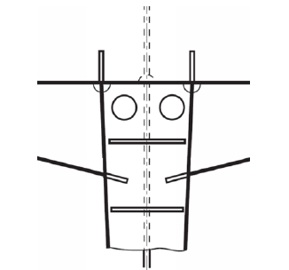
Figure 6.7.3 Rudder horn integration
7.4.9 The bending moments and shear forces are to be determined by direct calculations.
Table 6.7.6 Permissible stresses for rudder
horns
| Mode
|
Permissible stress
|
| (1) Shear stress
|
|
| (2) Equivalent
stress
|
|
| Symbols
|
|
σe
|
= |
equivalent stress |
| = |
 |
|
|
|
|
|
|
B
1
|
= |
supporting force in the pintle bearing, in N |
|
|
A
h
|
= |
effective shear area, of rudder horn in y-direction,
in mm2 |
|
|
|
|
M
T
|
= |
torsional moment at the section considered, in
Nm |
|
|
A
T
|
= |
area in the horizontal section enclosed by the rudder
horn, in mm2
|
|
|
t
h
|
= |
plate thickness of rudder horn, in mm |
|
|
|
Table 6.7.7 Rudder coefficient k
R
| Design criteria
|
k
R
|
| Ahead condition
|
Rudder in propeller slipstream
|
0,248
|
| Rudder out of propeller
slipstream
|
0,235
|
| Astern
condition
|
0,185
|
| Bow
rudder
|
|
| Barge – non self– propelled
|
|
| 0,226
|
Table 6.7.8 Recommended propeller/hull
clearances
| Number of blades
|
Hull clearances for single screw, in
metres,see
Figure 6.7.12 Propeller clearances
|
Hull clearances for twin screw, in metres,
see
Figure 6.7.12 Propeller clearances
|
|
a
|
b
|
c
|
d
|
e
|
f
|
| 3
|
1,20Kδ
|
1,80Kδ
|
0,12δ
|
0,03δ
|
1,20Kδ
|
1,20Kδ
|
| 4
|
1,00Kδ
|
1,50Kδ
|
0,12δ
|
0,03δ
|
1,00Kδ
|
1,20Kδ
|
| 5
|
0,85Kδ
|
1,275Kδ
|
0,12δ
|
0,03δ
|
0,85Kδ
|
0,85Kδ
|
| 6
|
0,75Kδ
|
1,125Kδ
|
0,12δ
|
0,03δ
|
0,75Kδ
|
0,75Kδ
|
| Minimum value
|
0,10δ
|
0,15δ
|
t
R
|
—
|
3 and 4 blades,
0,20δ
5 and 6 blades, 0,16δ
|
0,15δ
|
| Symbols
|
| L as defined in Pt 3, Ch 6, 1.4 Symbols and definitions 1.4.1
|
|
C
b
|
= |
moulded block coefficient at load draught |
|
|
K |
= |

|
|
|
= |

|
|
|
t
R
|
= |
thickness of rudder, in metres, measured at
0,7R
p above the shaft centreline |
|
|
P
|
= |
designed power on one shaft, in kW (shp) |
|
|
R
P
|
= |
propeller radius, in metres |
|
|
δ
|
= |
propeller diameter, in metres |
|
Note The above recommended minimum clearances also apply to
semi-spade type rudders.
|
7.5 Rudder trunks
7.5.1 The requirements of this sub-section apply to trunk configurations which are extended
below the stern frame and arranged in such a way that the trunk is stressed by
forces due to rudder action.
7.5.2 Rudder trunks are to be constructed of steel of a weldable quality with
a carbon content not exceeding 0,23 per cent on ladle analysis or a carbon
equivalent (CEQ) not exceeding 0,41 per cent.
7.5.3 Plating materials for rudder trunks are in general not to be of lower grades than
those corresponding to Class II as defined in Table 2.2.2 Steel grades.
7.5.4 The weld at the connection between the rudder trunk and the shell or the bottom of
the skeg is to be full penetration.
but not less than
- 60 mm when
 N/mm2 N/mm2
- 30 mm when
 N/mm2 N/mm2
The radius may be obtained by grinding. If disk grinding is carried out, score marks
are to be avoided in the direction of the weld. The radius is to be checked with a
template for accuracy. At least four profiles are to be checked. A report is to be
submitted to the Surveyor.
7.5.6 Rudder trunks comprising of materials other than steel will be specially
considered.
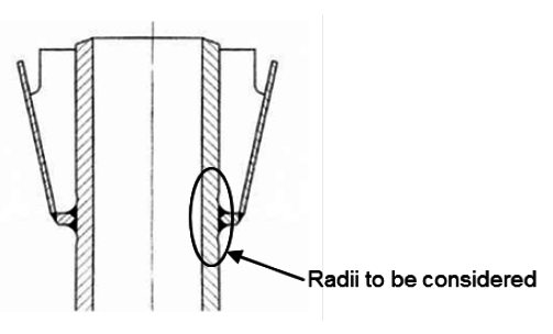
Figure 6.7.4 Rudder trunk fillet shoulder radii
7.5.7 The scantlings of the trunk are to be as follows:
- the equivalent stress due to bending and shear is not exceed 0,35σ,
- the bending stress, σb of fabricated rudder trunks
is to be less than

For calculation of bending stress, σb the span to be
considered is the distance between the mid-height of the lower rudder stock bearing
and the point where the trunk is clamped into the shell or the bottom of the
skeg.
7.6 Shaft bossing
7.6.1 Where
the propeller shafting is enclosed in bossings extending back to the
bearings supporting the propellers, the aft end of the bossings and
the bearings are to be supported by substantially constructed boss
end castings or fabrications. These are to be designed to transmit
the loading from the shafting efficiently into the ship's internal
structure.
7.6.2 The
length of the shaft bracket boss, l
b, is to
be sufficient to support the length of the required bearing. In general, l
b is not to be less than 4d
t,
where d
t is the Rule diameter of the screwshaft,
in mm, see
Pt 5, Ch 6, 3 Design.
Proposals for a reduction in the required length of the shaft bracket
boss will be considered in conjunction with details of the bearing
material, allowable bearing operating pressure and installation arrangements.
However, in no case is l
b to be less than
the greater of:
-
2d
t; or
-
that recommended by the bearing manufacturer;
or
-
that required to accommodate the aftermost
bearing and to allow the proper connection of the shaft bracket .
7.6.3 Where
the shaft and the shaft bracket boss are of the same material, the
thickness of the shaft bracket boss is not to be less than d
t/4. Where the shaft and the shaft bracket boss are of dissimilar
materials, the thickness of the boss, t
b,
is to be not less than:
|
t
b
|
= |
0,75d
t (f
1
1/3 –
0,667) mm
|
Note In no case is t
b to be taken as
less than 12 mm
where
|
d
t
|
= |
Rule diameter of the screwshaft in way of boss, in the appropriate
screwshaft material, in mm, see
Pt 5, Ch 6, 3 Design:
|
|
f
1
|
= |
sS/sB but not less than 0,825
|
|
sS
|
= |
ultimate
tensile strength of the shaft material, in N/mm2
|
|
sB
|
= |
ultimate
tensile strength of the boss material, in N/mm2.
|
7.6.4 Cast
steel supports are to be suitably radiused where they enter the main
hull to line up with the boss plating radius. Where the hull sections
are narrow, the two arms are generally to be connected to each other
within the ship. The arms are to be strengthened at intervals by webs.
7.6.5 Fabricated
supports are to be carefully designed to avoid or reduce the effect
of hard spots. Continuity of the arms into the ship is to be maintained,
and they are to be attached to substantial floor plates or other structure.
The connection of the arms to the bearing boss is to be by full penetration
welding.
7.6.6 The
scantlings of supports will be specially considered. In the case of
certain high powered ships, direct calculations may be required.
7.6.7 The
boss plating is generally to be radiused into the shell plating and
supported at the aft end by diaphragms at every frame. These diaphragms
are to be suitably stiffened and connected to floors or a suitable
arrangement of main and deep web frames. At the forward end, the main
frames may be shaped to fit the bossing, but deep webs are generally
to be fitted not more than four frame spaces apart.
7.6.8 The
region where the shafting enters the ship, and the bearing in way,
are to be adequately supported by floors or deep webs.

Figure 6.7.5 Propeller posts

Figure 6.7.6 Propeller boss
7.7 Shaft brackets
7.7.2 Where
the propeller shafting is exposed to the sea for some distance clear
of the main hull, it is generally to be supported adjacent to the
propeller by independent brackets having two arms. In very small ships,
the use of single arm brackets will be specially considered.
7.7.3 Fabricated
brackets are to be designed to avoid or reduce the effect of hard
spots and ensure a satisfactory connection to the hull structure.
The connection of the arms to the bearing boss is to be by full penetration
welding.
7.7.4 Where
bracket arms are carried through the shell plating, they are to be
attached to floors or girders of increased thickness. The shell plating
is to be increased in thickness and connected to the arms by full
penetration welding.
7.7.5 In the
case of certain high powered ships, direct calculations may be required
and scantlings of shaft brackets will be specially considered.
7.7.6 The
region where the shafting enters the ship, and the bearing in way,
is to be adequately supported by floors or deep webs.

Figure 6.7.7 Rudder axle

Figure 6.7.8 Rudder post for twin screw ships
7.8 Double arm shaft brackets (‘A’ – brackets)
7.8.1 The
angle between the arms for double arm shaft brackets is generally
to be not less than 50°. Proposals for the angle between the arms
to be less than 50° will be specially considered with supporting
calculations to be submitted by the designers.
7.8.2 The
arms of double arm shaft brackets are to have a section modulus, Zxx, of not less than that determined from the formula:
Where
|
n
|
= |
the
minimum thickness, in cm, of a hydrofoil section obtained from: |
|
n
|
= |

|
|
d
up
|
= |
the Rule diameter for an unprotected screwshaft, in mm, or by the
applicable Ice Class Rules, see
Pt 8, Ch 2, 7.8 Screwshafts, obtained from:

|
|
f
|
= |

|
|
σu
|
= |
ultimate
tensile strength of arm material, in N/mm2.
|

Figure 6.7.9 Double arm shaft bracket
7.9 Propeller hull clearances
|