
Section
3 Fixed and steering nozzles
3.1 General
3.1.1 The requirements given in this Section are applicable to fixed and
steering nozzles with an inner diameter of not greater than 5 metres.
3.1.3 Suitable arrangements are to be provided to prevent the steering nozzle
from lifting.
3.1.4 Effective means are to be provided for supporting the weight of the
nozzle. The hull structure, in way of the nozzle supports, is to be suitably
strengthened.
3.2 Design pressure
3.2.1 The design pressure for propeller nozzles, in kN/m 2, is to be
determined as follows:
|
Pd |
= |
czPd0 |
|
Pd0 |
= |
9+0,0025Nδp for NN ≤
63 |
|
Pd0 |
= |
13+0,002Nδp for 63 < NN ≤
200 |
|
Pd0 |
= |
εcf for NN > 200 for NN > 200 |
where
|
NN |
= |
is the nozzle numeral |
| = |
0,01Nδp |
|
N |
= |
is the maximum shaft power in kW |
|
Ap |
= |
is the propeller disc area, in m2, taken equal
to: |
| = |
|
|
δp |
= |
is the propeller diameter in m |
|
ε |
= |
is a factor obtained from the following
formula:
|
|
cz |
= |
is a coefficient taken equal to: |
| = |
cz = 1,0 in Zone 2 (propeller zone) |
| = |
cz = 0,5 in Zone 1 |
See also
Figure 13.3.1 Nozzle construction
|
cf |
= |
is a coefficient taken equal to: |
| = |
cf = 1,0 for fixed nozzles |
| = |
cf = 1,25 for steering nozzles |
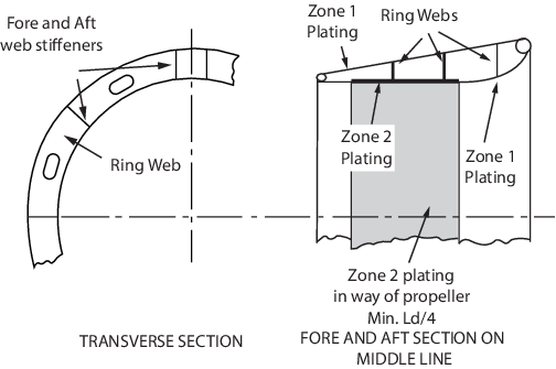
Figure 13.3.1 Nozzle construction
3.3 Nozzle scantlings
3.3.1 The scantlings of propeller nozzles are to be not less than required by
Table 13.3.1 Nozzle construction.
Table 13.3.1 Nozzle construction
| Item
|
Requirement
|
| (1) Nozzle plating
|
 but not less than 7,5 mm but not less than 7,5 mm
|
| (2) Ring webs and web stiffeners
|
Not less than the attached nozzle plating
in way of Zone 1
|
| (3) Webs in way of headbox and pintle
support structure
|
 mm mm
|
| (4) Section modulus of nozzle profile about
its neutral axis
|
 cm3 cm3
|
| Symbols
|
| Pd = nozzle design pressure, in
kN/m2, see
Pt 3, Ch 13, 3.2 Design pressure
|
| t =
thickness of nozzle plating, in mm
|
| tw = thickness of web plating, in mm
|
| s =
spacing of web rings, in m
|
| k = material factor, as defined in Pt 3, Ch 13, 1.2 General symbols
|
tk = corrosion thickness, to be taken as:
- tk = 2,5 in general
- tk = 1,5 for fresh water
environments
- tk = 0 for stainless
steel
|
| δ p
= propeller diameter, in m
|
| Ld = nozzle length, in m
|
n =
coefficient taken equal to:
- n = 1,0 for steering nozzles
- n = 0,7 for fixed nozzles
|
| V is as
defined in Pt 3, Ch 1, 6.1 Principal particulars
|
3.3.2 The Zone 2 nozzle plating is to be carried well forward and aft of the
propeller tips with due allowance being made on steering nozzles for the rotation of
the nozzle in relation to the propeller, and is to extend at least
0,25Ld in length.
3.3.3 Fore and aft web stiffeners are to be fitted between the inner and outer
skins of the nozzle. Both sides of the headbox and pintle support structure, are to
be connected to fore and aft webs of increased thickness.
3.3.4 The adjacent ring webs fore and aft of those connected to the headbox
and pintle support structure are to be of a similar thickness to the ring webs
connected to the headbox and pintle support structure.
3.3.5 Local stiffening is to be fitted in way of the top and bottom supports
which are to be integrated with the web stiffeners and ring webs. Continuity of
bending strength is to be maintained in these regions.
3.3.6 The plating thickness of attached fins is to be not less than the Zone 1
nozzle plating thickness. Solid fins should be not less than 25 mm thick.
3.4 Nozzle stock
3.4.1 The requirements for the nozzle stock are to be derived, in accordance
with Pt 3, Ch 13, 2.10 Rudder stock scantlings, using the
lateral nozzle force and maximum nozzle torque obtained in this sub-Section.
3.4.2 The lateral nozzle force, CR, at the centre of pressure is to be
determined as follows:
where
|
Pd |
= |
nozzle design pressure in Zone 2, in kN/m2 |
|
At |
= |
total projected area of nozzle and supporting structure, in
m2 |
|
At |
= |
An + Af + As |
where
|
An |
= |
projected area of nozzle, in m2, to be taken as
1,57δpLd |
|
Af |
= |
projected area of nozzle flap, in m2 |
|
As |
= |
projected area of support structure in the longitudinal plane, in
m2 |
where δp and Ld are defined in Table 13.3.1 Nozzle construction.
3.4.3 The maximum nozzle torque, QR, is to be determined as follows:
where
|
r |
= |
distance from the centre of pressure to the stock, in m, to be
taken as:
c(ɑ-k1)
|
|
c |
= |
nozzle length plus the length of the nozzle flap if present |
|
ɑ |
= |
relative centre of pressure along the nozzle length, to be taken as: |
|
ɑ |
= |
0,25 for fixed nozzles |
|
ɑ |
= |
0, 33 for steering nozzles |
|
k1 |
= |
ratio of the nozzle area forward of the stock centreline to the combined
area of the nozzle and flap
|
A1 is the portion of the projected nozzle area located
forward of the stock centreline, see also
Figure 13.3.2 Nozzle geometry
CR, An and Af are
given in Pt 3, Ch 13, 3.4 Nozzle stock 3.4.2.
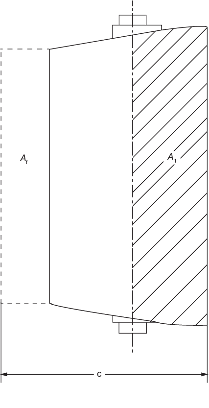
Figure 13.3.2 Nozzle geometry
3.5 Nozzle headbox
3.5.1 The section modulus of the headbox, Z, about the longitudinal axis
is to be not less than:
|
Z |
= |
0,143PdAtDh ×
102 cm3 |
where
|
Pd |
= |
nozzle design pressure in Zone 2, in kN/m2 |
|
DH |
= |
 |
3.5.2 Plans detailing the integration of the headbox into the sternframe are to be
submitted.
3.6 Ancillary items
3.6.1 Requirements for ancillary items such as bearings, couplings, pintles,
etc. are given in Pt 3, Ch 13, 2 Rudders.
3.7 Welding
3.7.1 Double continuous welds are to be used as far as practicable for the
connection between the inner and outer nozzle plating and the internal stiffening
rings and webs. Slot welding is not permitted for the inner nozzle plating.
3.8 Azimuth thrusters
|