
Section
8 Determination of forces for container securing arrangements
8.1 General
8.1.1 The forces acting in the securing system are to be determined for each
loading condition and associated set of motions of the ship.
8.1.2 The
following forces are to be taken into account:
- Static gravity forces.
- Inertial forces generated by the ship motions in a seaway.
- Wind forces.
- Forces imposed by the securing arrangements.
- Wave impact forces and effects of consequential hull girder whipping.
8.1.3 Forces
due to pre-tensioning the securing devices need not, in general, be
included in the calculation, provided that they do not exceed 5 kN
in any one item. Special consideration will be given to cases where
forces obtained from pre-stressing are an integral part of the design
of the system.
8.1.4 Although the operation of anti-roll devices or other systems may improve the behaviour
of the ship in a seaway, the effect of such devices is not normally to be taken into
account to reduce the determination of the forces for container securing arrangements.
Where the reliability of such systems can be demonstrated, special consideration of the
roll motions will be given. Supporting documentation to demonstrate the effectiveness of
an anti-rolling system should identify the redundancy incorporated in the control system
and details of actual measurements from the ship over a period of time, including route
and season of operation.
8.2 Ship motion, wind and green sea forces acting on containers
8.2.1 The
forces acting on each container due to gravity, ship motion accelerations,
ship rolling and pitching angles and wind forces and green sea forces
are to be calculated as follows.
8.2.2 The equations for ship motion accelerations and other motion parameters are
given in Pt 3, Ch 14, 1.7 Symbols and definitions. These are to be used for the calculation of accelerations to
derive the forces for the container securing arrangements. Alternatively, the ship
motion values may be derived by direct calculation methods using the same principles as
those used to derive the Rule equations. The formulae in Pt 3, Ch 14, 1.7 Symbols and definitions are
applicable to container ships. Values for other ship types will be specially
considered.
8.2.3 The
following six Motion Cases (MCs) are to be considered:
|
|
MC1:
|
Head sea case that maximises vertical
acceleration
|
|
|
MC2:
|
Beam sea case that maximises roll
motion
|
|
|
MC3:
|
Oblique sea case that maximises pitch
acceleration
|
|
|
MC4:
|
Oblique sea case with forward speed
that maximises roll motion
|
|
|
MC5:
|
Oblique sea case that maximises
combined transverse and vertical accelerations
|
|
|
MC6:
|
Beam sea case that maximises heave
acceleration
|
Each Motion Case comprises 2 Motion Combination Factor (MCF) sets. Each MCF
set represents an Equivalent Design Wave (EDW) that generates response values equivalent
to the long-term response values of the critical load components for ship motion forces
acting on containers. The Motion Combination Factors are given in Table 14.8.3 Motion Combination Factors
(MCFs).
8.2.4 The individual force components for each Motion Case due to gravity, ship
motions, wind and green seas acting on a container i are to be determined as
follows, see
Figure 14.1.1 Diagrammatic representation of
symbols and Table 14.9.1 Acceleration force application:
|
H
Di
|
= |
force acting on container i in kN in transverse direction
parallel to deck, positive to port |
|
J
Di
|
= |
force acting on container i in kN in longitudinal direction
parallel to deck, positive forward |
|
P
Di
|
= |
force acting on container i in kN in vertical direction
normal to deck, positive upward |
|
Q
Di
|
= |
wind force acting on exposed container i in kN in transverse
direction parallel to deck, positive to port |
| = |
Q
DSi
Q
DMi |
where:
|
QDMi |
= |
wind force magnitude acting on exposed container i in kN in transverse
direction parallel to deck |
| = |

where:
Croll wind force coefficient to include effect of roll
angle
|
|
= |
 |
ρ a density of air in kg/m 3 is to
be taken as
CZ wind force height distribution
coefficient
|
|
= |
 |
Vwh mean wind speed over the stack in
m/s
|
|
= |
 |
ztc height above moulded draught,
Tc, of the top of the highest container in the stack under
consideration, in m
zbc height above
moulded draught, Tc, of the underside of the stack under
consideration, in m
zci height above
moulded draught, Tc, of the centre of the side wall of
container i, in m
Cwh wind heading
coefficient, given in Table 14.8.1 Wind heading coefficient C
wh
CyG transverse acceleration motion combination factor
CyG, given in Table 14.8.3 Motion Combination Factors
(MCFs)
Other symbols are defined in Pt 3, Ch 14, 1.7 Symbols and definitions.
|
|
QDSi |
= |
Wind force direction coefficient |
| = |
-1 if HDi ≤ 0 kN |
| = |
1 if HDi > 0 kN |
|
H
Gi
|
= |
green sea force acting on container i, in kN in transverse
direction parallel to deck, positive to port |
|
|
= |
–b c
i
P
gs for port side exposed containers |
|
|
= |
b c
i
P
gs for starboard side exposed containers |
Note 1. HGi is only to be
applied when HGi will increase the transverse force
HDi.
|
J
Gi
|
= |
green sea force acting on container i, in kN in longitudinal
direction parallel to deck, positive forward |
Note 1. JGi is only to be
applied when JGi will increase the longitudinal force
JDi.
|
P
Gi
|
= |
green sea force acting on container i, in kN in the upwards
direction normal to deck |
Note 1. PGi is only to be
applied when the vertical acceleration az > -9,81 m/s2
(downward acceleration less than gravitational acceleration).
where
Table 14.8.1 Wind heading coefficient C
wh
|
|
Wind
heading coefficient C
wh
|
Motion
case
see Note 1
|
Only applied to
the
exposed side walls of containers as defined in Pt 3, Ch 14, 8.2 Ship motion, wind and green sea forces acting on containers 8.2.7
and Pt 3, Ch 14, 8.2 Ship motion, wind and green sea forces acting on containers 8.2.8
|
| MC1,
see Note 2
|
0
|
| MC2
|
1,00
|
| MC3
|
0,866
|
| MC4
|
0,866
|
| MC5
|
0,866
|
| MC6
|
1,00
|
Note
2. No wind loads are to be applied to
Motion Case MC1.
|
8.2.5 The
total instantaneous acceleration values acting on container i,
including the static gravitational term, are to be taken as:
where the Motion Combination Factors C
xS, C
xP, C
xG, C
yS, C
yR, C
yG, C
zH, C
zR and C
zP for each Motion Case are given in Table 14.8.3 Motion Combination Factors
(MCFs).
8.2.7 Wind forces are to be applied to containers in inboard stacks if the centre
of the windward side wall of the container is above the wind shear line, see
Figure 14.8.1 Application of wind forces. The wind shear line is to
be taken at an angle of 35 degrees to the horizontal and passing through upper deck at
side, the upper outer edge of the hatch cover or the top corner of the uppermost
container of any windward stack, as applicable, see
Figure 14.8.1 Application of wind forces. The roll angle is to be
ignored in the assessment of the wind shear line. The wind force is to be derived in
accordance with Pt 3, Ch 14, 8.2 Ship motion, wind and green sea forces acting on containers 8.2.4
but see also
Pt 3, Ch 14, 8.2 Ship motion, wind and green sea forces acting on containers 8.2.8.
- Hence wind forces are to be applied to containers in inboard stacks
if:
 - Where:
- zci is the vertical position of the centre of the
windward side wall of container i of the stack under consideration
- yws is the transverse position of the windward
upper deck at side, the upper outer edge of the hatch cover or the top corner of
the uppermost container of the stacks windward of the stack under consideration as
applicable
- zws is the vertical position of the windward upper
deck at side, the upper outer edge of the hatch cover or the top corner of the
uppermost container of the stacks windward of the stack under consideration as
applicable
- yci is the transverse position of the centre of
the windward side wall of container i of the stack under consideration
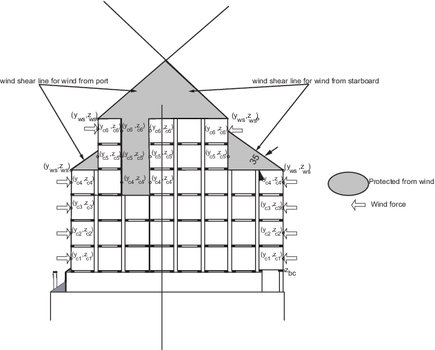
Figure 14.8.1 Application of wind forces
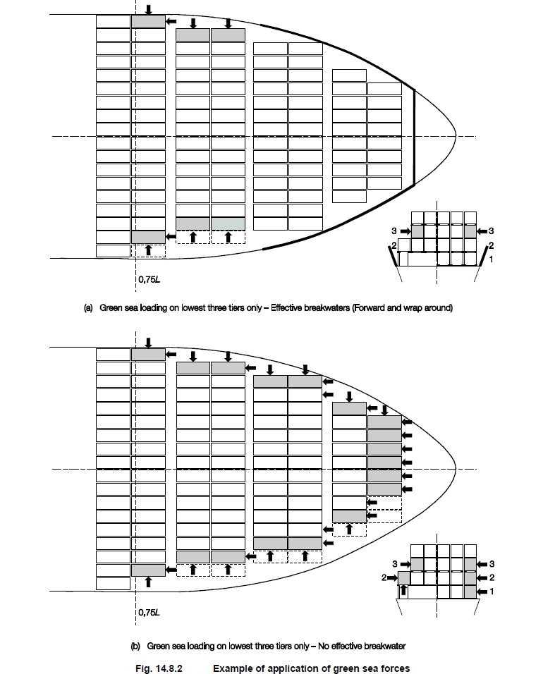
Figure 14.8.2 Example of application of green
sea forces
8.2.8 A container is considered protected from wind in the transverse direction
or from green sea loads in the longitudinal or transverse direction if an effective
breakwater or similar extends above mid height of the container.
8.2.9 A container is considered partially protected from wind if an outboard container
partially shields an inboard container as follows:
- An outboard 40ft container is considered to fully protect a longer inboard
container.
- An outboard 20ft container is considered to partially protect a
longer inboard container from wind. In this case the full wind force is to be
applied over the exposed portion of the longer inboard container when the exposed
length is more than 3m. The resulting wind force is to be applied solely to the
end wall of the exposed portion.
8.2.10 A container is considered protected from green sea loads in the vertical direction
if:
- the underside is less than 0,5 m above the hatch cover or deck; or
- an effective breakwater or similar extends above the bottom of the
container.
8.2.12 The
green sea pressure is given by:
for L >100
|
P
gs
|
= |
C
G1
L
2 + C
G2
L + C
G3 kN/m2 but
not less than 0
|
for L ≤ 100, P
gs is
to be taken as:
where
C
G1, C
G2, C
G3 are defined in Table 14.8.2 Green sea pressure
coefficients
Proposals
to use other values for green sea forces will be specially considered
Table 14.8.2 Green sea pressure
coefficients
|
|
C
G1
|
C
G2
|
C
G3
|
| Tier 1
|
–0,000017
|
0,0035
|
1,32
|
| Tier 2
|
–0,000020
|
0,0040
|
0,80
|
| Tier 3
|
–0,000023
|
0,0045
|
0,28
|
Table 14.8.3 Motion Combination Factors
(MCFs)
|
|
|
|
Longitudinal acceleration
|
Transverse acceleration
|
Vertical acceleration
|
Motion
Case
|
Heading
|
MCF
|
a-surge
|
a-pitch
|
g*sin ψ
|
a-sway
|
a-roll
|
g*sin φ
|
a-heave
|
a-roll
|
a-pitch
|
|
|
|
|
C
xS
|
C
xP
|
C
xG
|
C
yS
|
C
yR
|
C
yG
|
C
zH
|
C
zR
|
C
zP
|
| MC1
|
Head
|
HS_1
|
–0,69
|
1,00
|
–0,85
|
0,00
|
0,00
|
0,00
|
–0,18
|
0,00
|
1,00
|
| HS_2
|
0,69
|
–1,00
|
0,85
|
0,00
|
0,00
|
0,00
|
0,18
|
0,00
|
–1,00
|
| MC2
|
Beam
|
BS1_1
|
0,00
|
0,00
|
0,00
|
–0,09
|
0,66
|
–0,66
|
0,14
|
0,66
|
0,00
|
| BS1_2
|
0,00
|
0,00
|
0,00
|
0,09
|
–0,66
|
0,66
|
–0,14
|
–0,66
|
0,00
|
| MC3
|
Oblique
|
OS1_1
|
–0,43
|
1,00
|
–0,86
|
–0,28
|
–0,22
|
0,05
|
–0,29
|
–0,22
|
1,00
|
| OS1_2
|
0,43
|
–1,00
|
0,86
|
0,28
|
0,22
|
–0,05
|
0,29
|
0,22
|
–1,00
|
| MC4
|
Oblique
|
OS2_1
|
0,00
|
0,00
|
0,00
|
–0,02
|
1,00
|
–1,00
|
0,00
|
1,00
|
0,00
|
| OS2_2
|
0,00
|
0,00
|
0,00
|
0,02
|
–1,00
|
1,00
|
0,00
|
–1,00
|
0,00
|
| MC5
|
Oblique
|
OS3_1
|
0,62
|
–0,46
|
0,65
|
0,96
|
–0,36
|
0,12
|
0,11
|
–0,36
|
–0,46
|
| OS3_2
|
–0,62
|
0,46
|
–0,65
|
–0,96
|
0,36
|
–0,12
|
–0,11
|
0,36
|
0,46
|
| MC6
|
Beam
|
BS2_1
|
–0,07
|
–0,05
|
0,02
|
0,62
|
0,12
|
–0,01
|
1,00
|
0,12
|
–0,05
|
| BS2_2
|
0,07
|
0,05
|
–0,02
|
–0,62
|
–0,12
|
0,01
|
–1,00
|
–0,12
|
0,05
|
|