
Section
9 Strength of container securing arrangements
9.1 General
9.1.1 The securing system is to be designed on the basis of the most severe
combination of the forces specified in Pt 3, Ch 14, 8 Determination of forces for container securing arrangements in such a manner that the resultant forces on the containers
and securing devices are within allowable limits., the forces are to be calculated for
the most severe condition applicable to each arrangement.
9.1.4 The container orientation is to follow the cargo securing manual, however, if unknown
the container door end is assumed to face aft.
9.1.6 For containers that are stowed in the fore and aft direction, it is sufficient to
calculate the forces in the lashing rods based on assessment of the transverse and
vertical loads acting on the containers. The vertical forces in the corner posts are to
include the effects of transverse and longitudinal loads acting on the containers.
9.1.7 For containers that are stowed athwartships, the transverse, longitudinal and vertical
loads acting on the containers will need to be taken into account in calculating the
forces in the lashing rods. The vertical forces in the corner posts are to include the
effects of transverse and longitudinal loads acting on the containers. The approach to
be adopted should be agreed with Lloyd’s Register.
9.2 Forces applied to each container
9.2.1 Forces due to acceleration, green water and wind in accordance with Pt 3, Ch 14, 8 Determination of forces for container securing arrangements,
are to be applied as follows:
- Acceleration forces are to be calculated about the centre of gravity
of the container.
- Vertical acceleration forces and self-weight are to be distributed to
the four bottom corner castings.
- Vertical, transverse and longitudinal green sea loads act uniformly
over the exposed panel of the container.
- Wind loads act uniformly over the exposed panel of the
container.
9.2.2 Table 14.9.1 Acceleration force application shows a method to apply
the forces to a container, assuming centre of gravity of the container is to be taken as
half way along its length, midway between the port and starboard wall, and
cVGGi off the container floor.
Table 14.9.1 Acceleration force application
9.3 Analysis of the container stack
9.3.1 LR’s Guidance Notes for Calculation Procedure of Container Stack
Analysis describes a methodology that complies with these requirements.
9.3.2 The application of ship motion and environmental loads will induce forces in the
container boxes and lashing devices which result in distortion of the container
stack. The key structural items resisting this distortion are as follows:
- The shear stiffness of the container end and side panels;
- The axial stiffness of the container corner posts;
- The stiffness of the lashing devices, including lashing bridge structure,
when present;
- Under certain conditions and lashing arrangements, the twistlock can
experience lifting forces which result in increased stack distortion.
All these aspects need to be considered in the stack analysis.
9.3.3 The forces in the containers, twistlocks and lashing devices are calculated from the
stack distortion. Using the forces applied to the stack in 9.2 Forces applied to
each container and the stiffness of the stack, the overall stack deformation
is calculated using the standard force-displacement equations. Non-linearity of the
system as a consequence of twistlock separation and lashing rods is to be considered
in evaluating the deformation. The inclusion of twistlock separation and corner post
stiffness results in an increase in the loads in the lashing devices. The inclusion
of a lashing bridge structure significantly affects the support a lashing device can
provide for the stack and hence must be considered.
9.3.4 The overall distortion behaviour of a container is a combination of its
shear stiffness and corner post stiffness. A container is to be modelled as a
combination of shear only panels representing the walls, and rod elements
representing the corner posts and horizontal frame structures. The shear stiffness
of the container walls is to be taken as specified in Table 14.9.2 Shear spring stiffness of container walls. The area
and Young’s Modulus of the corner posts and horizontal frame members is to be taken
as specified in Table 14.9.3 Container post properties.
Table 14.9.2 Shear spring stiffness of container walls
| Container
height
|
Door
end
kN/mm
|
Closed
end
kN/mm
|
Side
wall
kN/mm
|
| 2,438 m (8
ft)
|
3,7
|
16,7
|
6,1
|
| 2,591 m (8
ft 6 in)
|
3,5
|
15,4
|
5,7
|
| 2,743 m (9
ft)
|
3,3
|
14,3
|
5,4
|
| 2,896 m (9
ft 6 in)
|
3,2
|
13,3
|
5,1
|
Table 14.9.3 Container post properties
| Property
|
Corner post
properties
|
Horizontal
post properties
|
| Effective
Area
|
3800
mm2
|
2000
mm2
|
| Young’s
Modulus
|
206
kN/mm2
|
206
kN/mm2
|
9.3.5 Lashing devices are to be taken into account and their properties modelled to capture
their behaviour. These include but are not limited to lashing rods and shore
devices.
9.3.6 Lashing rods are to be modelled using tension only rod elements.
Elongation may be determined by reference to an effective cross-sectional area and
an effective modulus of elasticity of the lashing (allowance for straightening and
stretching), which in the absence of actual test values,is to be taken as specified
in Table 14.9.4 Effective modulus of
elasticity of lashing devices.
9.3.7 Lashing rod stiffness, kLr, in kN/mm may be derived as
follows:
where
9.3.8 For external and internal para-lash arrangements, each lashing rod is to be
individually modelled and connected to the relevant container casting.
9.3.9 Other lashing rod arrangements, e.g. an internal para-lash with load
equaliser arrangements, will need to be specially considered.
Table 14.9.4 Effective modulus of
elasticity of lashing devices
| Lashing equipment
|
Effective modulus of elasticity
|
| Steel rod lashings of hook type, including turnbuckle
|
98 kN/mm2
|
| Short (one tier) steel rod lashings (knob type), including
turnbuckle and lashing eyes
|
140 kN/mm2
|
| Long (two tier) steel rod lashings (knob type), including
turnbuckle and lashing eyes
|
175 kN/mm2
|
| Steel wire rope lashings
|
90 kN/mm2
|
| Steel chain lashings (based on the nominal diameter of the
chain)
|
80 kN/mm2
|
| Adjustable tension/compression buttress
|
120 kN/mm2
|
| Aluminium or other materials
|
To be specially considered
|
9.3.10 Any other element introducing flexibility into the structure between the
lashing point and the base of the container stack is to be evaluated and taken into
account. Examples of this could be flexibility of the lashing bridge, sliding of a
hatch cover or torsional deformations of the hull.
9.3.11 Where lashing devices are attached to a lashing bridge, the lashing bridge transverse
stiffness is to be taken into account and may be modelled as an additional rod
element. For lashing bridge designs with multiple lashing platforms, a lashing
bridge rod element is required for each platform. All the lashing bridge rod
elements are to be connected in series. The bottom of the lashing bridge can be
assumed to be rigidly fixed.
A default Rule stiffness for each platform of the lashing bridge is to be modelled
with a rod with a transverse spring stiffness ( Klbyi) calculated
from the following:
where
Hlbi is the height of lashing bridge tier i,
taken in m, see
Figure 14.9.1 Lashing bridge transverse spring stiffness
Clb is the lashing bridge stiffness coefficient, taken
as 50 for single elevated lashing bridge tiers at the outer stack, see
Figure 14.9.1 Lashing bridge transverse spring stiffness, and 70 otherwise.
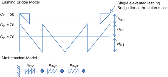
Figure 14.9.1 Lashing bridge transverse spring stiffness
9.3.12 For lashing bridge designs having a higher transverse stiffness than the
default stiffness value of 70/Hlbi, in kN/mm, the stack analysis
can be based on the actual stiffness value determined in accordance with the
ShipRight ADP Procedure for the Assessment of Container Ship Lashing Bridge
Structures.
9.3.13 Alternative proposals for the transverse stiffness of the lashing bridge will be
individually considered.
9.3.14 Inherent in the twistlock design is a need for play in order to be able
to fit the device. This play allows easy installation of the twistlocks, but this
also means that vertical lifting of the top container occurs before the twistlock
comes in to tension. Twistlocks therefore have three states, see
Table 14.9.5 Twistlock separation and states. This vertical
lifting distance is referred to as twistlock separation. If this separation occurs
then it can significantly increase the transverse stack deformation and the forces
in the lashing devices. The assessment of the effects of twistlock separation is
particularly critical for external lashing arrangements.
Table 14.9.5 Twistlock separation and states
| State
|
Figure
|
Description
|
| Twistlock
closed
|
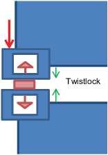
|
Twistlock
closed and in compression.
The distance between the container
castings is equal to the twistlock height.
|
| Twistlock
open
|
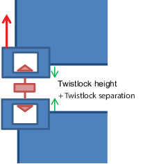
|
Twistlock
open and in tension.
The distance between the container castings
is equal to the twistlock height plus twistlock
separation.
|
| Twistlock
float
|
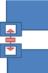
|
Float
condition with zero axial force.
The distance between the
container castings is in between closed and open
state.
|
9.3.15 Twistlock separation and height is to be provided by the lashing manufacturer. If
this information is not available, the twistlock flange height is to be taken as 28
mm and the twistlock separation as 18 mm for FATs, SATs and manual twistlocks.
9.3.16 In the analysis of container stacks, it may be assumed that shear deformation of
twistlocks can be ignored.
9.3.17 Initial displacement of containers due to tolerances in container fittings will be
considered in conjunction with the stowage arrangement proposed. Generally, initial
displacement may be neglected in calculation procedures for conventional
stowages.
9.4 Allowable forces on containers, fittings and lashing devices
9.4.2 The vertical force in the corner post is to be calculated from the
compression of the post plus the vertical force due to shear in the end wall acting
on the post. The maximum compressive force in each corner post of the container must
not exceed the vertical forces at each top corner casting and in each corner post
specified in Table 14.9.6 Allowable forces in containers
in stacks with the same base size.
9.4.3 The maximum vertical compressive force in the twistlock is not to be greater than the
allowable vertical forces at each bottom corner casting, compression and the maximum
vertical tensile force in the twistlock is not to be greater than the allowable
vertical corner pull-out force at each bottom corner casting.
9.4.4 The twistlock tensile load is to be less than the safe working load.
9.4.5 The forces and force components in the lashing devices must not be greater than the
allowable lashing forces on the corner castings and the safe working load of the
lashing device.
9.4.12 When Fully Automatic Twistlocks (FATs) are used, it is to be ensured that at least
one of the port and starboard FATs at each end is in compression. This is to ensure
that the FATs would not become disengaged.
Table 14.9.6 Allowable forces in containers
in stacks with the same base size
|
|
20 ft
|
40
ft
|
45 ft
|
|
|
in kN
|
| Resultant horizontal force from
lashing on lower container casting acting parallel to the end
face
|
225
|
225
|
225
|
| Resultant vertical force from
lashing on lower container casting acting parallel to the end or
side face
|
250
|
250
|
250
|
| Resultant force from lashing
on lower container casting acting parallel to the end or side
face
|
300
|
300
|
300
|
| Resultant vertical force from
lashing on upper container casting acting parallel to the end or
side face
|
125
|
125
|
125
|
| Resultant force from lashing
on upper container casting acting parallel to the end or side
face
|
188
|
188
|
188
|
| Racking force on container
end
|
150
|
150
|
150
|
| Racking force on container
side
|
200
|
200
|
200
|
| Vertical forces at each upper
top corner casting, tension
|
250
|
250
|
250
|
| Vertical forces at each lower
bottom corner casting, tension
|
250
|
250
|
250
|
| Vertical forces in each corner
post, tension
|
375
|
375
|
375
|
| Vertical forces at each top
corner casting and in each corner post, compression
|
848
see Note 2
|
848
see Note 2
|
942
|
| Vertical forces at each bottom
corner casting, compression
|
848 + (1,8Rg/4)
see Note 3
|
848 + (1,8Rg/4)
see Note 3
|
942 + (1,8Rg)/4
|
| Transverse forces acting at
the level of and parallel to the top face, tension or compression,
see Note 2
|
340
|
340
|
340
|
| Transverse forces acting at the
level of and parallel to the bottom face, tension or compression,
see Note 1
|
500
|
500
|
500
|
Note
1. Where a buttress supports
the stack at an intermediate level, the total transverse
force in the containers at the level is not to exceed the
sum of the appropriate top and bottom forces.
|
|
Note 2. Containers
that are certified to comply with ISO 1496-1:1990 including
Amendment 4 may have the top corner casting and post compression
increased to 942 kN.
|
|
Note 3. Containers that are certified to comply with ISO
1496-1:1990 including Amendment 4 may have the bottom corner
casting compression increased to 942 + (1,8Rg/4)
|
Table 14.9.7 Allowable compression forces for posts and corner castings of 40 ft and 45 ft
containers in mixed stacks
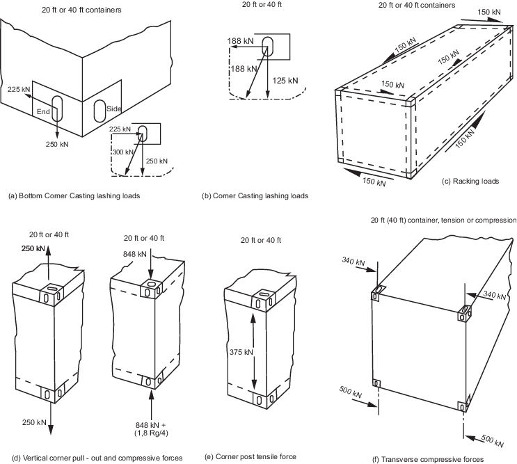
Figure 14.9.2 Allowable forces for 20 ft or 40 ft containers constructed to ISO 1496-1:1990
including Amendment Nos. 1, 2 and 3
|