
Section
7 Equipment Number
7.1 Calculation of Equipment Number
7.1.1 The equipment of anchors and chain cables specified in Pt 3, Ch 13, 7 Equipment is based on an `Equipment Number' which is to be calculated as
follows:

where
|
A
|
= |
area, in m2, in profile view of the hull, within the
Rule length of the vessel, and of superstructures and houses and funnels above
the summer load waterline, which are within the Rule length of the vessel, and
also having a breadth greater than  . The side projected area of the funnel is considered in
A when AFS is greater than zero. In this case, the
side projected area of the funnel should be calculated between the upper deck,
or notional deck line where there is local discontinuity in the upper deck, and
the effective height hF. . The side projected area of the funnel is considered in
A when AFS is greater than zero. In this case, the
side projected area of the funnel should be calculated between the upper deck,
or notional deck line where there is local discontinuity in the upper deck, and
the effective height hF.
See also
Pt 3, Ch 1, 7.1 Calculation of Equipment Number 7.1.3, Pt 3, Ch 1, 7.1 Calculation of Equipment Number 7.1.4 and Pt 3, Ch 1, 7.1 Calculation of Equipment Number 7.1.5.
|
|
B
|
= |
greatest moulded breadth, in metres. |
|
H
|
= |
effective height, in m, from the summer load waterline to the top
of the uppermost house.
|
|
a |
= |
vertical distance at hull side, in m, from the summer load waterline amidships
to the upper deck. |
|
hi
|
= |
height, in m, on the centreline of each tier of houses having a
breadth greater than  ; for the lowest tier, h1 is to
be measured at centreline from the upper deck or from a notional deck line
where there is local discontinuity in the upper deck, see
Figure 1.7.1 Computation of ‘H’
for an example. See also
Pt 3, Ch 1, 7.1 Calculation of Equipment Number 7.1.2, Pt 3, Ch 1, 7.1 Calculation of Equipment Number 7.1.3 and Pt 3, Ch 1, 7.1 Calculation of Equipment Number 7.1.4 ; for the lowest tier, h1 is to
be measured at centreline from the upper deck or from a notional deck line
where there is local discontinuity in the upper deck, see
Figure 1.7.1 Computation of ‘H’
for an example. See also
Pt 3, Ch 1, 7.1 Calculation of Equipment Number 7.1.2, Pt 3, Ch 1, 7.1 Calculation of Equipment Number 7.1.3 and Pt 3, Ch 1, 7.1 Calculation of Equipment Number 7.1.4
|
|
Δ |
= |
moulded displacement, in tonnes, to the summer load
waterline. |
|
Sfun |
= |
effective front projected area of the funnel, in m², defined as:
Sfun = AFS-
Sshield
See also
Pt 3, Ch 1, 7.1 Calculation of Equipment Number 7.1.4.
|
|
AFS |
= |
front projected area of the funnel, in m², calculated between the upper deck
at centreline, or notional deck line where there is local discontinuity in the
upper deck, and the effective height hF.
AFS is taken equal to zero if the funnel breadth is less
than or equal to  at all elevations along the funnel height. at all elevations along the funnel height. |
|
hF
|
= |
effective height of the funnel, in m, measured from the upper deck at
centreline, or notional deck line where there is local discontinuity in the
upper deck, and the top of the funnel. The top of the funnel may be taken at
the level where the funnel breadth reaches  . . |
|
Sshield |
= |
the section of front projected area AFS, in m²,
which is shielded by all deck houses having breadth greater than  . If there is more than one shielded section, then the
individual shielded sections i.e. Sshield1,
Sshield2 etc as shown in Figure 1.7.2 Computation of Sshield to be added together. To determine Sshield,
the deckhouse breadth is assumed B for all deck houses having breadth
greater than . If there is more than one shielded section, then the
individual shielded sections i.e. Sshield1,
Sshield2 etc as shown in Figure 1.7.2 Computation of Sshield to be added together. To determine Sshield,
the deckhouse breadth is assumed B for all deck houses having breadth
greater than  as shown for Sshield1,
Sshield2 in Figure 1.7.2 Computation of Sshield. as shown for Sshield1,
Sshield2 in Figure 1.7.2 Computation of Sshield. |
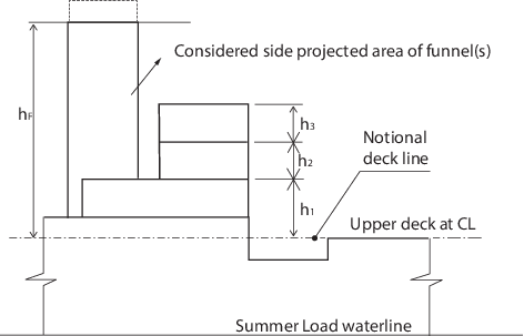
Figure 1.7.1 Computation of ‘H’
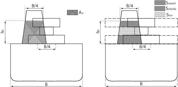
Figure 1.7.2 Computation of Sshield
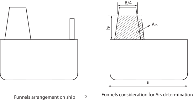
Figure 1.7.3 Computation of hF and AFS in the case of
multiple funnels
7.1.2 In the calculation of H, sheer and trim are to be ignored. Where
there is a local discontinuity in the upper deck, H is to be measured from a
notional deckline.
7.1.3 If a house having a breadth greater than  is above a house with a breadth of is above a house with a breadth of  or less, then the wide house is to be included, but the narrow house
ignored. or less, then the wide house is to be included, but the narrow house
ignored.
7.1.4 Screens and bulwarks more than 1,5 m in height are to be regarded as parts
of houses when determining H and A. Where a screen or bulwark is of
varying height, the portion to be included is to be that length the height of which
exceeds 1,5 m. The height of the hatch coamings and that of any deck cargo, such as
containers, may be disregarded when determining H and A.
7.1.5 When several funnels are fitted on the ship, the parameters mentioned in
Pt 3, Ch 1, 7.1 Calculation of Equipment Number 7.1.1 are to be taken as follows:
hF: effective height of the funnel, in m, measured from
the upper deck, or notional deck line where there is local discontinuity in the upper
deck, and the top of the highest funnel. The top of the highest funnel may be taken at
the level where the sum of each funnel breadth reaches  as shown in the Figure 1.7.3 Computation of hF and AFS in the case of
multiple funnels. When one funnel is fully or partially shielded by
another funnel, the shielded area shall be omitted in calculating the sum total breadth
of the funnels. as shown in the Figure 1.7.3 Computation of hF and AFS in the case of
multiple funnels. When one funnel is fully or partially shielded by
another funnel, the shielded area shall be omitted in calculating the sum total breadth
of the funnels.
AFS: sum of the front projected area of each funnel, in
m², calculated between the upper deck, or notional deck line where there is local
discontinuity in the upper deck, and the effective height hF.
AFS is to be taken equal to zero if the sum of each funnel breadth
is less than or equal to  at all elevations along the funnel’s height. When one funnel is fully
or partially shielded by another funnel, the shielded area shall be omitted. at all elevations along the funnel’s height. When one funnel is fully
or partially shielded by another funnel, the shielded area shall be omitted.
A: Side projected area, in m2, of the hull,
superstructures, houses and funnels above the summer load waterline which are within the
Rule length of the ship. The total side projected area of the funnels is to be
considered in the side projected area of the ship, A, when AFS
is greater than zero. The shielding effect of funnels in the transverse direction may be
considered in the total side projected area, i.e. when the side projected areas of two
or more funnels fully or partially overlap, the overlapped area needs only to be counted
once.
7.1.6 The Equipment Number for tugs is to be calculated as follows:
where
|
Δ, B and A
|
= |
are defined in Pt 3, Ch 1, 7.1 Calculation of Equipment Number 7.1.1
|
|
b
|
= |
breadth, in metres, of the widest superstructure or deckhouse on
each tier having a breadth greater than  |
|
f
|
= |
freeboard amidships, in metres, from the summer load waterline |
|
h
|
= |
the height, in metres, of each tier of superstructure or deckhouse
at side having a breadth of  or greater. In the calculation of h, sheer and trim are
to be ignored. or greater. In the calculation of h, sheer and trim are
to be ignored. |
7.1.7 In the case of dredgers having normal ship shape underwater hull, bucket
ladders and gallows are not to be included in the Equipment Number calculations. If the
dredger has an unusual underwater hull design or has a limited service area, the
anchoring equipment needs to be specially considered.
7.1.8 The Equipment Number formulae for anchoring equipment as given in this
Section are based on an assumed maximum current speed of 2,5 m/s, maximum wind speed of
25 m/s and a minimum scope of chain cable of 6, the scope being the ratio between length
of chain paid out and water depth. For ships with a Rule length, L, greater than 135 m,
the required anchoring equipment is also considered adequate for a maximum current speed
of 1,54 m/s, a maximum wind speed of 11 m/s and waves with maximum significant height of
2 m.
7.1.9 For sailing passenger ships, the equipment requirement is to be in accordance with the
letter and numeral two grades higher than that corresponding to the calculated Equipment
Numeral.
|