
Section
7 Equipment
7.1 General
7.1.3 Where
the Committee has agreed that anchoring and mooring equipment need
not be fitted in view of the particular service of the ship, the character
letter N will be assigned, see also
Pt 1, Ch 2, 2.2 Character symbols 2.2.2.
Table 13.7.1 Equipment requirements
| Ship type
|
Service
|
Required
equipment
|
| Cargo ships, bulk carriers,
tankers, ferries, dredgers, etc. (see
Pt 3, Ch 13, 1.1 Application 1.1.2)
|
Unrestricted
service
|
(1) The equipment is to be selected from the following sub-Sections as
appropriate, using NC
|
| Anchor and chain
cables
|
See
Table 13.7.2 Equipment - Bower anchors and
chain cables
|
| Mooring lines
|
See
Pt 3, Ch 13, 7.5 Mooring lines (Equipment Number ≤ 2000) or Pt 3, Ch 13, 7.6 Mooring lines (Equipment Number > 2000) as appropriate.
|
| Towing line
|
See
Pt 3, Ch 13, 7.8 Towline and towing arrangement
|
| Ferries
|
Certain restricted services, see
Pt 1, Ch 2, 2.3 Class notations (hull) 2.3.9
|
(2) As per
item (1), using NC and NA as
appropriate
|
|
Mass of bower anchor
|
NA = one grade below NC
|
| Chain cable length and
diameter
|
NA = one grade below NC
|
| Stream
anchor may be omitted
|
| Specified coastal service, see
Pt 1, Ch 2, 2.3 Class notations (hull) 2.3.8
|
(3) As per item (2), and
|
| Chain cables
|
Where L < 40 m, wire ropes may
be used in place of chain cables when the requirements specified under Pt 3, Ch 13, 7.4 Chain cables and chain locker 7.4.7 and Pt 3, Ch 13, 7.4 Chain cables and chain locker 7.4.9 are complied with.
|
| Where 40 m ≤ L ≤ 90 m, chain
cables may be replaced with wire rope of equal minimum breaking strength
when:
|
| (a) the requirements specified for
L < 40 m are complied with and
|
| (b) have a minimum mass per unit
length of 30% that of Grade U2 chain cable required by Table 13.7.2 Equipment - Bower anchors and
chain cables.
|
| Dredging and reclamation craft
|
Extended protected waters service, see
Pt 1, Ch 2, 2.3 Class notations (hull) 2.3.7
|
(4) As per item (1), using NC and NA as
appropriate
|
| NA = NC reduced by two grades,
except for stream anchors or mooring lines
|
| Stream anchor
|
– not required if ship fitted with
positioning spuds
|
| Protected waters service, see
Pt 1, Ch 2, 2.3 Class notations (hull) 2.3.6
|
(5) As per
item (1), using NC and NA as
appropriate
|
| Mass of bower
anchor
|
NA
= 0,5NC
|
| Chain cable
diameter
|
NA
= 0,5NC
|
| Bower
anchors
|
powered ships – two
anchors
|
| Bower
anchors
|
unpowered (manned) ships
– one anchor
|
| Chain cable
length
|
– greater of 2L m
or 10,0TD m, but need not exceed requirements for an
ordinary cargo ship with anchors of the same mass
|
| Mooring lines
|
– as required for
NC
|
| Wire ropes
|
– may be substituted for
chain cable on bower anchors if breaking strength ≥1,5 times that of the
chain cable
|
| Trawlers, stern trawlers, fishing vessels
|
Unrestricted service
|
(6) The equipment for fishing vessels is to be selected from Pt 3, Ch 13,
Table 13.7.4 Equipment for fishing vessels using
NC
|
| Chain cables
|
Where L < 40 m,
wire ropes (including those fitted to trawl winches) may be used in place of
chain cables when the requirements specified under Pt 3, Ch 13, 7.4 Chain cables and chain locker 7.4.7 and Pt 3, Ch 13, 7.4 Chain cables and chain locker 7.4.9 are complied with.
|
| Hawsers and
warps
|
– Sufficient in number
and strength for proper working of the ship
|
| Tugs
|
Unrestricted and restricted service
|
(7) As per item (1) using NC except as stated
below
|
| Stream anchor
|
– not required
|
| Towlines
|
– adequate for tug’s
maximum bollard pull with factor of safety ≥ 2,0
|
| Service restricted, see
Pt 1, Ch 2, 2.3 Class notations (hull) 2.3.7 to Pt 1, Ch 2, 2.3 Class notations (hull) 2.3.10
|
(8) As per item (1) using NC
|
| Mass of bower
anchor
|
reduced to correspond to
two Equipment Letters below that required for NC
|
| Chain cable
diameter
|
reduced to correspond to
two Equipment Letters below that required for NC
|
|
|
Anchor chains
|
As item (3) in this
Table
|
| Protected waters service, See
Pt 1, Ch 2, 2.3 Class notations (hull) 2.3.6
|
(9) As per item (1) using NA
|
| Mass of bower
anchor
|
NA =
0,5NC
|
| Chain cable
diameter
|
NA =
0,5NC
|
| Chain cable
length
|
= 0,5 times length
required by NA
|
| Where NC < 90, the requirements for anchors and chain
cable will be specially considered
|
| Anchor chains
|
As item (3) in this
Table
|
| Offshore supply ships
|
Unrestricted service
|
(10) As per item (1) using NC
|
| Chain cable length and
diameter
|
– increased to correspond
to two Equipment Letters above that required for NC. Need
not be applied for ships with DP(AAA), DP(AA) or DP(AM)
notations
|
| Manned barges and
pontoons
|
Service restricted,
see Pt 1, Pt 1, Ch 2, 2.3 Class notations (hull) 2.3.7 to Pt 1, Ch 2, 2.3 Class notations (hull) 2.3.10
|
(11) As per item (4) in this Table
|
| Unmanned barges and pontoons
|
Unrestricted service, or service restricted,see
Pt 1, Ch 2, 2.3 Class notations (hull) 2.3.7 to Pt 1, Ch 2, 2.3 Class notations (hull) 2.3.10TT
|
(12) As per item (1) using NC and NA as
appropriate
|
| Anchors
|
L < 30 m, no
anchor need be carried
|
| Anchors
|
L ≥ 30 m, one
anchor to be fitted
|
| Anchor cable length
|
– greater of 40 m or 2L
m
|
| (a) Unrestricted service:
|
| mass of anchors and chain cable diameters as for
NC
|
| (b) Protected water service, see
Pt 1, Ch 2, 2.3 Class notations (hull) 2.3.6: mass of anchors and chain cable diameters,
NA = 0,5NC
|
| (c) Service restriction, see
Pt 1, Ch 2, 2.3 Class notations (hull) 2.3.7 to Pt 1, Ch 2, 2.3 Class notations (hull) 2.3.10: mass of anchor and chain cable diameter,
NA reduced to correspond to two Equipment Letters below
NC
|
| Mooring lines
|
L < 65 m, two mooring
lines to be fitted
|
|
|
L ≥ 65 m, three mooring lines
to be fitted length of mooring lines to be the greater of 2L or 80 m,
but need not exceed that for manned ships Strength of each line to be that
required by NC Consideration will be given to proposals to omit anchoring
equipment in association with the assignment of the character figure 1,
See
Pt 1, Ch 2, 2.2 Character symbols. Where L < 65 m consideration will be
given to the omission of anchoring and mooring equipment, in which case the
character letter N will be assigned in the character of classification,
see
Pt 1, Ch 2, 2.2 Character symbols
|
| Symbols
|
| L = length of ship as defined in Pt 3, Ch 1, 6.1 Principal particulars
|
| NA = actual equipment number to be used,
if different from NC
|
| NC = calculated equipment number for ship
as required by Pt 3, Ch 1, 7.1 Calculation of Equipment Number
|
| TD = maximum depth at which ship is designed to
dredge, in metres
|
7.1.4 Where the ship is intended to perform its primary designed service function
only while it is anchored, moored, towed or linked, the character letter T will
be assigned, see also
Pt 1, Ch 2, 2.2 Character symbols 2.2.2.
7.1.5 For
classification purposes, the character figure 1, or either
of the character letters N or T, is to be
assigned.
7.1.6 The anchoring equipment required herewith is intended for temporary mooring of a ship
within a harbour or sheltered areas when the ship is awaiting berth, tide, etc. It is
designed to hold a ship only in good holding ground conditions to avoid dragging of the
anchor. In poor holding ground, the holding power of the anchors would be significantly
reduced.
7.1.7 It is assumed that under normal circumstances a ship uses only one bower anchor and
chain cable at a time.
7.1.8 All anchors and chain cables are to be tested at establishments and on machines
recognised by the Committee and under the supervision of LR’s Surveyors or other
Officers recognised by the Committee, and in accordance with Ch 10 Equipment for Mooring and Anchoring of the Rules for Materials.
7.1.9 Test certificates showing particulars of weights of anchors, or size and weight of cable
and of the test loads are applied to be furnished. These certificates are to be examined
by the Surveyors when the anchors and cables are placed on board the ship.
7.2 Anchors
7.2.1 Anchors
are to be of an approved design. The design of all anchor heads is
to be such as to minimise stress concentrations, and in particular,
the radii on all parts of cast anchor heads are to be as large as
possible, especially where there is considerable change of section.
7.2.2 Anchors
which must be specially laid the right way up, or which require the
fluke angle or profile to be adjusted for varying types of sea bed,
will not generally be approved for normal ship use, but may be accepted
for offshore units, floating cranes, etc. In such cases suitable tests
may be required.
7.2.3 The mass of each bower anchor given in Table 13.7.2 Equipment - Bower anchors and
chain cables is for anchors of equal mass.
The masses of individual anchors may vary by ± 7 per cent of the masses given in the
Table, provided that the total mass of the anchors is not less than would have been
required for anchors of equal mass.
7.2.4 The
mass of the head, including pins and fittings, of an ordinary stockless
anchor is to be not less than 60 per cent of the total mass of the
anchor.
7.2.5 When stocked bower or stream anchors are to be used, the mass excluding the
stock is to be not less than 80 per cent of the mass given in Table 13.7.2 Equipment - Bower anchors and
chain cables for ordinary stockless bower
anchors. The mass of the stock is to be 25 per cent of the total mass of the anchor,
including the shackle, etc. but excluding the stock.
7.2.6 It is recommended that anchor lashings, e.g. a ‘devil’s claw’, be fitted to hold the
anchor tight against the hull or the anchor pocket. Anchor lashings are to be designed
to resist at least a load corresponding to twice the anchor mass plus 10 m of cable
without exceeding 40 per cent of the yield strength of the material.
Table 13.7.2 Equipment - Bower anchors and
chain cables
| Equipment number
|
|
Stockless bower anchors
|
Stud link chain cables for bower anchors
|
|
|
|
|
|
|
|
Diameter, in mm
|
| Exceeding
|
Not
Exceeding
|
Equipment Letter
|
Number
|
Mass
of anchor, in kg
|
Total
length, in metres
|
Mild
steel (Grade 1 or U1)
|
Special quality steel (Grade U2)
|
Extra
special quality steel (Grade U3)
|
| 50
|
70
|
A
|
2
|
180
|
220
|
14
|
12,5
|
12,5
|
| 70
|
90
|
B
|
2
|
240
|
220
|
16
|
14
|
14
|
| 90
|
110
|
C
|
2
|
300
|
247,5
|
17,5
|
16
|
16
|
| 110
|
130
|
D
|
2
|
360
|
247,5
|
19
|
17,5
|
17,5
|
| 130
|
150
|
E
|
2
|
420
|
275
|
20,5
|
17,5
|
17,5
|
| 150
|
175
|
F
|
2
|
480
|
275
|
22
|
19
|
19
|
| 175
|
205
|
G
|
2
|
570
|
302,5
|
24
|
20,5
|
20,5
|
| 205
|
240
|
H
|
2
|
660
|
302,5
|
26
|
22
|
20,5
|
| 240
|
280
|
I
|
2
|
780
|
330
|
28
|
24
|
22
|
| 280
|
320
|
J
|
2
|
900
|
357,5
|
30
|
26
|
24
|
| 320
|
360
|
K
|
2
|
1020
|
357,5
|
32
|
28
|
24
|
| 360
|
400
|
L
|
2
|
1140
|
385
|
34
|
30
|
26
|
| 400
|
450
|
M
|
2
|
1290
|
385
|
36
|
32
|
28
|
| 450
|
500
|
N
|
2
|
1440
|
412,5
|
38
|
34
|
30
|
| 500
|
550
|
O
|
2
|
1590
|
412,5
|
40
|
34
|
30
|
| 550
|
600
|
P
|
2
|
1740
|
440
|
42
|
36
|
32
|
| 600
|
660
|
Q
|
2
|
1920
|
440
|
44
|
38
|
34
|
| 660
|
720
|
R
|
2
|
2100
|
440
|
46
|
40
|
36
|
| 720
|
780
|
S
|
2
|
2280
|
467,5
|
48
|
42
|
36
|
| 780
|
840
|
T
|
2
|
2460
|
467,5
|
50
|
44
|
38
|
| 840
|
910
|
U
|
2
|
2640
|
467,5
|
52
|
46
|
40
|
| 910
|
980
|
V
|
2
|
2850
|
495
|
54
|
48
|
42
|
| 980
|
1060
|
W
|
2
|
3060
|
495
|
56
|
50
|
44
|
| 1060
|
1140
|
X
|
2
|
3300
|
495
|
58
|
50
|
46
|
| 1140
|
1220
|
Y
|
2
|
3540
|
522,5
|
60
|
52
|
46
|
| 1220
|
1300
|
Z
|
2
|
3780
|
522,5
|
62
|
54
|
48
|
| 1300
|
1390
|
A†
|
2
|
4050
|
522,5
|
64
|
56
|
50
|
| 1390
|
1480
|
B†
|
2
|
4320
|
550
|
66
|
58
|
50
|
| 1480
|
1570
|
C†
|
2
|
4590
|
550
|
68
|
60
|
52
|
| 1570
|
1670
|
D†
|
2
|
4890
|
550
|
70
|
62
|
54
|
| 1670
|
1790
|
E†
|
2
|
5250
|
577,5
|
73
|
64
|
56
|
| 1790
|
1930
|
F†
|
2
|
5610
|
577,5
|
76
|
66
|
58
|
| 1930
|
2080
|
G†
|
2
|
6000
|
577,5
|
78
|
68
|
60
|
| 2080
|
2230
|
H†
|
2
|
6450
|
605
|
81
|
70
|
62
|
| 2230
|
2380
|
I†
|
2
|
6900
|
605
|
84
|
73
|
64
|
| 2380
|
2530
|
J†
|
2
|
7350
|
605
|
87
|
76
|
66
|
| 2530
|
2700
|
K†
|
2
|
7800
|
632,5
|
90
|
78
|
68
|
| 2700
|
2870
|
L†
|
2
|
8300
|
632,5
|
92
|
81
|
70
|
| 2870
|
3040
|
M†
|
2
|
8700
|
632,5
|
95
|
84
|
73
|
| 3040
|
3210
|
N†
|
2
|
9300
|
660
|
97
|
84
|
76
|
| 3210
|
3400
|
O†
|
2
|
9900
|
660
|
100
|
87
|
78
|
| 3400
|
3600
|
P†
|
2
|
10500
|
660
|
102
|
90
|
78
|
| 3600
|
3800
|
Q†
|
2
|
11100
|
687,5
|
105
|
92
|
81
|
| 3800
|
4000
|
R†
|
2
|
11700
|
687,5
|
107
|
95
|
84
|
| 4000
|
4200
|
S†
|
2
|
12300
|
687,5
|
111
|
97
|
87
|
| 4200
|
4400
|
T†
|
2
|
12900
|
715
|
114
|
100
|
87
|
| 4400
|
4600
|
U†
|
2
|
13500
|
715
|
117
|
102
|
90
|
| 4600
|
4800
|
V†
|
2
|
14100
|
715
|
120
|
105
|
92
|
| 4800
|
5000
|
W†
|
2
|
14700
|
742,5
|
122
|
107
|
95
|
| 5000
|
5200
|
X†
|
2
|
15400
|
742,5
|
124
|
111
|
97
|
| 5200
|
5500
|
Y†
|
2
|
16100
|
742,5
|
127
|
111
|
97
|
| 5500
|
5800
|
Z†
|
2
|
16900
|
742,5
|
130
|
114
|
100
|
| 5800
|
6100
|
A*
|
2
|
17800
|
742,5
|
132
|
117
|
102
|
| 6100
|
6500
|
B*
|
2
|
18800
|
742,5
|
-
|
120
|
107
|
| 6500
|
6900
|
C*
|
2
|
20000
|
770
|
-
|
124
|
111
|
| 6900
|
7400
|
D*
|
2
|
21500
|
770
|
-
|
127
|
114
|
| 7400
|
7900
|
E*
|
2
|
23000
|
770
|
-
|
132
|
117
|
| 7900
|
8400
|
F*
|
2
|
24500
|
770
|
-
|
137
|
122
|
| 8400
|
8900
|
G*
|
2
|
26000
|
770
|
-
|
142
|
127
|
| 8900
|
9400
|
H*
|
2
|
27500
|
770
|
-
|
147
|
132
|
| 9400
|
10000
|
I*
|
2
|
29000
|
770
|
-
|
152
|
132
|
| 10000
|
10700
|
J*
|
2
|
31000
|
770
|
-
|
-
|
137
|
| 10700
|
11500
|
K*
|
2
|
33000
|
770
|
-
|
-
|
142
|
| 11500
|
12400
|
L*
|
2
|
35500
|
770
|
-
|
-
|
147
|
| 12400
|
13400
|
M*
|
2
|
38500
|
770
|
-
|
-
|
152
|
| 13400
|
14600
|
N*
|
2
|
42000
|
770
|
-
|
-
|
157
|
| 14600
|
16000
|
O*
|
2
|
46000
|
770
|
-
|
-
|
162
|
7.3 High holding power anchors
7.3.1 When
high holding power anchors are used as bower anchors, the mass of
each such anchor may be 75 per cent of the mass given in the Table
for ordinary stockless bower anchors.
7.3.3 The anchor is to be suitable for the ship’s use and is not to require prior adjustment
or special placement on the sea bottom.
7.3.4 High
holding power anchors are to be of a design that will ensure that
the anchors will take effective hold of the sea bed without undue
delay and will remain stable, for holding forces up to those required
by Pt 3, Ch 13, 7.3 High holding power anchors 7.3.2, irrespective of
the angle or position at which they first settle on the sea bed when
dropped from a normal type of hawse pipe. In case of doubt, a demonstration
of these abilities may be required.
7.4 Chain cables and chain locker
7.4.1 An easy lead of the cables from the windlass to the anchors and chain lockers is to be
arranged.
7.4.3 Grade U1 material having a tensile stress of less than 400 N/mm2
is not to be used in association with high holding power anchors. Grade U3 material is
to be used only for chain 20,5 mm or more in diameter.
7.4.4 Where stream anchors are used in association with chain cable, this cable
may be either stud link or short link. Also for Equipment Number ≤ 90, short link chain
cables may be used for bower anchors as an alternative to stud link chain cables.
7.4.9 When wire ropes are used instead of chain cable in accordance with Pt 3, Ch 13, 7.4 Chain cables and chain locker 7.4.7 or Pt 3, Ch 13, 7.4 Chain cables and chain locker 7.4.8:
- A short length of chain cable is to be fitted between the
wire rope and bower or stream anchor having a length of 12,5 m or the distance
between the anchor in the stowed position and the winch, whichever is less.
- All surfaces being in contact with the wire need to be
rounded with a radius of not less than 10 times the wire rope diameter (including
stem).
7.4.11 The chain locker is to be of adequate capacity and depth to provide an easy direct lead
of the cables through the chain pipes and facilitate self-stowing of the cables. The
chain locker is to be provided with an internal division so that the port and starboard
chain cables can be separately stowed.
7.4.12 The chain locker boundaries are to be watertight up to the weather deck.
Where the means of access to the chain locker is located below the weather deck, the
access cover and its securing arrangement in general are to be in accordance with
recognised standards for watertight manhole with bolted covers (e.g. ISO 5894 Ships and
marine technology – Manholes with bolted covers). Butterfly nuts and/or hinged bolts are
prohibited as the securing mechanism for the access cover.
7.4.13 The chain locker is to be provided with adequate drainage facilities.
Table 13.7.3 Chain cable steel grades
|
|
|
Tensile strength
|
| Grade
|
Material
|
N/mm2
|
| U1
|
Mild steel
|
300 - 490
|
| U2 (a)
|
Special quality steel
(wrought)
|
490 - 690
|
| U2 (b)
|
Special quality steel
(cast)
|
490 - 690
|
| U3
|
Extra special quality
steel
|
690 min.
|
7.5 Mooring lines (Equipment Number ≤
2000)
7.5.2 It is the Owner and designer’s responsibility to ensure the adequacy of
the mooring equipment. The adequacy of minimum recommended mooring lines in this
sub-section needs to be verified based on assessments carried out for the individual
mooring arrangement, expected shore-side mooring facilities and design environmental
conditions for the berth.
7.5.5 As an alternative to the minimum recommendations for mooring lines
prescribed in this sub-Section, the minimum recommendations for mooring lines may be
determined by direct mooring analysis in accordance with the procedure given in
Appendix A of IACS Recommendation 10 Chain Anchoring, Mooring and Towing
Equipment.
7.6 Mooring lines (Equipment Number > 2000)
7.6.1 The recommended ship design minimum breaking load, length and number of
mooring lines for ships with equipment number greater than 2000, calculated in
accordance with Pt 3, Ch 1, 7.1 Calculation of Equipment Number
are provided in this sub-Section. Deck cargoes at the ship nominal capacity
condition are to be included in the determination of side-projected area A
to be used in the equipment number calculations. The nominal capacity condition is
defined in Pt 3, Ch 13, 9.1 General 9.1.7 and the ship design minimum
breaking load is defined in Pt 3, Ch 13, 9.1 General 9.1.8.
7.6.2 It is the Owner and designer's responsibility to ensure the adequacy of
the mooring equipment. The adequacy of minimum recommended mooring lines in this
sub-section needs to be verified based on assessments carried out for the individual
mooring arrangement, expected shore-side mooring facilities and design environmental
conditions for the berth. A typical mooring arrangement is indicated in Figure 13.7.1 Typical mooring
arrangement and the following is defined with respect to mooring
lines.
- Breast line: A mooring line that is deployed
perpendicular to the ship, restraining the ship in the off-berth direction.
- Spring line: A mooring line that is deployed almost
parallel to the ship, restraining the ship in the fore or aft direction.
- Head/stern line: A mooring line that is oriented between
longitudinal and transverse direction, restraining the ship in the off-berth
and in the fore or aft direction. The amount of restraint in fore or aft and
off-berth direction depends on the line angle relative to these directions.
7.6.3 The strength of mooring lines and the number of head, stern, and breast
lines for ships with an Equipment Number > 2000 are based on the side-projected
area A1. Side projected area A1 is to be
calculated similar to the side-projected area A according to Pt 3, Ch 1, 7.1 Calculation of Equipment Number
but considering the following conditions:
- The ballast draught should be considered for the
calculation of the side-projected area A1. For ship types
having small variation in the draught, e.g. passenger and Ro/Ro vessels, the
side projected area A1 may be calculated using the summer
load waterline.
- Wind shielding of the pier can be considered for the
calculation of the side-projected area A1 unless the ship
is intended to be regularly moored to jetty type piers. The lower part of
the side-projected area above the waterline for the considered loading
condition can be disregarded up to the pier height in the calculation of the
side-projected area A1. Where known, the actual height of
the pier above the waterline may be used in the calculation. If the pier
height cannot be pre-determined, an assumed height may be used. However, in
both cases, the pier height shall not exceed 3 m.
- Deck cargoes at the ship nominal capacity condition are
to be included for the determination of side-projected area
A1. For the condition with cargo on deck, the summer
load waterline may be considered. Deck cargoes need not be considered if the
ballast draught condition generates a larger side-projected area
A1 than the full load condition with cargoes on deck.
The larger of both side-projected areas should be chosen as side-projected
area A1. The nominal capacity condition is defined in
Pt 3, Ch 13, 9.1 General 9.1.7.
7.6.4 The mooring lines specified are based on a maximum current speed of 1,0
m/s and the following maximum wind speed Vw :
|
Vw |
= |
25,0 − 0,002 (A1 – 2000) m/s for
passenger ships, ferries and car carriers with 2000 m2 <
A1 ≤ 4000 m2 |
| = |
21,0 m/s for passenger ships, ferries and car carriers with
A1 > 4000 m2 |
| = |
25,0 m/s for other ships |
7.6.5 The maximum wind speed Vw is representative of the
mean wind speed over a 30 second period from any direction and at a height of 10 m
above the ground. The current speed considered is a representative of the maximum
current speed acting on bow or stern (±10°) at a depth of one-half of the mean
draught. Furthermore, it is considered that the ships are moored to solid piers that
provide shielding against cross currents.
7.6.6 Additional loads caused by higher wind or current speeds, cross currents,
additional wave loads, or reduced shielding from non-solid piers, for example are to
be specially considered. Consideration is also to be given to the fact that
unfavourable mooring layouts can significantly increase the loads on individual
mooring lines.

Figure 13.7.1 Typical mooring
arrangement
7.6.7 The ship design minimum breaking load ( MBLSD), in kN,
of the mooring lines is to be taken as:
|
MBLSD |
= |
 |
7.6.8 The ship design minimum breaking load may be limited to 1275 kN (130
tonnes). However in these cases, the moorings are to be considered as not sufficient
for the environmental conditions given by Pt 3, Ch 13, 7.6 Mooring lines (Equipment Number > 2000) 7.6.4. For these ships, the acceptable wind speed
 , in m/s, is to be calculated as
follows:
However, the intended ship design minimum breaking load  is not to be taken less than that corresponding to
an acceptable wind speed of 21 m/s:
7.6.10 The total number of head, stern and breast lines is specified as:
|
n |
= |
 |
However, for oil tankers, chemical tankers, bulk carriers and ore
carriers the total number of head, stern and breast lines is to be taken as:
|
n |
= |
 |
The total number of head, stern and breast lines is to be rounded to the
nearest whole number. The number may be increased or decreased in conjunction with
an adjustment to the ship design minimum breaking load. The adjusted ship design
minimum breaking load,  , is to be taken as:
Vice versa, the ship design minimum breaking load of head, stern and
breast lines may be increased or decreased in conjunction with an adjustment to the
number of lines.
7.6.11 The total number of spring lines, ns is to be taken
not less than:
- Two lines where EN < 5000,
- Four lines where EN ≥ 5000.
The ship design minimum breaking load of spring lines is to be the same
as that of the head, stern and breast lines. If the number of head, stern and breast
lines is increased in conjunction with an adjustment to the ship design minimum
breaking load of the lines, then the number of spring lines is also to be taken as
follows, but rounded up to the nearest even number.
7.6.12 The length of mooring lines is to be taken as 200 m. It is permitted to
reduce the length of individual mooring line by up to 7 per cent provided that the
total length of mooring lines is not less than the total length, if all the lines
were of equal given lengths.
7.6.13 As an alternative to the minimum recommendations for mooring lines prescribed in this
sub-Section, the minimum recommendations for mooring lines may be determined by
direct mooring analysis in accordance with the procedure given in Appendix A of IACS
Recommendation 10 ‘Chain Anchoring, Mooring and Towing Equipment’.
7.7 Mooring Arrangement and winches
7.7.1 The recommendations with respect to the mooring arrangement and mooring
winches are provided by this sub-Section.
7.7.2 Mooring lines in the same service (e.g. breast lines) are to be of the
same characteristics in terms of strength and elasticity.
7.7.3 As far as possible, a sufficient number of mooring winches is to be
fitted so as to allow all mooring lines to be belayed on winches. This allows for an
efficient distribution of the load to all mooring lines in the same service and for
the mooring lines to shed the load before they break. If the mooring arrangement is
designed such that mooring lines are partly to be belayed on bitts or bollards, it
is to be understood that these lines may not be as effective as the mooring lines
belayed on winches.
7.7.4 In the case of ships with Rule length L greater than 90 m, all ropes having
breaking strengths in excess of 736,0 kN and used in normal mooring operations are
to be handled by, and stored on, suitably designed winches. Alternative methods of
storing shall give due consideration to the difficulties experienced in manually
handling ropes having breaking strengths in excess of 490,0 kN.
7.7.5 The mooring winch is to be fitted with brakes, the holding capacity of
which is sufficient to prevent unreeling of the mooring line when the rope tension
is equal to 80 per cent of the ship design minimum breaking load of the rope as
fitted on the first layer. The winch is to be fitted with brakes that will allow for
the reliable setting of the brake rendering load.
7.7.6 For powered winches the maximum hauling tension which can be applied to
the mooring line (the reeled first layer) is to be not less than 2/9, nor to be more
than, 1/3, of the rope's ship design minimum breaking load. For automatic winches
these figures apply when the winch is set to the maximum power with automatic
control.
7.7.7 For powered winches on automatic control, the rendering tension which
the winch can exert on the mooring line (the reeled first layer) is not to exceed
1,5 times, nor be less than 1,05 times, the hauling tension for that particular
power setting of the winch. The winch is to be marked with the range of rope
strengths for which it is designed.
7.7.8 Mooring lines are to have a straight lead from the mooring drum to the
fairlead as far as practicable.
7.7.9 When a mooring line changes direction, the contact surface on the
fitting shall have a large radius so as to minimise the wear experienced by the
mooring lines. Recommendations from the rope manufacturer for the intended rope type
are also to be complied with.
7.8 Towline and towing arrangement
7.8.1 The recommended towlines are given in Table 13.7.4 Equipment – Stream anchors,
stream wires, towlines and mooring lines and are intended as ship’s own
towline, for being towed by a tug or another ship. It is the Owner and designer's
responsibility to ensure the adequacy of towing lines based on assessments carried
out for the individual towing arrangement. This sub-Section also provides
recommendations with respect to the towing arrangement.
7.8.2 The equipment number used for the selection of the towline is to be
calculated in accordance with Pt 3, Ch 1, 7.1 Calculation of Equipment Number. Deck cargo
as given by the Loading Manual is to be included in the determination of
side-projected area A to be used in the equipment number calculations.
7.8.3 Towing lines are to be led through a closed chock. The use of open fairleads with
rollers or closed roller fairleads is to be avoided.
7.8.4 For the purpose of towing, it is recommended to provide at least one chock close to
centreline of the ship forward and aft. It is also beneficial to provide additional
chocks on port and starboard side at the transom and at the bow.
7.8.5 Towing lines are to have a straight lead from the towing bitt or bollard to the
chock.
7.8.6 For the purpose of towing, bitts or bollards serving a chock are to be
located slightly offset and at a distance of at least 2 m away from the chock,
see
Figure 13.7.2 Typical towing arrangement.
7.8.7 Attention is to be given to the arrangement of the equipment for towing and mooring
operations in order to prevent interference of mooring and towing lines as far as
practicable. It is beneficial to provide dedicated towing arrangements separate from
the mooring equipment.
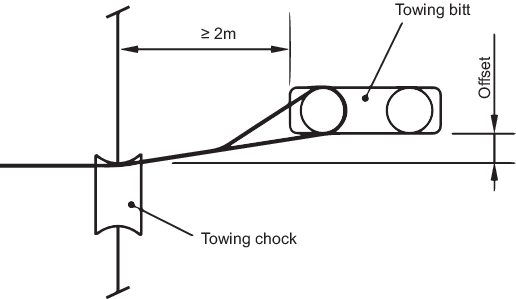
Figure 13.7.2 Typical towing arrangement
7.9 Mooring and towline construction
7.9.1 Towlines and mooring lines are to be of wire, natural fibre or synthetic fibre
construction or of a mixture of wire and fibre. For synthetic fibre ropes it is
recommended that lines with reduced risk of recoil (snap-back) be used to mitigate
the risk of injuries or fatalities in the case mooring line failure.
7.9.2 Notwithstanding the strength recommendations in Pt 3, Ch 13, 7.5 Mooring lines (Equipment Number ≤ 2000),
Pt 3, Ch 13, 7.6 Mooring lines (Equipment Number > 2000) and
Pt 3, Ch 13, 7.8 Towline and towing arrangement, no fibre
rope shall be less than 20 mm in diameter. For polyamide ropes the line design break
force is to be increased by 20 per cent and for other synthetic ropes by 10 per
cent to account for strength loss due to, among other causes, aging and wear. The
line design break force is defined in Pt 3, Ch 13, 9.1 General 9.1.9.
7.9.3 Wire ropes used for towlines and mooring lines are generally to be of a flexible
construction with not less than 144 wires in six strands with seven fibre cores for
strengths up to 490 kN, and 222 wires in six strands with one fibre core for
strengths exceeding 490 kN. The wires laid round the fibre centre of each strand are
to be made up in not less than two layers.
7.9.4 Wire ropes for towlines and mooring lines used in association with
mooring winches (on which the rope is stored on the winch drum) are to be of
suitable construction.
7.9.5 The towing and mooring lines are to be tested in accordance with Ch 10, 6 Steel wire ropes and Ch 10, 7 Fibre ropes of the Rules for the Manufacture, Testing and Certification of Materials, July 2022 for wire ropes and fibre ropes, respectively.
Table 13.7.4 Equipment – Stream anchors,
stream wires, towlines and mooring lines
| Equipment Number
|
Stockless stream anchor
|
Stream wire or chain (see Note
1)
|
Mooring lines (see Note
2)
|
Towline
|
|
Exceeding
|
Not exceeding
|
Mass per anchor
|
Length
|
Breaking strength
|
No. of mooring lines
|
Minimum length of each line
|
Ship design minimum breaking load
|
Minimum length
|
Ship design minimum breaking load
|
|
|
|
(kg)
|
(m)
|
(kN)
|
|
(m)
|
(kN)
|
(m)
|
(kN)
|
| 50
|
70
|
60
|
80
|
64,7
|
3
|
80
|
37
|
180
|
98
|
| 70
|
90
|
80
|
85
|
73,5
|
3
|
100
|
40
|
180
|
98
|
| 90
|
110
|
100
|
85
|
80
|
3
|
110
|
42
|
180
|
98
|
| 110
|
130
|
120
|
90
|
89,2
|
3
|
110
|
48
|
180
|
98
|
| 130
|
150
|
140
|
90
|
98,1
|
3
|
120
|
53
|
180
|
98
|
| 150
|
175
|
165
|
90
|
107,9
|
3
|
120
|
59
|
180
|
98
|
| 175
|
205
|
190
|
90
|
117,7
|
3
|
120
|
64
|
180
|
112
|
| 205
|
240
|
|
|
|
4
|
120
|
69
|
180
|
129
|
| 240
|
280
|
|
|
|
4
|
120
|
75
|
180
|
150
|
| 280
|
320
|
|
|
|
4
|
140
|
80
|
180
|
174
|
| 320
|
360
|
|
|
|
4
|
140
|
85
|
180
|
207
|
| 360
|
400
|
|
|
|
4
|
140
|
96
|
180
|
224
|
| 400
|
450
|
|
|
|
4
|
140
|
107
|
180
|
250
|
| 450
|
500
|
|
|
|
4
|
140
|
117
|
180
|
277
|
| 500
|
550
|
|
|
|
4
|
160
|
134
|
190
|
306
|
| 550
|
600
|
|
|
|
4
|
160
|
143
|
190
|
338
|
| 600
|
660
|
|
|
|
4
|
160
|
160
|
190
|
370
|
| 660
|
720
|
|
|
|
4
|
160
|
171
|
190
|
406
|
| 720
|
780
|
|
|
|
4
|
170
|
187
|
190
|
441
|
| 780
|
840
|
|
|
|
4
|
170
|
202
|
190
|
479
|
| 840
|
910
|
|
|
|
4
|
170
|
218
|
190
|
518
|
| 910
|
980
|
|
|
|
4
|
170
|
235
|
190
|
559
|
| 980
|
1060
|
|
|
|
4
|
180
|
250
|
200
|
603
|
| 1060
|
1140
|
|
|
|
4
|
180
|
272
|
200
|
647
|
| 1140
|
1220
|
|
|
|
4
|
180
|
293
|
200
|
691
|
| 1220
|
1300
|
|
|
|
4
|
180
|
309
|
200
|
738
|
| 1300
|
1390
|
|
|
|
4
|
180
|
336
|
200
|
786
|
| 1390
|
1480
|
|
|
|
4
|
180
|
352
|
200
|
836
|
| 1480
|
1570
|
|
|
|
5
|
190
|
352
|
220
|
888
|
| 1570
|
1670
|
|
|
|
5
|
190
|
362
|
220
|
941
|
| 1670
|
1790
|
|
|
|
5
|
190
|
384
|
220
|
1024
|
| 1790
|
1930
|
|
|
|
5
|
190
|
411
|
220
|
1109
|
| 1930
|
2080 (see Note 2)
|
|
|
|
5
|
190
|
437
|
220
|
1168
|
| 2080
|
2230
|
|
|
|
|
|
|
240
|
1259
|
| 2230
|
2380
|
|
|
|
|
|
|
240
|
1356
|
| 2380
|
2530
|
|
|
|
|
|
|
240
|
1453
|
| 2530
|
2700
|
|
|
|
|
|
|
260
|
1471
|
| 2700
|
2870
|
|
|
|
|
|
|
260
|
1471
|
| 2870
|
3040
|
|
|
|
|
|
|
260
|
1471
|
| 3040
|
3210
|
|
|
|
|
|
|
280
|
1471
|
| 3210
|
3400
|
|
|
|
|
|
|
280
|
1471
|
| 3400
|
3600
|
|
|
|
|
|
|
280
|
1471
|
| 3600
|
-
|
|
|
|
|
|
|
300
|
1471
|
|
Note 1. The rope
used for stream wire is to be constructed of not less than 72
wires, made up into six strands.
Note 2. The mooring
lines are to be selected only for ships with equipment number
less than or equal to 2000.
|
Table 13.7.5 Equipment for fishing
vessels
| Equipment Number
|
Stockless bower anchors
|
Stud link chain cables for bower
anchors
|
Mooring lines
|
| Exceeding
|
Not exceeding
|
Number
|
Mass per anchor
|
Total length
|
Minimum diameter (mm)
|
|
|
|
| Mild steel
|
Special quality steel
|
Number
|
Minimum length of each line
|
Ship design minimum breaking load
|
| (kg)
|
(m)
|
(Grade U1) See Note 1
|
(Grade U2)
|
|
(m)
|
(kN)
|
| 30
|
40
|
2
|
80
|
165
|
11
|
-
|
2
|
50
|
29
|
| 40
|
50
|
2
|
100
|
192,5
|
11
|
-
|
2
|
60
|
29
|
|
|
|
|
|
|
|
|
|
|
|
| 50
|
60
|
2
|
120
|
192,5
|
12,5
|
-
|
2
|
60
|
29
|
| 60
|
70
|
2
|
140
|
192,5
|
12,5
|
-
|
2
|
80
|
29
|
| 70
|
80
|
2
|
160
|
220
|
14
|
12.5
|
2
|
100
|
34
|
| 80
|
90
|
2
|
180
|
220
|
14
|
12.5
|
2
|
100
|
36,8
|
| 90
|
100
|
2
|
210
|
220
|
16
|
14
|
2
|
110
|
36,8
|
|
|
|
|
|
|
|
|
|
|
|
| 100
|
110
|
2
|
240
|
220
|
16
|
14
|
2
|
110
|
39
|
| 110
|
120
|
2
|
270
|
247.5
|
17,5
|
16
|
2
|
110
|
39
|
| 120
|
130
|
2
|
300
|
247.5
|
17,5
|
16
|
2
|
110
|
44
|
| 130
|
140
|
2
|
340
|
275
|
19
|
17.5
|
2
|
120
|
44
|
| 140
|
150
|
2
|
390
|
275
|
19
|
17.5
|
2
|
120
|
49
|
| 150
|
175
|
2
|
480
|
275
|
22
|
19
|
2
|
120
|
54
|
| 175
|
205
|
2
|
570
|
302,5
|
24
|
20.5
|
2
|
120
|
59
|
| 205
|
240
|
2
|
660
|
302,5
|
26
|
22
|
2
|
120
|
64
|
| 240
|
280
|
2
|
780
|
330
|
28
|
24
|
3
|
120
|
71
|
| 280
|
320
|
2
|
900
|
357,5
|
30
|
26
|
3
|
140
|
78
|
|
|
|
|
|
|
|
|
|
|
|
| 320
|
360
|
2
|
1020
|
357,5
|
32
|
28
|
3
|
140
|
85,8
|
| 360
|
400
|
2
|
1140
|
385
|
34
|
30
|
3
|
140
|
93
|
| 400
|
450
|
2
|
1290
|
385
|
36
|
32
|
3
|
140
|
101
|
| 450
|
500
|
2
|
1440
|
412,5
|
38
|
34
|
3
|
140
|
108
|
| 500
|
550
|
2
|
1590
|
412,5
|
40
|
34
|
4
|
160
|
113
|
|
|
|
|
|
|
|
|
|
|
|
| 550
|
600
|
2
|
1740
|
440
|
42
|
36
|
4
|
160
|
118
|
| 600
|
660
|
2
|
1920
|
440
|
44
|
38
|
4
|
160
|
123
|
| 660
|
720
|
2
|
2100
|
440
|
46
|
40
|
4
|
160
|
127
|
|
Note 1. For
equipment number ≤ 110, short link chain cables may be
considered as an alternative to stud link chain cables.
|
|