
Section
1 Anchors
1.1 Scope
1.1.1 This Section
makes provision for the manufacture and testing of anchors constructed
from cast, forged and fabricated components.
1.1.2 This Section
is applicable to the following types of anchor:
-
Ordinary.
-
High holding power
(HHP).
-
Super high holding
power (SHHP).
1.1.3 In the context of this Section, the reference to swivels and swivel
shackles refers to those directly attached to the anchor shank in lieu of the
conventional 'D' shackle. For other mooring equipment swivels, see
Ch 10, 2.13 Fittings for chain cables.
1.2 Design requirements
1.3 Anchor holding power tests for HHP and SHHP anchors
1.3.1 Anchor designs for which approval is sought as HHP anchors are to be tested at sea to
show that they have holding powers of at least twice those of approved standard
stockless anchors of the same mass. In the case of SHHP anchors, a holding power of
at least four times that of an ordinary stockless anchor of same mass is to be
demonstrated.
1.3.2 Full scale tests are to be carried out at sea on various types of bottom, normally,
soft mud or silt, sand or gravel and hard clay or similar compounded material. The
tests are to be applied to anchors of mass which are as far as possible
representative of the full range of sizes proposed.
1.3.3 HHP and SHHP anchors are to be tested along with an ordinary stockless anchor to
establish the holding power. They are to be of approximately the same mass and
tested in association with the size of chain required for that anchor mass.
1.3.4 Where an ordinary stockless anchor is not available for testing a HHP anchor, the use
of a previously approved HHP anchor may be considered. For testing SHHP anchors, a
previously approved HHP or SHHP anchor may be considered.
1.3.5 The length of the cable attached to each anchor is to be such that the pull on the
shank remains horizontal during the test. For this purpose a scope of 10 is
considered normal but a scope of not less than 6 may be accepted. Scope is defined
as the ratio of length of cable to depth of water.
1.3.6 Three tests are to be taken for each anchor and each type of bottom. The stability of
the anchor and ease of breaking out are to be noted where possible. Tests are to be
carried out from a tug but, alternatively, shore based tests will be specially
considered The pull is to be measured by dynamometer. Measurements of pull, based on
the RPM/bollard pull curve of the tug will be considered as an alternative to a
dynamometer.
1.3.7 For approval and/or acceptance for a range of HHP anchor sizes, tests are to be
carried out for at least two anchor sizes. The mass of the maximum size approved is
not to be more than 10 times the mass of the largest size tested.
1.3.8 For approval and/or acceptance for a range of SHHP anchor sizes, at least three
anchor sizes are to be tested, indicative of the bottom, middle and top of the mass
range.
1.3.9 The holding power test load is not to exceed the proof load of the anchor.
1.4 Cast steel anchors
1.4.2 Swivel and swivel shackles shall be manufactured to at least Grade U2.
Special consideration will be given to the use of other grades of steel.
1.4.3 To confirm
the quality of cast anchor components, the Surveyor is to witness
drop and hammering tests.
1.4.4 When drop
and hammering tests are required, they are to be carried out as follows:
-
Each anchor, or the
components of an anchor made from more than one piece, is to be dropped
from a clear height of 4 m onto a steel slab laid on a solid foundation.
-
Separately cast shanks and shackles are to be suspended horizontally
from a clear height of 4 m before being dropped. Cast anchor flukes are to be
suspended vertically, from a clear height of 4 m before being dropped.
Alternatively, a horizontal drop test for the anchor fluke can be carried out as
agreed by the manufacturer and Surveyor.
-
Anchors cast in one
piece are to be drop tested twice from a clear height of 4 m. For
the first test, the shank and flukes are to be horizontal. For the
second test, two steel blocks are to be placed on the slab, arranged
so that the middle of each fluke makes contact with the blocks without
the crown making contact with the slab, and the orientation of the
anchor is to be vertical with the crown nearest the slab.
-
If the slab is broken
by the impact, the test is to be repeated on a new slab.
1.4.5 When hammering
tests are required, they are to be carried out after the drop test
on each anchor head and shank, which is slung clear of the ground,
using a nonmetallic sling, and hammered to check the soundness of
the component. A hammer of at least 3 kg mass is to be used.
1.4.6 As part
of the manufacturer’s works approval, consideration may be given
to carrying out drop tests in alternative locations to the manufacturer’s
when the facilities and location are not suitable.
1.4.7 Repair of
fractures or unsoundness detected during the drop or hammering tests
are not permitted and the component is to be rejected.
1.5 Forged steel anchors
1.5.2 Swivel and swivel shackles shall be manufactured to at least Grade U2.
Special consideration will be given to other grades of steel.
1.6 Fabricated steel anchors
1.6.3 Stress relief
is to be carried out as required in the approved welding procedure.
1.7 Rectification
1.7.1 All rectification
is to be agreed with the Surveyor.
1.7.4 Rectification
of defective fabricated anchors is to be carried out by suitably qualified
welders within the parameters of the approved welding procedure used
in construction.
1.8 Super high holding power (SHHP) anchors
1.9 Assembly
1.9.1 Assembly and fitting, including any accessories, is to be carried out in
accordance with the approved design.
1.9.2 Securing of anchor pins, shackle pins, swivels or swivel shackles by
welding is to be carried out by suitably qualified welders in accordance with an
approved welding procedure.
1.10 Proof test of anchors
1.10.1 Anchors are to be tested in the presence of the Surveyor at a proving
establishment recognised by LR. A list of recognised proving establishments is published
separately by LR. In addition to the requirements stated in this Chapter, attention must
be given to any relevant statutory requirements of the National Authority of the country
in which the ship or mobile offshore unit is to be registered.
1.10.2 The anchor
is to be visually examined before application of the proof test load
to ensure that it is free from cracks, notches, inclusions and other
surface defects that would impair the performance of the product.
1.10.3 As required by Ch 10, 1.10 Proof test of anchors, each anchor is to be subjected
to a proof loading test in an approved testing machine and is to withstand the load
given in Table 10.1.1 Proof load tests for anchors
(see Notes 1 and 2) for the appropriate mass of the
anchor. The proof load is to be applied on the arm or on the palm at a spot which,
measured from the extremity of the bill, is one-third of the distance between it and the
centre of the crown. For stocked anchors, each arm is to be tested individually. For
stockless anchors, both arms are to be tested at the same time, first on one side of the
shank, then reversed and tested on the other.
Table 10.1.1 Proof load tests for anchors
(see Notes 1 and 2)
| Mass
of anchor (Ch 10, 1.10 Proof test of anchors 1.10.5)
|
Proof
test load
|
Mass
of anchor (Ch 10, 1.10 Proof test of anchors 1.10.5)
|
Proof
test load
|
Mass
of anchor (Ch 10, 1.10 Proof test of anchors 1.10.5)
|
Proof
test load
|
| kg
|
kN
|
kg
|
kN
|
kg
|
kN
|
| 50
|
23,2
|
2200
|
376,0
|
7800
|
861,0
|
| 55
|
25,2
|
2300
|
388,0
|
8000
|
877,0
|
| 60
|
27,1
|
2400
|
401,0
|
8200
|
892,0
|
| 65
|
28,9
|
2500
|
414,0
|
8400
|
908,0
|
|
|
|
|
|
|
|
| 70
|
30,7
|
2600
|
427,0
|
8600
|
922,0
|
| 75
|
32,4
|
2700
|
438,0
|
8800
|
936,0
|
| 80
|
33,9
|
2800
|
450,0
|
9000
|
949,0
|
| 90
|
36,3
|
2900
|
462,0
|
9200
|
961,0
|
|
|
|
|
|
|
|
| 100
|
39,1
|
3000
|
474,0
|
9400
|
975,0
|
| 120
|
44,3
|
3100
|
484,0
|
9600
|
987,0
|
| 140
|
49,0
|
3200
|
495,0
|
9800
|
998,0
|
| 160
|
53,3
|
3300
|
506,0
|
10 000
|
1010,0
|
|
|
|
|
|
|
|
| 180
|
57,4
|
3400
|
517,0
|
10
500
|
1040,0
|
| 200
|
61,3
|
3500
|
528,0
|
11
000
|
1070,0
|
| 225
|
65,8
|
3600
|
537,0
|
11
500
|
1090,0
|
| 250
|
70,4
|
3700
|
547,0
|
12 000
|
1110,0
|
|
|
|
|
|
|
|
| 275
|
74,9
|
3800
|
557,0
|
12
500
|
1130,0
|
| 300
|
79,5
|
3900
|
567,0
|
13
000
|
1160,0
|
| 325
|
84,1
|
4000
|
577,0
|
13
500
|
1180,0
|
| 350
|
88,8
|
4100
|
586,0
|
14 000
|
1210,0
|
|
|
|
|
|
|
|
| 375
|
93,4
|
4200
|
595,0
|
14
500
|
1230,0
|
| 400
|
97,9
|
4300
|
604,0
|
15
000
|
1260,0
|
| 425
|
103,0
|
4400
|
613,0
|
15
500
|
1280,0
|
| 450
|
107,0
|
4500
|
622,0
|
16 000
|
1300,0
|
|
|
|
|
|
|
|
| 475
|
112,0
|
4600
|
631,0
|
16
500
|
1330,0
|
| 500
|
116,0
|
4700
|
638,0
|
17
000
|
1360,0
|
| 550
|
125,0
|
4800
|
645,0
|
17
500
|
1390,0
|
| 600
|
132,0
|
4900
|
653,0
|
18 000
|
1410,0
|
|
|
|
|
|
|
|
| 650
|
140,0
|
5000
|
661,0
|
18
500
|
1440,0
|
| 700
|
149,0
|
5100
|
669,0
|
19
000
|
1470,0
|
| 750
|
158,0
|
5200
|
677,0
|
19
500
|
1490,0
|
| 800
|
166,0
|
5300
|
685,0
|
20 000
|
1520,0
|
|
|
|
|
|
|
|
| 850
|
175,0
|
5400
|
691,0
|
21
000
|
1570,0
|
| 900
|
182,0
|
5500
|
699,0
|
22
000
|
1620,0
|
| 950
|
191,0
|
5600
|
706,0
|
23
000
|
1670,0
|
| 1000
|
199,0
|
5700
|
713,0
|
24 000
|
1720,0
|
|
|
|
|
|
|
|
| 1050
|
208,0
|
5800
|
721,0
|
25
000
|
1770,0
|
| 1100
|
216,0
|
5900
|
728,0
|
26
000
|
1800,0
|
| 1150
|
224,0
|
6000
|
735,0
|
27
000
|
1850,0
|
| 1200
|
231,0
|
6100
|
740,0
|
28 000
|
1900,0
|
|
|
|
|
|
|
|
| 1250
|
239,0
|
6200
|
747,0
|
29
000
|
1940,0
|
| 1300
|
247,0
|
6300
|
754,0
|
30
000
|
1990,0
|
| 1350
|
255,0
|
6400
|
760,0
|
31
000
|
2030,0
|
| 1400
|
262,0
|
6500
|
767,0
|
32 000
|
2070,0
|
|
|
|
|
|
|
|
| 1450
|
270,0
|
6600
|
773,0
|
34
000
|
2160,0
|
| 1500
|
278,0
|
6700
|
779,0
|
36
000
|
2250,0
|
| 1600
|
292,0
|
6800
|
786,0
|
38
000
|
2330,0
|
| 1700
|
307,0
|
6900
|
794,0
|
40 000
|
2410,0
|
|
|
|
|
|
|
|
| 1800
|
321,0
|
7000
|
804,0
|
42
000
|
2490,0
|
| 1900
|
335,0
|
7200
|
818,0
|
44
000
|
2570,0
|
| 2000
|
349,0
|
7400
|
832,0
|
46
000
|
2650,0
|
| 2100
|
362,0
|
7600
|
845,0
|
48 000
|
2730,0
|
| Proof loads for intermediate mass are to be determined by linear
interpolation
|
Note
1. Where ordinary anchors have a mass
exceeding 48 000 kg, the proof loads are to be taken as 2,059 (mass of
anchor in kg)2 / 3 kN.
Note
2. Where high holding power anchors have
a mass exceeding 36 000 kg, the proof loads are to be taken as 2,452
(actual mass of anchor in kg)2 / 3 kN.
|
1.10.4 The general arrangements for the test are to be such that the complete
anchor, including the shackle, shackle pins, swivel or swivel shackle and any welded or
bolted connections are included in the test. If a replacement shackle, swivel or swivel
shackle is needed which requires welding or heating for fitting, the combined anchor and
accessories are to be proof load tested. If welding or heating is not involved in
fitting, the accessories may be proof load tested separately from the anchor.
1.10.5 The mass
to be used in Table 10.1.1 Proof load tests for anchors
(see Notes 1 and 2) is:
-
For stockless anchors,
the total mass of the anchor.
-
For stocked anchors,
the mass of the anchor excluding the stock.
-
For high holding power
anchors, a nominal mass equal to 1,33 times the actual total mass
of the anchor.
-
For mooring anchors,
including positional mooring anchors, a nominal mass equal to 1,33
times the actual total mass of the anchor, unless specifically agreed
otherwise.
-
For super high holding
power anchors, a nominal mass equal to twice the actual total mass
of the anchor.
1.10.6 For positional
mooring anchors, the proof test loading is to be that required by Ch 10, 1.10 Proof test of anchors 1.10.3 or 50 per cent of the minimum
break strength of the intended anchor line, whichever is the greater.
1.10.7 The gauge
length is to be measured with 10 per cent of the required load applied,
before and after proof test. The two measurements shall differ by
no more than 1 per cent. The gauge length is the distance between
the tip of each fluke and a point on the shank adjacent to the shackle
pin, see
Figure 10.1.1 Location of gauge length measurement during proof load.
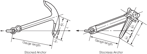
Figure 10.1.1 Location of gauge length measurement during proof load
1.10.8 After proof
testing, all accessible surfaces are to be visually inspected by the
Surveyor.
1.10.9 Following
proof testing, NDE is to be conducted as described in Table 10.1.2 NDE requirements following proof
testing for Ordinary and HHP anchors for ordinary and HHP anchors
and Table 10.1.3 NDE requirements following proof
testing for SHHP anchors for SHHP anchors.
Table 10.1.2 NDE requirements following proof
testing for Ordinary and HHP anchors
| Location
|
Method of NDE
|
| Feeder heads, runners and risers of
castings
|
Magnetic particle inspection and ultrasonic
test, see Note 1
|
| All welds
|
Magnetic particle inspection
|
| Forged components
|
Not required
|
| Fabrication welds
|
Magnetic particle inspection
|
Note
2. Penetrant testing is to be used in
lieu of magnetic particle testing for stainless steel, aluminium and
copper alloy anchors.
|
Table 10.1.3 NDE requirements following proof
testing for SHHP anchors
| Location
|
Method of NDE
|
| Feeder heads, runners and risers of
castings
|
Magnetic particle inspection and ultrasonic
test, see Note 1
|
| All surfaces of castings
|
Magnetic particle inspection
|
| All welds
|
Magnetic particle inspection
|
| Forged components
|
Not required
|
| Fabrication welds
|
Magnetic particle
inspection
|
Note
2. Additionally, all surfaces of all SHHP
anchors are to be surface inspected by the magnetic particle or
penetrant method as appropriate.
Note
3. Penetrant is to be used in lieu of
magnetic particle testing for stainless steel, aluminium and copper
alloy anchors.
|
1.10.10 Each casting
is to be subjected to ultrasonic inspection in the region of runners
and risers, or where excess material has been removed by thermal methods.
This examination is to extend around the whole periphery of the casting
and for a distance of t/3 beyond the area affected, where
t is the maximum thickness. In addition, random areas are to be selected
by the Surveyor and examined.
1.10.13 Paint
or anti-corrosive coatings are not to be applied until these inspections
are completed to the satisfaction of the Surveyor.
1.10.14 On completion
of the proof testing, anchors made in more than one piece are to be
examined for free movement of their heads over the complete range
of rotation.
1.11 Clearances and tolerances
1.11.1 Where
no fitting tolerances are specified on the approved plans the following
assembly and fitting tolerance are to be applied.
1.11.2 The clearance
either side of the shank within the shackle jaws and the shackle pin
in the shank end hole is to be no more than 3 mm for small anchors
up to 3 tonnes, 4 mm for anchors up to 5 tonnes, 6 mm for anchors
up to 7 tonnes and is not to exceed 12 mm for larger anchors.
1.11.3 The shackle
pin to hole tolerance is to be no more than 0,5 mm for pins up to
57 mm and 1,0 mm for pins of larger diameter and the eyes of the shackle
are to be chamfered on the outside to ensure a good tightness when
the pin is fitted. The shackle pin is to mate with the shackle such
that it can be inserted with moderate hand pressure, allowing disassembly
if required.
1.11.4 The trunnion
pin is to fit within the chamber such that it will achieve the closest
fit which can be carried out by hand. The pin is to be long enough
to prevent horizontal movement. The gap is to be no more than 1 per
cent of the chamber length.
1.11.6 Unless otherwise agreed, the verification of mass and dimensions is the
responsibility of the manufacturer. The Surveyor is only required to monitor this
inspection. The mass of the anchor is to exclude the mass of the swivel or swivel
shackle, unless the swivel or swivel shackle is in lieu of the conventional ‘D’
shackle.
1.12 Identification
1.12.1 The manufacturer is to adopt a system of identification, as per the
requirements of Ch 1, 4.8 Identification of materials,
which will enable all anchor components to be traced to the original cast and the
Surveyor is to be given full facilities for tracing the castings when required.
1.12.2 Identification
marks on the shank are to be approximately level with the fluke tips.
On the fluke, these markings are to be approximately at a distance
of two thirds from the tip of the bill to the centre line of the crown
on the right hand fluke, looking from the crown towards the shank.
1.12.3 The following
details are to be shown on all anchors:
-
LR or Clasifications Register
and abbreviated name of LR's local office issuing the certificate.
-
Number of the certificate.
-
Month and year of
test.
-
Mass (also the letters
`HHP' when approved as high holding power anchors or ‘SHHP’
when approved as super high holding power anchors).
-
Mass of stock (in
the case of stocked anchors).
-
National Authority
requirements, as applicable.
-
Manufacturer's mark.
1.12.4 In addition
to Ch 10, 1.12 Identification 1.12.3, each important part
of an anchor is to be plainly marked by the maker with the words `forged
steel' or `cast steel' as appropriate. Fabricated steel anchor heads
do not require special marking.
1.13 Certification
1.13.1 The manufacturer
is to provide the Surveyor with a written statement that the anchor
has been manufactured and tested in accordance with LR Rules together
with the following particulars:
-
Purchaser`s name
and order number.
-
Type of anchor and
principal dimensions.
-
Mass of anchor.
-
Identification mark
which will enable the full history of manufacture to be traced.
-
Chemical composition.
-
Details of heat treatment.
-
Mechanical test results.
-
Proof load.
-
Results of the non-destrucive
examination.
-
Weld location maps
(cast steel anchors only).
1.13.3 An LR
Anchor Certificate is to be issued for the completed anchor which
will include the following particulars:
-
Manufacturer's name.
-
Type of anchor.
-
Mass of anchor.
-
Grade of materials.
-
Proof test load.
-
Heat treatment.
-
Marking applied to
anchor.
-
Dimensions.
-
General Approval
of an Anchor Design Certificate Number.
-
Fluke and shank identification
numbers.
|