
Section
2 Stud link chain cables for ships
2.1 Scope
2.1.1 Provision
is made in this Section for a range of grades, U1, U2 and U3, of stud
link chain and fittings intended for anchor cables for ships.
2.1.3 The design of chain cables and fittings is to be to a Standard recognised
by LR, such as ISO 1704.
2.2 Manufacture
2.2.1 All grades
of chain cable and accessories are to be manufactured by approved
procedures at works approved by LR. A list of approved manufacturers
of stud link chain cables and fittings is published separately by
LR.
2.2.3 As far as
practicable, consecutive links in all chain cable should originate
from a single cast or batch of bar stock (see
Ch 3, 9.6 Mechanical tests 9.6.1), and indicating marks should
be stamped on the final link formed from one cast or batch and the
first link formed from a separate cast or batch.
2.2.4 A length
of chain cable is to measure not more than 27,5m and is to comprise
an odd number of links. In this context, a length is a statutory term
and is the basis for the number of test samples.
2.2.5 Where end
links or enlarged links are manufactured and heat treated as part
of and at the same time as the chain cable and are of the same cast
heat of steel, they may be excluded from separate mechanical tests
and break load tests.
2.3 Flash butt welded chain cable
2.3.1 Bar material
is to comply with the requirements of Ch 3, 9 Bars for welded chain cables and
may be heated either by electrical resistance or in a furnace. For
electrical resistance heating, the process is to be controlled by
an optical heat sensor. For furnace heating, thermocouples in close
proximity to the bars are to be used for control. The temperature
is to be continuously recorded. In both cases, the controls are to
be checked at least once every eight hours and checks are to be recorded.
2.3.2 Mechanical
properties testing of U1 cable is not required. For Grade U2 cable
supplied in the as-welded condition, and Grade U3 in all conditions,
one tensile and one set of three Charpy V-notch impact test specimens
are to be taken at the side of a link opposite the weld from at least
every fourth 27,5m length of cable. A further set of three impact
test specimens is to be taken with the notch positioned at the centre
of the weld, see
Table 10.2.3 Condition of supply and scope of
mechanical tests for finished chain cables and fittings.
The test specimens are not to be selected from the same length as
that from which the breaking test sample is taken, unless breaking
test samples are to be taken from every length of the batch. All test
samples are to be correctly identified with the lengths of cable represented.
2.3.3 The test
links from which the mechanical test specimens are prepared are to
be made as part of the chain cable and are to be heat treated with
it. They may be removed from the cable prior to heat treatment provided
that each sample is heat treated with, and in the same manner as,
the chain it represents prior to preparation of the mechanical test
specimens.
2.4 Cast chain cables
2.4.1 The manufacture
of cast steel chain cable is generally to be in accordance with the
requirements of Ch 4, 1 General requirements, as appropriate.
2.4.2 The chemical
composition of ladle samples is to comply with the specification approved
by LR.
2.4.4 Tensile
and Charpy V-notch impact test specimens are to be taken from each
test sample and machined to the dimensions given in Ch 2, 3 Impact tests.
2.5 Forged chain cables
2.5.1 The procedure
for the manufacture and testing of drop forgings for chain cable will
be specially considered, but is generally to be in accordance with
the appropriate requirements of Ch 5, 1 General requirements.
2.5.4 Test samples
are to be provided in the form of forgings of similar dimensions to
the links they represent. These test samples are to be from the same
steel-making heat and heat treated together with the links they represent.
2.5.5 One tensile
and three Charpy V-notch specimens are to be taken from each test
sample.
2.5.6 The results
of mechanical tests are to comply with the requirements of Table 10.2.1 Mechanical properties of finished
chain cable and fittings for the relevant grade.
Table 10.2.1 Mechanical properties of finished
chain cable and fittings
| Grade
|
Yield stress N/mm2
minimum
|
Tensile strength N/mm2
|
Elongation on 5,65 % minimum % minimum
|
Reduction of area % minimum
|
Charpy V-notch
impact tests
|
Test
temperature
°C
|
Average energy
J
minimum
|
| U2
|
295
|
490 –
690
|
22
|
—
|
0
|
27
|
|
|
|
|
|
|
(see Note 1)
|
|
| U3
|
410
|
690
minimum
|
17
|
40
|
0
|
60
|
|
|
|
|
|
|
–20
(see Note 2)
|
35
|
Note
2. Testing may be carried out at either
0°C or –20°C.
Note
3. Mechanical testing is not required for
finished chain cables and fittings in Grade U1.
|
Table 10.2.2 Chemical composition of butt
welded and forged chain cable
| Grade
|
Chemical composition %
|
| C
|
Si
|
Mn
|
P
|
S
|
Al
|
N
|
Cr
|
Cu
|
Nb
|
Ni
|
V
|
Mo
|
| max.
|
|
|
max.
|
max.
|
|
max.
|
max.
|
max.
|
max.
|
max.
|
max.
|
max.
|
| U1
|
0,20
|
0,15 –
0,35
|
0,40
min.
|
0,04
|
0,04
|
—
|
—
|
—
|
—
|
—
|
—
|
—
|
—
|
| U2
|
0,24
|
0,15 –
0,55
|
1,60
max.
|
0,035
|
0,035
|
0,02
min. see Note 1
|
—
|
—
|
—
|
—
|
—
|
—
|
—
|
| U3
|
0,33
|
0,15 –
0,55
|
1,90
max.
|
0,035
|
0,035
|
0,065
max. see Note 2
|
0,015
|
0,25
|
0,35
|
0,05
see Note 2
|
0,40
|
0,10
see Note 2
|
0,08
|
Note
1. Aluminium may be partly replaced by
other grain refining elements.
Note
2. To obtain fine grain steel, at least
one of these grain refining elements must be present in sufficient
amount.
|
Table 10.2.3 Condition of supply and scope of
mechanical tests for finished chain cables and fittings
| Grade
|
Manufacturing method
|
Condition of supply
|
Number of test specimens on every four lengths of chain
cable of 27,5 m or less, or on each batch of fittings
|
| Tensile test on base materials
|
Charpy V-notch impact test
|
| Base
material
|
Weldment
|
| U1
cable
|
Flash
butt welded
|
As welded
|
—
|
—
|
—
|
| Normalised
|
—
|
—
|
—
|
| U2
cable
|
Flash
butt welded
|
As welded
|
1
|
3
|
3
|
| Normalised
|
—
|
—
|
—
|
| U3
cable
|
Flash
butt welded
|
Normalised
|
|
|
|
| Normalised and
Tempered
|
1
|
3
|
3
|
| Quenched and
Tempered
|
|
|
|
| U2 cable
|
Cast or drop
forged
|
Normalised
|
1
|
3
|
—
|
| U3
cable
|
Cast
or drop forged
|
Normalised
|
1
|
3
|
—
|
| Normalised and
Tempered
|
| Quenched and
Tempered
|
| U2 fittings
|
Cast or drop
forged
|
Normalised
|
1
|
3
|
—
|
| U3
fittings
|
Cast
or drop forged
|
Normalised
|
1
|
3
|
—
|
| Normalised and
Tempered
|
| Quenched and
Tempered
|
2.6 Stud material
2.6.1 Steel studs
are to be used for all grades of welded chain cable. In general, the
carbon content should not exceed 0,23 per cent but mechanical tests
for acceptance purposes are not required.
2.7 Welding of studs
2.7.1 Where studs
are welded into the links this is to be completed before the chain
cable is heat treated.
2.7.2 The stud ends must be a good fit inside the link, and the weld is to be
confined to the stud end opposite the flash-butt weld. Welding of studs both ends is not
permitted unless specially approved. The full periphery of the stud end is to be welded.
If, however, it can be demonstrated to the Surveyor that the quality of welding is of a
high standard then partial peripheral welding may be accepted provided that welds are
made only at the sides of the stud and that each run extends continuously for at least
25 per cent of the stud periphery. Weld start/stop positions are not to be located in
the plane of the chain cable.
2.7.3 The welds
are to be made by qualified welders using an approved procedure and
consumables approved to Grade 3 and low hydrogen, in accordance with Ch 11 Approval of Welding Consumables.
2.7.4 The welds
are to be of good quality and free from defects liable to impair the
proper use of the chain. Undercuts, end craters and similar stress
raising defects shall, where necessary, be ground off.
2.7.5 All stud welds are to be visually inspected. At least one stud weld within
each length of cable is to be inspected using magnetic particle inspection or dye
penetrant testing in accordance with Ch 1, 5 Non-destructive examination after the chain has been proof loaded. If a crack is found, the
stud welds in the adjoining links are to be inspected; if a crack is found in either
link, all the stud welds in that length are to be inspected using magnetic particle
inspection or dye penetrant testing.
2.8 Heat treatment of completed chain cables
2.8.2 Special
consideration will be given to the heat treatment of certain types
of drop forged chain cable.
2.8.3 In all cases,
heat treatment is to be carried out prior to the proof loading and
breaking tests.
2.8.4 All test
samples are to be heat treated with, and in the same way as, the chain
cables they represent.
2.9 Testing of completed chain cables
2.9.2 All chain
cables are to be tested in the presence of a Surveyor, at a proving
establishment recognised by LR. A list of recognised proving establishments
is published separately by LR. In addition to the requirements stated
in this Chapter, attention must be given to any relevant statutory
requirements of the National Authority of the country in which the
ship is to be registered.
2.10 Proof load tests
2.10.1 Each length
of chain cable is to be subjected to a proof loading test in an approved
testing machine and is to withstand the load given in Table 10.2.4 Test loads for stud link anchor
chain cables for the appropriate grade
and size of cable.
Table 10.2.4 Test loads for stud link anchor
chain cables
Chain diameter
d mm
|
Grade U1
|
Grade U2
|
Grade U3
|
Proof
load kN
0,00686d
2
(44– 0,08d)
|
Breaking load kN
0,00981d
2
(44– 0,08d)
|
Proof
load kN
0,00981d
2
(44– 0,08d)
|
Breaking load kN
0,01373d
2
(44– 0,08d)
|
Proof
load kN
0,01373d
2
(44– 0,08d)
|
Breaking load kN
0,01961d
2
(44– 0,08d)
|
| 12,5
|
46
|
66
|
66
|
92
|
92
|
132
|
| 14
|
58
|
82
|
82
|
115
|
115
|
165
|
| 16
|
75
|
107
|
107
|
150
|
150
|
214
|
| 17,5
|
89
|
128
|
128
|
179
|
179
|
256
|
| 19
|
105
|
150
|
150
|
211
|
211
|
301
|
|
|
|
|
|
|
|
|
| 20,5
|
122
|
175
|
175
|
244
|
244
|
349
|
| 22
|
140
|
201
|
201
|
281
|
281
|
401
|
| 24
|
166
|
238
|
238
|
333
|
333
|
475
|
| 26
|
194
|
278
|
278
|
389
|
389
|
556
|
| 28
|
225
|
321
|
321
|
450
|
450
|
642
|
|
|
|
|
|
|
|
|
| 30
|
257
|
367
|
367
|
514
|
514
|
734
|
| 32
|
291
|
416
|
416
|
583
|
583
|
832
|
| 34
|
327
|
468
|
468
|
655
|
655
|
936
|
| 36
|
366
|
523
|
523
|
732
|
732
|
1045
|
| 38
|
406
|
580
|
580
|
812
|
812
|
1160
|
|
|
|
|
|
|
|
|
| 40
|
448
|
640
|
640
|
896
|
896
|
1280
|
| 42
|
492
|
703
|
703
|
984
|
984
|
1406
|
| 44
|
538
|
769
|
769
|
1076
|
1076
|
1537
|
| 46
|
585
|
837
|
837
|
1171
|
1171
|
1673
|
| 48
|
635
|
908
|
908
|
1270
|
1270
|
1814
|
|
|
|
|
|
|
|
|
| 50
|
686
|
981
|
981
|
1373
|
1373
|
1961
|
| 52
|
739
|
1057
|
1057
|
1479
|
1479
|
2113
|
| 54
|
794
|
1135
|
1135
|
1589
|
1589
|
2269
|
| 56
|
850
|
1216
|
1216
|
1702
|
1702
|
2430
|
| 58
|
908
|
1299
|
1299
|
1818
|
1818
|
2597
|
|
|
|
|
|
|
|
|
| 60
|
968
|
1384
|
1384
|
1938
|
1938
|
2767
|
| 62
|
1029
|
1472
|
1472
|
2060
|
2060
|
2943
|
| 64
|
1092
|
1562
|
1562
|
2187
|
2187
|
3123
|
| 66
|
1157
|
1655
|
1655
|
2316
|
2316
|
3308
|
| 68
|
1223
|
1749
|
1749
|
2448
|
2448
|
3496
|
|
|
|
|
|
|
|
|
| 70
|
1291
|
1846
|
1846
|
2583
|
2583
|
3690
|
| 73
|
1395
|
1995
|
1995
|
2792
|
2792
|
3988
|
| 76
|
1503
|
2149
|
2149
|
3007
|
3007
|
4295
|
| 78
|
1576
|
2254
|
2254
|
3154
|
3154
|
4505
|
| 81
|
1689
|
2415
|
2415
|
3380
|
3380
|
4827
|
|
|
|
|
|
|
|
|
| 84
|
1805
|
2580
|
2580
|
3612
|
3612
|
5158
|
| 87
|
1923
|
2750
|
2750
|
3849
|
3849
|
5498
|
| 90
|
2045
|
2924
|
2924
|
4093
|
4093
|
5845
|
| 92
|
2127
|
3042
|
3042
|
4258
|
4258
|
6081
|
| 95
|
2254
|
3223
|
3223
|
4510
|
4510
|
6442
|
|
|
|
|
|
|
|
|
| 97
|
2339
|
3345
|
3345
|
4682
|
4682
|
6687
|
| 100
|
2470
|
3532
|
3532
|
4943
|
4943
|
7060
|
| 102
|
2558
|
3658
|
3658
|
5120
|
5120
|
7312
|
| 105
|
2692
|
3850
|
3850
|
5389
|
5389
|
7697
|
| 107
|
2783
|
3980
|
3980
|
5571
|
5571
|
7957
|
|
|
|
|
|
|
|
|
| 111
|
2968
|
4245
|
4245
|
5941
|
5941
|
8486
|
| 114
|
3110
|
4447
|
4447
|
6224
|
6224
|
8889
|
| 117
|
3253
|
4652
|
4652
|
6511
|
6511
|
9299
|
| 120
|
3398
|
4859
|
4859
|
6801
|
6801
|
9714
|
| 122
|
3496
|
4999
|
4999
|
6997
|
6997
|
9994
|
|
|
|
|
|
|
|
|
| 124
|
3595
|
5141
|
5141
|
7195
|
7195
|
10276
|
| 127
|
3744
|
5354
|
5354
|
7494
|
7494
|
10703
|
| 130
|
3895
|
5571
|
5571
|
7796
|
7796
|
11135
|
| 132
|
3997
|
5716
|
5716
|
8000
|
8000
|
11426
|
| 137
|
4254
|
6083
|
6083
|
8514
|
8514
|
12161
|
|
|
|
|
|
|
|
|
| 142
|
4515
|
6456
|
6456
|
9036
|
9036
|
12906
|
| 147
|
4779
|
6834
|
6834
|
9565
|
9565
|
13662
|
| 152
|
5046
|
7217
|
7217
|
10100
|
10100
|
14426
|
| 157
|
5316
|
7602
|
7602
|
10640
|
10640
|
15197
|
| 162
|
5588
|
7991
|
7991
|
11185
|
11185
|
15975
|
2.10.2 On completion
of the test, each link is to be visually examined and is to be free
from significant defects. Special attention is to be given to welds.
2.10.3 Should
any link be found to be defective it is to be replaced by an approved
connecting link (joining shackle or substitute link as detailed in Ch 10, 2.14 Substitute single links). The chain is then to be subjected
to a repeat of the proof load test followed by re-examination.
2.10.4 If a link
breaks during proof load testing, a sample consisting of three common
links is to be taken from each side of the broken link and subjected
to a breaking test as detailed in Ch 10, 2.12 Breaking load tests.
If either of these samples fails, the length of cable is not to be
accepted. A thorough examination of all broken links is to be made
to determine the cause of failure and, after evaluation, LR will consider
the extent of cable which is to be rejected.
2.11 Dimensional inspection
2.11.2 On every
27,5 m length of chain, five links are to be selected for measurement
of length to ensure that the maximum allowable tolerance on a length
of five links is plus 2,5 per cent. No under-tolerance is permitted.
2.11.3 If a five-link
length of chain exceeds the tolerance given in Ch 10, 2.11 Dimensional inspection 2.11.2, then the entire chain is to
be checked for length, five links at a time with an overlap of two
links, which is to include the first five links. Oversize links are
to be removed and an approved connecting link inserted.
2.11.4 Checks
of all other dimensions are to be made on three links from every four
27,5 m lengths. All measurements are to be made on links selected
by the Surveyor and are to be carried out to the Surveyor’s
satisfaction.
2.11.6 If more
than one link in a 27,5 m length of chain cable fails to meet the
tolerance requirements, all the links in that length are to be measured.
2.11.7 Links
that fail to comply with tolerance requirements are to be removed
and approved connecting links inserted. Where a significant number
of links fail to comply with the tolerance requirements the chain
is to be rejected.
2.11.9 Manufacturing
tolerances on stud link chain are to be within ±2,5 per cent
(taking into account that all components of the chain are to be a
good fit with one another), except for those detailed in Ch 10, 2.11 Dimensional inspection 2.11.10.
2.11.10 The nominal diameter, d, is to be the average of the diameters,
measured in the plane of the link, d
c, and perpendicular to the plane of the link, d
p, see
Figure 10.2.2 Common link. The negative tolerance on the
nominal diameter is not to exceed the following:
-
Minus 1 mm when d ≤ 40 mm
-
Minus 2 mm when 40 mm < d ≤ 84 mm
-
Minus 3 mm when 84 mm < d ≤ 122 mm
-
Minus 4 mm when d > 122 mm
For diameters of 20mm or greater, the plus tolerance on the diameter at the
crown measured perpendicular to the plane of the link, d
p, is not to exceed 5 per cent. For diameters less than 20mm, the plus
tolerance is to be agreed between the chain manufacturer and bar material supplier.
2.11.11 The
cross-sectional area is to be calculated using the nominal diameter, d. The cross-sectional area at the crown of the link is to
have no negative tolerance.
2.11.12 The diameter measured at locations other than the crown is to have no
negative tolerance. For diameters of 20mm or greater, the plus tolerance may be up to 5
percent of the nominal diameter except at the butt weld where it is to be in accordance
with the manufacturer’s specification, which is to be agreed by LR. For diameters less
than 20mm, the plus tolerance is to be agreed between the chain manufacturer and bar
material supplier.
2.11.13 Studs must be located in the links centrally and at right angles to the
sides of the link, although the studs at each end of any length may also be located
off-centre to facilitate the insertion of the joining shackle. The following tolerances
in Figure 10.2.1 Manufacturing tolerances will be accepted provided that the stud fits
snugly and its ends lie practically flush against the inside of the link:
-
Maximum off-centre distance ‘X’: 10 per cent
of the nominal diameter d
-
Maximum deviation ‘α’ from the 90° –
position: 4°.
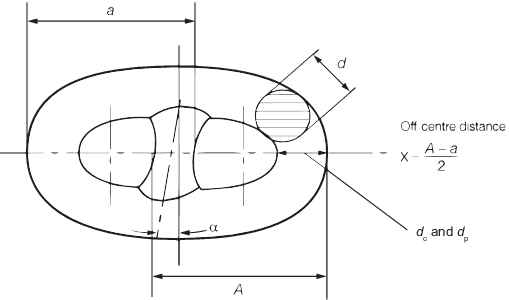
Figure 10.2.1 Manufacturing tolerances
2.11.14 All
individual parts must have a clean surface consistent with the method
of manufacture and the surface is to be free from cracks, notches,
inclusions and other defects which could impair the performance of
the product. Crack-like imperfections less than 3 mm in length can
be ignored. The flash produced by upsetting or drop forging must be
properly removed.
2.11.15 Minor
surface imperfections may be ground off so as to leave a gentle transition
to the surrounding surface provided that the cross-sectional area
remains equal to or greater than the nominal cross-sectional area.
Remote from the crown, local grinding up to 5 per cent of the nominal
diameter may be permitted.
2.11.16 Paint
or anti-corrosive coatings are not to be applied until these inspections
are completed to the satisfaction of the Surveyor.
2.12 Breaking load tests
2.12.1 Breaking
load tests are to be carried out on three-link samples selected by
the Surveyor from the completed (including heat treatment) chain.
The test links may be removed from the chain prior to heat treatment
provided that each sample is heat treated with, and in the same manner
as the chain it represents. They are to be properly identified with
the lengths of chain they represent.
2.12.3 Breaking
test specimens are to withstand the load given in Table 10.2.4 Test loads for stud link anchor
chain cables for the appropriate grade
and size of cable. The specimen is considered to have passed this
test if it has shown no sign of fracture after application of the
required load for a minimum of 30 seconds.
Table 10.2.5 Number of breaking tests from
completed cables
| Designation
|
Method of manufacture
|
Number of breaking test
specimens
|
| Grade
|
U1
|
Flash-butt welded and heat
treated
|
One from every four lengths of 27,5 m
or less
|
| Grade
|
U2(a)
|
Flash-butt welded, or
drop forged and heat treated
|
One from every four
lengths of 27,5 m or less
|
|
|
U3(a)
|
| Grade
|
U1
|
Flash-butt welded but not
heat treated
|
One from each length of
27,5 m or less
|
|
|
U2(a)
|
| Grade
|
U2(b)
|
Cast and heat treated
|
One per heat treatment
batch with a minimum of one from every four lengths of 27,5 m or
less
|
|
|
U3(b)
|
|
Table 10.2.6 Mechanical properties of welds in
chain cables
| Grade
|
Charpy V-notch impact test
|
Test
temperature
°C
|
Average energy J
min
|
| U1
|
—
|
—
|
| U2
|
0
(see Note 1)
|
27
|
| U3
|
0
|
50
|
|
|
–20
(see Note 2)
|
27
|
Note
1. Impact tests are only required if the
chain cable is not heat treated.
Note
2. Impact testing may be carried out at
0°C or minus 20°C.
|
2.12.4 Where
a breaking test specimen fails, a further specimen is to be cut from
the same length of cable and subjected to test. If this re-test fails,
the length of cable from which it was taken is to be rejected. When
this test is also representative of other lengths, each of the remaining
lengths is to be individually tested by taking a breaking test specimen
from each length of the batch. If one of these further tests fails,
the entire set of lengths represented by the original test is to be
rejected.
2.12.5 For large
diameter cables where the required breaking load is greater than the
capacity of the testing machines, special consideration will be given
to acceptance of an alternative testing procedure.
2.13 Fittings for chain cables
2.13.1 Cable
fittings are to be manufactured at an approved works.
2.13.2 The materials
from which the fittings are made are to be manufactured at approved
works, in accordance with the appropriate requirements of Ch 4, 1 General requirements or Ch 5, 1 General requirements respectively.
Alternative arrangements may be agreed provided that full details
concerning the manufacturer are submitted to LR.
2.13.5 For mechanical
testing, a batch is defined as fittings of the same grade, size and
heat treatment furnace load and is to have originated from a single
cast heat of steel.
2.13.7 Fittings
such as shackles, swivels and swivel shackles are to be forged or
cast in steel of at least Grade U2. The welded construction of fittings
may also be approved providing that full details of the manufacturing
process and the heat treatment are submitted.
2.13.8 All chain cable accessories, including spares, are to be subjected to the
proof loads appropriate to the grade and size of cable for which they are intended.
These include shackles, swivels, swivel shackles, enlarged links and end links. Where
swivel shackles are not permanently attached as part of an approved anchor design, then
they shall be design approved and tested as a chain cable fitting. Shackles, including D
shackles and swivels shackles, which are permanently attached to an anchor shank, are
also to be tested in combination with the anchor assembly in accordance with the
approved design, see
Ch 10, 1.2 Design requirements.
2.13.9 The appropriate
breaking load is to be applied for a minimum of 30 seconds to at least
one item out of every batch of up to 25 detachable links, shackles,
swivels, swivel shackles, enlarged end links and end links and at
least one item out of every batch of up to 50 for lugless (Kenter)
shackles. The item tested is to be destroyed and not used as part
of an outfit. For the purposes of break load testing, a batch of accessories
is to consist of:
-
the same accessory
type, grade and size;
-
the same rolling
or forging or casting process; and
-
accessories that
are heat treated together in the same furnace.
2.13.10 Where
a break load batch as defined in Ch 10, 2.13 Fittings for chain cables 2.13.9 requires
a normalise or normalise and temper heat treatment, the size of accessories
may vary within a batch provided that the heat treatment cycle is
chosen to satisfy the accessory with the largest cross-section size.
The batch may consist of more than one steel-making heat provided
that the two accessories are break tested, one with the largest crosssection
size and one with the smallest cross-section size.
2.13.11 Where
a break load batch as defined in Ch 10, 2.13 Fittings for chain cables 2.13.9 requires
a quench and temper heat treatment, the size of the accessories within
the batch is to be the same and is limited to the same steel-making
heat.
2.13.12 If the
sample fails to withstand the breaking load without fracture, two
more samples from the same batch may be tested. If either of these
samples fails, the batch is to be rejected.
2.13.13 Fittings
of increased dimensions or higher grade material may be used subject
to approval by LR.
2.13.14 Where
items of increased dimensions are used or if material of a higher
grade than is specified is used, the breaking load is to be applied
to each item, and the items so tested included with the outfit. For
the purpose of this paragraph, items of increased dimensions are those
so designed that their breaking strength is not less than 1,4 times
the Rule minimum breaking load of the chain cable with which they
are to be used.
2.13.15 LR may
waive the breaking load test provided that:
-
the breaking load
test has been completed satisfactorily during approval testing, and
-
the tensile and
impact properties of each manufacturing batch are proved and
-
the accessories
are subjected to suitable non-destructive testing.
2.13.16 All
testing is to be carried out in the presence of the Surveyor and to
his satisfaction.
2.13.17 The following
tolerances are applicable to accessories:
-
Nominal diameter: plus 5 per cent, minus 0 per cent
-
Other dimensions: ±2,5 per cent
-
The radii of all machined corners are to be not less than
0,03 times the nominal chain diameter
2.14 Substitute single links
2.14.1 Single
links to connect lengths of chain cable or to substitute for defective
links, without the necessity for re-heat treatment of the whole cable
length, are to be made by the chain manufacturer in accordance with
an approved procedure. Separate approvals are required for each grade
of chain cable and the tests are to be made on the maximum size of
chain for which approval is sought. Re-approval is required annually.
2.14.2 Manufacture
and heat treatment of the substitute link are not to affect the strength
of the adjoining links. The temperature reached by these links is
nowhere to exceed 250°C.
2.14.4 Details
of the method of manufacture, including heat treatment, are to be
submitted for approval, together with the results of a series of tests
laid down by LR.
2.14.5 All links
involved in the approval tests are to be destroyed and are not to
be used as part of a chain cable.
2.14.7 Each substitute
link is to be stamped on the stud with the identification marks listed
in Ch 10, 2.15 Identification 2.15.1 plus a unique number
for the link. The adjoining links are also to be stamped on the studs.
2.15 Identification
2.15.1 All lengths
of Grades U1, U2 and U3 cable and all fittings are to be stamped with
the following identification marks:
-
LR or Clasifications Register
and abbreviated name of LR's local office issuing the certificate.
-
Number of certificate.
-
Proof load and grade
of chain.
-
Surveyor’s
personal stamp.
-
Each length of chain
cable is to be stamped on both ends.
2.16 Certification
2.16.1 An LR
certificate is to be issued for chain cable only, fittings only or
chain cable with associated fittings.
2.16.2 Each test
certificate is to include the following particulars for all items
included on the certificate:
-
Manufacturer’s
name.
-
Purchaser's name
and order number.
-
Description and dimensions.
-
Grade of chain cable.
-
Identification mark
which will enable the full history of the chain or fitting to be traced.
-
Chemical composition.
-
Details of heat treatment.
-
Mechanical test results.
-
Breaking test load.
-
Proof load.
|