
Section
4 Fittings for offshore mooring chain
4.1 Scope
4.1.1 Provision is made in this Section for five grades, R3, R3S, R4, R4S and R5 of
fittings for offshore mooring chain. Fittings include, but are not limited to,
shackles, triplates, end shackles, swivels, and swivel shackles.
4.2 Manufacture
4.2.1 The materials from which the fittings are made are to be manufactured at works
approved by LR, in accordance with the appropriate requirements of Ch 4, 1 General requirements or Ch 5, 1 General requirements, and the requirement in this
Section. Alternative arrangements may be agreed provided that full details
concerning the manufacturer are submitted to LR.
4.2.2 Steel used for fittings must be manufactured by an approved process, and be killed
and fine grain treated.
4.2.3 The austenite grain size of steel used for fittings must be 6, or finer, as measured
in accordance with ASTM E112 or equivalent grain size index in accordance to ISO
643. Measurements for circular sections are to be taken at one-third of the radius.
Measurements for non-circular sections are to be taken at one-quarter of the
thickness.
4.2.4 Steel used for forgings or castings for grades R4S and R5 must be vacuum degassed.
4.2.5 For steel used for forgings or castings for grades R4S and R5 the following tests are
to be carried out on each heat:
- assessment and quantification of the level of non-metallic
micro inclusions. These must be acceptable for the final product.
- macro-etching on a representative sample, in
accordance with ASTM E381 or equivalent; this must be free from any
injurious segregation or porosity.
- hardenability tests in accordance with ASTM A255 or
equivalent.
The results of these tests are to be supplied by the steel manufacturer, and the
results are to be included in the final fitting documentation.
4.2.6 Fittings for chain are to be heat treated in accordance with procedures that have
been approved by LR.
4.3 Testing of fittings
4.3.1 For fittings for mooring chain, a batch is defined as fittings from the same
steel-making heat that have been heat treated together in the same furnace.
4.3.2 All fittings are to be subjected to proof load tests, non-destructive examination,
sample break load tests and sample mechanical tests after final heat treatment in
the presence of a Surveyor. In addition to the requirements stated in this section,
attention must be given to any relevant statutory requirements of the National
Authority of the country in which the ship is to be registered.
4.4 Proof and break load tests
4.4.1 All chain cable fittings, including spares, are to be subjected to the proof loads
appropriate to the grade and size of cable for which they are intended, see
Table 10.3.1 Test loads for mooring chain
cables. Prior to this
test, the fittings are to be shot or sand blasted to ensure that their surfaces are
free from scale, paint or any other coating which could interfere with any
subsequent inspection.
4.4.3 If the sample fails to withstand the breaking load without fracture, or in the event
of failure of any other test, then the entire batch is to be rejected unless the
cause of failure has been determined and it can be demonstrated that the condition
causing failure is not present in any of the other fittings in the batch. If this
can be demonstrated, then two more samples from the same batch may be tested. If
either of these samples fails, the batch is to be rejected.
4.4.4 For very large fittings where the required breaking load is greater than the capacity
of the testing machine and for individually produced fittings or fittings produced
in small batches (less than five), proposals for an alternative method of testing
will be given special consideration. All proposals for alternative testing methods
are to be detailed in writing for approval and the following additional conditions
may apply:
- Alternative testing is described in a written procedure and manufacturing
specification.
- A finite element analysis is provided at the break load and demonstrates that
the fitting has a safety margin over and above the break load of the chain.
- Strain age testing (in accordance with a procedure approved by LR) is carried
out on the material grade produced to the same parameters at the time of
qualification.
- If a fitting is of a large size that will make heat treating in batches
unfeasible or has a unique design, strain gauges are to be applied during the
proof and break load tests during initial qualification and during production.
The strain gauge results from production are to be comparable with the results
from qualification.
4.4.5 All fittings are to be subjected to close visual examination after proof load
testing, particular attention being paid to machined surfaces and highly stressed
regions.
4.4.6 Each fitting is subject to fluorescent magnetic particle or dye penetrant inspection
on all surfaces and ultrasonic testing in accordance with a recognised Standard. As
a minimum requirement surfaces must be free from:
- relevant linear indications exceeding 1,6 mm in transverse direction;
- relevant linear indications exceeding 3,2 mm in longitudinal direction;
- relevant non-linear indications exceeding 4,8 mm.
When required by LR, ultrasonic testing is to be carried out on 100 per cent of cast
or forged fittings. The acceptance/rejection criteria established for the design is
to be met.
4.4.8 Fittings of increased dimensions or higher grade material may be used subject to
approval by LR.
4.4.9 Where fittings with increased dimensions, or fittings of a higher material grade are
included in an outfit:
- each item must be successfully tested at the required breaking load for the
chain cable for which it is intended; and
- strain age properties must have been carried out on the material grade produced
to the same parameters;
- strain gauges are to be applied during the break load test in the high stress
locations to monitor that the strains stay within allowable limits.
For the purpose of this paragraph, items of increased dimensions are so designed that
their breaking strength is not less than 1,4 times the Rule minimum breaking load
for the chain cable for which it is intended, and this has been verified by
procedure tests.
4.4.10 Weld repairs of finished fittings are not permitted.
4.5 Dimensional inspection
4.5.1 At least one fitting from each batch of up to 25 is to be checked dimensionally after
proof load testing. The manufacturer is to provide a statement that the dimensions
comply with the specified requirements.
4.5.2 The following tolerances apply to the unmachined dimensions of all fittings;
- nominal diameter plus 5 per cent, minus 0 per cent; and
- other dimensions plus or minus 2,5 per cent.
4.6 Mechanical tests
4.6.1 All fittings are to be manufactured to a manufacturing specification
approved by LR, and provision is to be made for tensile and impact test specimens.
The test samples are to be subjected to heat treatment with the fittings they
represent. The mechanical test requirements are the same as those for the relevant
grade of chain cable, see
Table 10.3.5 Mechanical properties of chain
cable materials.
4.6.2 Mechanical tests for fittings are to be taken from full size fittings
that have been heat treated with the production batch they represent, and the tests
are to be taken after the fitting has been proof load tested. It is not permitted to
use separate representative coupons unless approved by LR in accordance with Ch 10, 4.6 Mechanical tests 4.6.6. At least one
fitting out of every batch of up to 25 is to be tested. Hardness tests are to be
carried out on finished fittings. The frequency and locations are to be agreed with
LR. The recorded values are for information only and used as an additional check to
verify that the heat treatment process has been stable during the fitting
production.
4.6.3 Forged shackle bodies and forged Kenter shackles are to have a set of
three Charpy impact tests and a tensile test taken from the crown of the shackle.
For smaller diameter shackles, where the geometry does not allow for the tensile
test to be taken from the crown, this may be taken from the straight portion from
the locations specified in Figure 10.4.1 Sampling of steel bars,
forgings and castings, with
the Charpy impact test specimens on the outside radius.
4.6.5 For fittings with complex geometries the locations of mechanical test pieces taken
are to be approved by LR. For non-circular sections, one-quarter of t (thickness)
from the surface is considered appropriate. Rolled plates are to be tested to the
standard to which they are produced.
4.6.6 Where fittings are individually heat treated or produced in small batches (less than
five), alternative testing may be approved; a proposal must be submitted in a
written procedure for consideration and the following additional conditions may
apply:
- If separately forged or cast coupons are used, they are to have a
cross-section and, for forged coupon, a reduction ratio similar to that of
the fittings represented, and are to be heat treated in the same furnace and
quenched in the same tank at the same time, as the actual forgings or
castings. Thermocouples are to be attached to the coupon and to the
fittings.
- If separately forged or cast coupons are agreed, it is to be verified by a
procedure test that coupon properties are representative of fitting
properties.
4.6.7 Mechanical tests of pins are to be taken as shown in Figure 10.4.1 Sampling of steel bars,
forgings and castings from
the mid- length of a sacrificial pin of the same diameter as the final pin. For oval
pins, the diameter taken is to represent the smaller dimension. Mechanical tests may
be taken from an extended pin of the same diameter as the final pin that
incorporates a test prolongation and a heat treatment buffer prolongation, where
equivalence with mid-length test values have been established. The length of the
buffer is to be at least equal to 1 pin diameter which is removed after the heat
treatment cycle is finished. The test coupon can then be removed from the pin. The
buffer and test are to come from the same end of the pin, as shown in Figure 10.4.2 Buffer and test piece location
for pins.
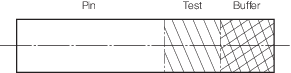
Figure 10.4.2 Buffer and test piece location
for pins
4.6.8 Manufacturers intending to supply fittings in the machined condition are to submit
detailed drawings for approval by LR. Machining of Kenter shackles must result in a
fillet radius of a minimum of 3 per cent of the nominal diameter.
4.7 Identification
4.7.1 Each fitting is to be permanently marked with the following information:
- identification number, cast number or other marking which will enable the
full history of the casting to be traced;
- manufacturer’s name or trade mark;
- LR or Clasifications Register, the abbreviated name of LR's local office, and
number of certificate;
- personal stamp of Surveyor responsible for inspection;
- date of final inspection; and
- chain grade.
4.7.2 Where small casting/forging fittings are manufactured in large numbers, modified
arrangements for identification may be specially agreed with the Surveyor.
4.8 Documentation
4.8.1 A complete Inspection and Testing Report in booklet form is to be provided by the
manufacturer for each order. This booklet include all dimensional checks, test and
inspection reports, NDE reports, process records and example photographs of
components positioned in furnaces, as well as any non-conformity, corrective action
and repair work.
4.8.2 Each type of fitting must be covered by separate certificates.
4.8.3 All documents, including reports and appendices, are to contain a reference to the
relevant certificate number.
4.8.4 The manufacturer is responsible for storing all the documentation in a safe and
retrievable manner for a period of at least 10 years.
4.9 Certification
|