
Section
3 Offshore Mooring chain cables
3.1 Scope
3.1.1 Provision is made in this Section for five grades, R3, R3S, R4, R4S and R5,
of stud link chain and studless flash butt welded chain cable intended for offshore
mooring applications such as mooring of mobile offshore units, mooring of floating
production units, offshore loading systems and gravity based structures during
fabrication. Special consideration will be given to the use of grades outside the
existing scope.
3.1.2 Design of stud link chain cables must be to a recognised Standard, such as
ISO 1704. For studless chain the shape and dimensions are to comply with the
requirements of this Section. Non-Standard designs of chain are to be subject to special
consideration, and may require a fatigue analysis and tests to confirm relevant
performance.
3.1.3 In addition,
chain cable conforming to the requirements of the current edition
of API specification 2F is acceptable provided that it has been manufactured,
inspected and tested under survey by LR, and that the bar stock has
also been certified by LR in accordance with Ch 3, 9 Bars for welded chain cables.
3.1.4 The studless link chain is generally expected to be deployed only once, being intended
for long-term mooring applications with a pre-determined service life.
3.2 Manufacture
3.2.1 All grades of chain cable and fittings are to be manufactured by approved
procedures at works approved by LR. A list of approved manufacturers for offshore
mooring chain cables is published separately by LR.
3.2.2 Approval
is confined to a single works and is limited to one grade of cable
made from bar from a nominated and approved supplier. Separate approvals
are required if steel bar is supplied from more than one works and
for other grades of cable, see also
Ch 3, 9 Bars for welded chain cables.
3.2.3 Details
of the method of manufacture and the specification of the steel, are
to be submitted.
3.2.4 Offshore
mooring chains are to be made in continuous lengths by flash-butt
welding.
3.2.5 Bar material may be heated by electric resistance, induction or in a
furnace. For electrical resistance heating or induction heating, the process is to be
controlled by an optical heat sensor. For furnace heating, thermocouples in close
proximity to the bars are to be used for control and the temperature is to be
continuously recorded. In both cases, the controls are to be checked at least once every
eight hours and records taken.
3.2.6 The following
welding parameters (as approved in the weld procedure) are to be controlled
during welding of each link:
-
platen motion;
-
current as a function
of time; and
-
hydraulic pressure.
The controls are to be checked at least once every four hours and records
taken.
3.2.7 The records
of bar heating, flash-butt welding and heat treatment are to be made
available to the Surveyor when required.
3.2.8 As far as
practicable, consecutive links in all chain cable should originate
from a single batch of bar stock (see
Ch 3, 9.6 Mechanical tests 9.6.1) and indicating marks should
be stamped on the final link formed from one batch and the first link
formed from a separate batch.
3.3 Studs
3.3.1 The studs are to be made of steel corresponding to that of the chain or in
compliance with a specification approved by LR. In general, the carbon content should
not exceed 0,23 per cent if the studs are to be welded in place.
3.3.2 Studs may
be welded into grade R3 and R3S chains. The welding of studs into
grade R4, R4S and R5 chain is not permitted unless specially approved.
3.3.5 Where plastic
straining is used to set studs, the applied load is not to be greater
than that qualified in approval tests. The combined effect of shape
and depth of the impression of the stud in the link is not to cause
any harmful notch effect or stress concentration.
3.4 Heat treatment of completed chain cables
3.4.1 The chain
is to be normalised, normalised and tempered or quenched and tempered
in accordance with the specification approved by LR.
3.4.2 The chains are to be heat treated in a continuous furnace; batch heat
treatment is not permitted unless specially approved.
3.4.3 The temperature
and time, or temperature and chain speed, are to be controlled and
continuously recorded.
3.4.4 Heat treatment is to be carried out prior to the proof loading, breaking
tests and sample mechanical tests.
3.4.5 The heat treatment furnace is to be properly constructed, efficiently
maintained and has adequate means of temperature control. Calibration of furnaces is to
be verified by measurement and recording of a calibration test piece with dimensions
equivalent to the maximum size of link manufactured.
3.5 Testing of completed chain cables
3.5.1 All chain cables are to be subjected to proof load tests, non-destructive
examination, sample break load tests and sample mechanical tests after final heat
treatment in the presence of a Surveyor. In addition to the requirements stated in this
Chapter, attention must be given to any relevant statutory requirements of the National
Authority of the country in which the ship is to be registered.
3.5.2 The chain is to be shot or sand-blasted prior to testing in order to ensure that its
surfaces are free from scale, paint or other coating for inspection and have a suitably
prepared surface in accordance with the NDE standard applied.
3.6 Proof load tests and non-destructive examination
3.6.1 The entire length of chain cable is to be subjected to a proof loading
test at a Proving Establishment recognised by LR. A list of recognised Proving
Establishments is published in the Class Direct section of LR’s website,
http://www.lr.org. The chain cable is to withstand the load given inCh 10, 3.6 Proof load tests and non-destructive examination 3.6.1 for the appropriate grade and size of cable.
Table 10.3.1 Test loads for mooring chain
cables
| Nominal diameter
d
|
Grade R3
|
Grade R3S
|
Grade R4
|
Grade R4S
|
Grade R5
|
| Proof test load
|
Break test load
|
Proof test load
|
Break test load
|
Proof test load
|
Break test load
|
Proof test load
|
Break test load
|
Proof test load
|
Break test load
|
| Stud link
chain
|
Studless chain
|
Stud link
chain
|
Studless
chain
|
Stud link chain
|
Studless
chain
|
Stud link chain
|
Studless
chain
|
Stud link
chain
|
Studless chain
|
| mm
|
kN
|
kN
|
kN
|
kN
|
kN
|
kN
|
kN
|
kN
|
kN
|
kN
|
kN
|
kN
|
kN
|
kN
|
kN
|
| 50
|
1480
|
1480
|
2230
|
1800
|
1740
|
2490
|
2160
|
1920
|
2740
|
2400
|
2130
|
3040
|
2510
|
2230
|
3200
|
| 52
|
1594
|
1594
|
2402
|
1939
|
1874
|
2682
|
2327
|
2068
|
2952
|
2585
|
2295
|
3275
|
2704
|
2402
|
3447
|
| 54
|
1712
|
1712
|
2580
|
2083
|
2013
|
2881
|
2499
|
2222
|
3170
|
2777
|
2465
|
3517
|
2904
|
2580
|
3703
|
| 56
|
1834
|
1834
|
2764
|
2231
|
2156
|
3086
|
2677
|
2380
|
3396
|
2974
|
2640
|
3768
|
3111
|
2764
|
3966
|
| 58
|
1960
|
1960
|
2953
|
2383
|
2304
|
3297
|
2860
|
2542
|
3628
|
3178
|
2820
|
4025
|
3323
|
2953
|
4237
|
|
|
|
|
|
|
|
|
|
|
|
|
|
|
|
|
|
| 60
|
2089
|
2089
|
3147
|
2540
|
2455
|
3514
|
3048
|
2710
|
3867
|
3387
|
3006
|
4290
|
3542
|
3147
|
4516
|
| 62
|
2221
|
2221
|
3347
|
2701
|
2611
|
3737
|
3242
|
2881
|
4112
|
3602
|
3196
|
4562
|
3767
|
3347
|
4802
|
| 64
|
2357
|
2357
|
3551
|
2867
|
2771
|
3965
|
3440
|
3058
|
4364
|
3822
|
3392
|
4841
|
3997
|
3551
|
5096
|
| 66
|
2496
|
2496
|
3761
|
3036
|
2935
|
4200
|
3643
|
3238
|
4621
|
4048
|
3593
|
5127
|
4233
|
3761
|
5397
|
| 68
|
2639
|
2639
|
3976
|
3209
|
3102
|
4440
|
3851
|
3423
|
4885
|
4279
|
3798
|
5420
|
4475
|
3976
|
5706
|
|
|
|
|
|
|
|
|
|
|
|
|
|
|
|
|
|
| 70
|
2785
|
2785
|
4196
|
3387
|
3274
|
4685
|
4064
|
3613
|
5156
|
4516
|
4008
|
5720
|
4723
|
4196
|
6021
|
| 73
|
3010
|
3010
|
4535
|
3660
|
3538
|
5064
|
4392
|
3904
|
5572
|
4881
|
4331
|
6182
|
5104
|
4535
|
6507
|
| 76
|
3242
|
3242
|
4884
|
3942
|
3811
|
5454
|
4731
|
4205
|
6001
|
5257
|
4665
|
6658
|
5498
|
4884
|
7009
|
| 78
|
3400
|
3400
|
5123
|
4135
|
3997
|
5720
|
4962
|
4411
|
6295
|
5514
|
4893
|
6984
|
5766
|
5123
|
7351
|
| 81
|
3643
|
3643
|
5490
|
4431
|
4283
|
6130
|
5317
|
4726
|
6745
|
5908
|
5243
|
7484
|
6179
|
5490
|
7877
|
|
|
|
|
|
|
|
|
|
|
|
|
|
|
|
|
|
| 84
|
3893
|
3893
|
5866
|
4735
|
4577
|
6550
|
5682
|
5051
|
7208
|
6313
|
5603
|
7997
|
6602
|
5866
|
8418
|
| 87
|
4149
|
4149
|
6252
|
5046
|
4878
|
6981
|
6056
|
5383
|
7682
|
6729
|
5972
|
8523
|
7037
|
6252
|
8971
|
| 90
|
4412
|
4412
|
6647
|
5365
|
5187
|
7422
|
6439
|
5723
|
8167
|
7154
|
6349
|
9062
|
7482
|
6647
|
9539
|
| 92
|
4590
|
4590
|
6916
|
5582
|
5396
|
7722
|
6699
|
5954
|
8497
|
7443
|
6606
|
9428
|
7784
|
6916
|
9924
|
| 95
|
4862
|
4862
|
7326
|
5913
|
5716
|
8180
|
7096
|
6307
|
9001
|
7884
|
6997
|
9987
|
8246
|
7326
|
10512
|
|
|
|
|
|
|
|
|
|
|
|
|
|
|
|
|
|
| 97
|
5047
|
5047
|
7604
|
6138
|
5933
|
8490
|
7365
|
6547
|
9343
|
8184
|
7263
|
10366
|
8559
|
7604
|
10911
|
| 100
|
5328
|
5328
|
8028
|
6480
|
6264
|
8964
|
7776
|
6912
|
9864
|
8640
|
7668
|
10944
|
9036
|
8028
|
11520
|
| 102
|
5519
|
5519
|
8315
|
6712
|
6488
|
9285
|
8054
|
7159
|
10217
|
8949
|
7942
|
11336
|
9359
|
8315
|
11932
|
| 105
|
5809
|
5809
|
8753
|
7065
|
6829
|
9773
|
8478
|
7536
|
10754
|
9420
|
8360
|
11932
|
9851
|
8753
|
12560
|
| 107
|
6005
|
6005
|
9048
|
7304
|
7060
|
10103
|
8764
|
7790
|
11118
|
9738
|
8643
|
12335
|
10184
|
9048
|
12984
|
|
|
|
|
|
|
|
|
|
|
|
|
|
|
|
|
|
| 111
|
6404
|
6404
|
9650
|
7789
|
7529
|
10775
|
9347
|
8308
|
11856
|
10385
|
9217
|
13154
|
10861
|
9650
|
13847
|
| 114
|
6709
|
6709
|
10109
|
8159
|
7887
|
11287
|
9791
|
8703
|
12420
|
10879
|
9655
|
13780
|
11378
|
10109
|
14506
|
| 117
|
7018
|
7018
|
10574
|
8535
|
8251
|
11807
|
10242
|
9104
|
12993
|
11380
|
10100
|
14415
|
11902
|
10574
|
15174
|
| 120
|
7331
|
7331
|
11047
|
8916
|
8619
|
12334
|
10700
|
9511
|
13573
|
11889
|
10551
|
15059
|
12434
|
11047
|
15852
|
| 122
|
7542
|
7542
|
11365
|
9173
|
8868
|
12690
|
11008
|
9785
|
13964
|
12231
|
10855
|
15493
|
12792
|
11365
|
16308
|
|
|
|
|
|
|
|
|
|
|
|
|
|
|
|
|
|
| 124
|
7755
|
7755
|
11686
|
9432
|
9118
|
13048
|
11319
|
10061
|
14358
|
12576
|
11161
|
15930
|
13153
|
11686
|
16768
|
| 127
|
8078
|
8078
|
12171
|
9824
|
9497
|
13591
|
11789
|
10479
|
14955
|
13099
|
11626
|
16592
|
13700
|
12171
|
17466
|
| 130
|
8404
|
8404
|
12663
|
10221
|
9880
|
14139
|
12265
|
10903
|
15559
|
13628
|
12095
|
17262
|
14253
|
12663
|
18171
|
| 132
|
8623
|
8623
|
12993
|
10488
|
10138
|
14508
|
12585
|
11187
|
15965
|
13984
|
12411
|
17713
|
14625
|
12993
|
18645
|
| 137
|
9178
|
9178
|
13829
|
11162
|
10790
|
15441
|
13395
|
11906
|
16992
|
14883
|
13209
|
18852
|
15565
|
13829
|
19844
|
|
|
|
|
|
|
|
|
|
|
|
|
|
|
|
|
|
| 142
|
9741
|
9741
|
14677
|
11847
|
11452
|
16388
|
14216
|
12637
|
18033
|
15796
|
14019
|
20008
|
16520
|
14677
|
21061
|
| 147
|
10311
|
10311
|
15536
|
12540
|
12122
|
17347
|
15048
|
13376
|
19089
|
16720
|
14839
|
21179
|
17487
|
15536
|
22294
|
| 152
|
10887
|
10887
|
16405
|
13241
|
12800
|
18317
|
15890
|
14124
|
20156
|
17655
|
15669
|
22363
|
18464
|
16405
|
23540
|
| 157
|
11469
|
11469
|
17282
|
13949
|
13484
|
19297
|
16739
|
14879
|
21234
|
18599
|
16507
|
23559
|
19452
|
17282
|
24799
|
| 162
|
12056
|
12056
|
18166
|
14663
|
14174
|
20284
|
17596
|
15641
|
22320
|
19551
|
17351
|
24764
|
20447
|
18166
|
26068
|
|
|
|
|
|
|
|
|
|
|
|
|
|
|
|
|
|
| 167
|
12647
|
12647
|
19056
|
15381
|
14869
|
21278
|
18458
|
16407
|
23414
|
20508
|
18201
|
25977
|
21448
|
19056
|
27345
|
| 172
|
13240
|
13240
|
19950
|
16103
|
15566
|
22276
|
19324
|
17177
|
24513
|
21471
|
19055
|
27196
|
22455
|
19950
|
28628
|
| 177
|
13836
|
13836
|
20847
|
16827
|
16267
|
23278
|
20193
|
17949
|
25615
|
22437
|
19912
|
28420
|
23465
|
20847
|
29915
|
| 182
|
14433
|
14433
|
21746
|
17553
|
16968
|
24282
|
21064
|
18723
|
26720
|
23404
|
20771
|
29645
|
24477
|
21746
|
31205
|
| 187
|
15029
|
15029
|
22646
|
18279
|
17670
|
25286
|
21935
|
19498
|
27825
|
24372
|
21630
|
30871
|
25489
|
22646
|
32496
|
|
|
|
|
|
|
|
|
|
|
|
|
|
|
|
|
|
| 192
|
15626
|
15626
|
23544
|
19004
|
18371
|
26289
|
22805
|
20271
|
28929
|
25339
|
22488
|
32096
|
26500
|
23544
|
33785
|
| 197
|
16220
|
16220
|
24440
|
19727
|
19070
|
27290
|
23673
|
21043
|
30029
|
26303
|
23344
|
33317
|
27509
|
24440
|
35071
|
| 202
|
16813
|
16813
|
25332
|
20448
|
19766
|
28286
|
24537
|
21811
|
31126
|
27264
|
24196
|
34534
|
28513
|
25332
|
36351
|
| 207
|
17401
|
17401
|
26220
|
21164
|
20459
|
29277
|
25397
|
22575
|
32216
|
28219
|
25044
|
35744
|
29512
|
26220
|
37625
|
| 210
|
17753
|
17753
|
26749
|
21591
|
20872
|
29868
|
25910
|
23031
|
32867
|
28788
|
25550
|
36465
|
30108
|
26749
|
38385
|
|
|
|
|
|
|
|
|
|
|
|
|
|
|
|
|
|
| Grade R3
|
|
|
|
|
|
|
|
|
|
|
|
|
|
|
| Proof test load
|
Stud link chain
|
0,0148d
2 (44 – 0,08d)
|
|
|
|
|
|
|
|
|
|
|
|
Studless chain
|
0,0148d2 (44 – 0,08d)
|
|
|
|
|
|
|
|
|
|
| Break test load
|
|
|
0,0223d2 (44 – 0,08d)
|
|
|
|
|
|
|
|
|
|
| Grade R3S
|
|
|
|
|
|
|
|
|
|
|
|
|
|
|
| Proof test load
|
Stud link chain
|
0.0180d
2 (44 – 0,08d)
|
|
|
|
|
|
|
|
|
|
|
|
Studless chain
|
0,0174d
2 (44 – 0,08d)
|
|
|
|
|
|
|
|
|
|
| Break test load
|
|
|
0,0249d
2 (44 – 0,08d)
|
|
|
|
|
|
|
|
|
|
| Grade R4
|
|
|
|
|
|
|
|
|
|
|
|
|
|
|
| Proof test load
|
Stud link chain
|
0,0216d
2 (44 – 0,08d)
|
|
|
|
|
|
|
|
|
|
|
|
Studless chain
|
0,0192d
2 (44 – 0,08d)
|
|
|
|
|
|
|
|
|
|
| Break test load
|
|
|
0,0274d
2 (44 – 0,08d)
|
|
|
|
|
|
|
|
|
|
| Grade R4S
|
|
|
|
|
|
|
|
|
|
|
|
|
|
|
| Proof test load
|
Stud link chain
|
0,0240d
2 (44 – 0,08d)
|
|
|
|
|
|
|
|
|
|
|
|
Studless chain
|
0,0213d
2 (44 – 0,08d)
|
|
|
|
|
|
|
|
|
|
| Break test load
|
|
0,0304d
2 (44 – 0,08d)
|
|
|
|
|
|
|
|
|
|
| Grade R5
|
|
|
|
|
|
|
|
|
|
|
|
|
|
| Proof test load
|
Stud link chain
|
0,0251d
2 (44 – 0,08d)
|
|
|
|
|
|
|
|
|
|
|
|
Studless chain
|
0,0223d
2 (44 – 0,08d)
|
|
|
|
|
|
|
|
|
|
| Break test load
|
|
0,0320d
2 (44 – 0,08d)
|
|
|
|
|
|
|
|
|
|
3.6.2 Care should be taken to obtain a uniform stress distribution in the
links being tested.
3.6.3 On completion of the proof load test, each link is to be visually
examined and is to be free from significant defects such as mill defects, surface
cracks, dents and cuts, especially where gripped by clamping dies during flash butt
welding. Studs are to be securely fastened and any burrs, irregularities and rough
edges are to be removed by careful grinding. In order to ensure adequate inspection,
the chain is to be positioned to facilitate access to all surfaces.
3.6.4 All flash butt welds, including the area gripped by the clamping dies on every link,
plus 10 per cent of links on all accessible surfaces, are to be examined by magnetic
particle inspection in accordance with standards recognized by LR, using wet
continuous fluorescent magnetization technique. Non-fluorescent techniques can be
accepted in special cases where the standard inspection procedures are impractical.
The inspected area is to be free from cracks, lack of fusion, gross porosity, and
any imperfections with the following maximum allowable dimensions:
- relevant linear indications exceeding 1,6 mm in transverse direction;
- relevant linear indications exceeding 3,2 mm in longitudinal direction;
- relevant non-linear indications exceeding 4,8 mm.
3.6.5 Surface defects in the region of the flash butt welds may be removed by
grinding, provided that the depth of grinding does not exceed five per cent of the
link diameter and is smoothly contoured into the surrounding material. The final
dimensions are still to conform with the agreed standard.
3.6.6 All flash butt welds on every link are also to be examined by ultrasonic testing in
accordance with standards recognised by LR using appropriate scanning techniques
designed to detect all expected defects, including any defects within the relevant
fusion zones. The flash butt weld must be free from defects causing ultrasonic back
reflections equal to or greater than the calibration standard. The single probe
technique has limitations as far as testing of the central region is concerned and
the flash butt weld imperfections such as flat spots may have poor reflectivity.
Where it is deemed necessary, detectability of imperfections may need to be carried
out by using a tandem technique, TOFD (Time-of-flight diffraction) or PAUT (phased
array ultrasonic testing).
3.6.7 Stud welds, if used, are to be visually inspected. The toes of the fillets are to
have a smooth transition to the link with no undercuts exceeding 1,0 mm. In
addition, at least 10 per cent of the stud welds distributed through the length is
to be magnetic particle or dye penetrant tested in accordance with standards
recognised by LR. Cracks, lack of fusion or gross porosity are not acceptable. If
defects are found, testing is to be extended to all stud welds in that length of
chain.
3.6.9 In the event that two or more links break during the proof load testing, the proof
loaded length is to be rejected.
3.6.10 In all cases when a link breaks during the proof load testing, a thorough examination
of all broken links is to be made to determine the cause of failure and, after
evaluation, LR will consider the extent of cable which is to be rejected and also
the possibility that similar factors to those which caused the failure may also be
present in other parts of the cable, or other chain cables, i.e.:
- Where multiple chains are produced simultaneously, it is recognised that the
preceding flash butt welded link and subsequent flash butt welded link will be
on an alternative chain length or the other end of the chain length. In such
cases, LR may require that two additional break tests are to be taken from the
lengths of chain that include the preceding and subsequent welded links.
- If the investigation identifies defects in the flash butt weld or a lower
strength flash butt weld is found, additional NDE is to be carried out to
identify if other links are affected. A full assessment of the flash butt
welding machine it to be carried out, together with assessment of the condition
of the bar ends prior to welding.
- The Surveyor is to be advised in advance of all examinations, with reasonable
notice being given.
3.7 Dimensional inspection
3.7.1 After proof testing, the entire chain is to be checked for length, five
links at a time with an overlap of two links, which is to include the first five
links, to ensure that the chain meets the tolerances given in Ch 10, 3.7 Dimensional inspection 3.7.3. The measurements are to be made while the chain is
loaded to about 5-10 per cent of the minimum proof load.
3.7.2 The links held in the end blocks may be excluded from these
measurements.
3.7.4 If the length over five links is less than the nominal, the chain may be
stretched by loading above the specified proof test load provided that the applied
load is not greater than ten per cent above the proof test load, and that only
random lengths of the chain need to be stretched.
3.7.5 Checks of all other dimensions are to be made on at least five per cent
of the links in the cable.
3.7.6 A manufacturing tolerance on all other dimensions of ±2,5 per cent is acceptable
subject to all parts fitting properly together.
3.7.7 The form and proportions of links are to be in accordance with ISO1704,
see
Figure 10.2.2 Common link. Link tolerances are to be in accordance
with Ch 10, 3.7 Dimensional inspection 3.7.4 to
Ch 10, 3.7 Dimensional inspection 3.7.10.
The negative tolerance on the nominal diameter measured at the crown is not to exceed
the following:
- Minus 1 mm when dc < 40 mm
- Minus 2 mm when 40 mm < dc < 84 mm
- Minus 3 mm when 84 mm < dc < 122 mm
- Minus 4 mm when 122 mm < dc < 152 mm
- Minus 6 mm when 152 mm < dc < 184 mm
- Minus 7,5 mm when 184 mm < dc < 222 mm
For diameters of 20 mm or greater, the plus tolerance on the diameter at the crown
measured perpendicular to the plane of the link, dp, is not to exceed 5
per cent. For diameters less than 20 mm, the plus tolerance is to be agreed between
the chain manufacturer and bar material supplier.
3.7.8 The cross-sectional area at the crown is to be calculated using the average of the
measured diameters, which are to be taken from at least two locations approximately
90 degrees apart. The cross-sectional area at the crown is to have no negative
tolerance.
3.7.9 The diameter measured at locations other than the crown is to have no negative
tolerance. For diameters of 20 mm or greater, the plus tolerance may be up to 5 per
cent of the nominal diameter except at the butt weld where it is to be in accordance
with the manufacturer’s specification, which is to be agreed by LR. For diameters
less than 20 mm, the plus tolerance is to be agreed between the chain manufacturer
and bar material supplier.
3.7.10 If any link fails to meet the above dimensional tolerance requirements,
measurements are to be made on 20 more links on each side of the incorrect one. If
failure to meet any particular dimensional requirements occurs in more than two of
the measured links, then all the links are to be dimensionally checked.
3.7.11 Should any link be found to be defective or fail to meet the dimensional
tolerance requirements or if a five link length of chain exceeds the specified
tolerance, the unsatisfactory links are to be removed from the chain and connecting
common links complying with the requirements of Ch 10, 3.10 Connecting common links or substitute links
inserted in their places. Proposals for other methods of repair must be subject to
approval by LR and the purchaser. Weld repair of chain is not permitted.
3.7.13 The chain is then to be subjected to a further proof load test and
re-examined.
3.7.14 The number of connecting common links which may be used to replace
defective links is not to exceed three in any 100m length of chain. The number and
type of joining shackles which may be used are to be subject to the written
agreement of the end user.
3.7.15 All measurements are to be made on links selected by the Surveyor and are to be
carried out to the Surveyor’s satisfaction.
3.7.16 For stud link chain, studs are to be located in the links centrally, and at right
angles to the sides of the link, although the studs of the final link at each end of
any length may also be located off-centre to facilitate the insertion of the joining
shackle. The tolerances in accordance with Table 10.3.2 Stud link chain cable common
link tolerances are
acceptable provided that the stud fits snugly and its ends lie flush against the
inside of the link.
3.7.17 Chain dimensions are to be recorded and the information retained on file.
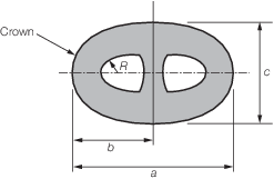
Table 10.3.2 Stud link chain cable common
link tolerances
| The internal link radii (R) and
external radii should be uniform
|
|
| Designation
|
Description
|
Nominal
dimension of the link
|
Minus
tolerance
|
Plus tolerance
|
|
a
|
Link
length
|
6d
|
0,15d
|
0,15d
|
|
b
|
Link half
length
|
a*/2
|
0,10d
|
0,10d
|
|
c
|
Link
width
|
3,6d
|
0,09d
|
0,09d
|
|
e
|
Stud angular
misalignment
|
0
degrees
|
4
degrees
|
4
degrees
|
|
R
|
Inner
radius
|
0,65d
|
0
|
—
|
| Symbols
|
|
d
|
= |
nominal diameter of chain |
|
a* |
= |
actual link length |
|
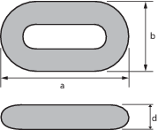
Table 10.3.3 Studless link chain cable common link tolerances
| The internal link radii (R) and external radii
should be uniform
|
|
| Designation
|
Description
|
Nominal dimension of the
link
|
Minus tolerance
|
Plus tolerance
|
|
a
|
Link length
|
6d
|
0,15d
|
0,15d
|
|
b
|
Link width
|
3,35d
|
0,09d
|
0,09d
|
|
R
|
Inner radius
|
0,60d
|
0
|
—
|
| Symbols
|
|
d
|
= |
nominal diameter of chain |
|
Note Other dimensional ratios are subject to special
approval.
|
3.8 Breaking load tests
3.8.1 In addition to the requirements of Ch 10, 3.6 Proof load tests and non-destructive examination 3.6.1, three link samples are to be selected by the
Surveyors from the completed chain for breaking tests. The number of tests required
is to be in accordance with Ch 10, 3.8 Breaking load tests 3.8.5. Extra links are to be provided for the mechanical
tests detailed in Ch 10, 3.9 Mechanical tests 3.9.1. All test links are to be made as part of the chain
cable and are to be heat treated with it. These may be removed from the cable prior
to heat treatment provided that each sample is heat treated with, and in the same
manner as, the chain it represents prior to selection of the mechanical test
specimens. They are to be properly identified with the length of chain they
represent.
3.8.2 Breaking test specimens are to withstand the load given in Table 10.3.1 Test loads for mooring chain
cables for the appropriate grade and size of
cable for a period of 30 seconds. The specimen is considered to have passed this
test if it has shown no sign of fracture and must not crack in the flash butt weld
after application of the required load.
3.8.3 If a breaking test specimen fails, two further specimens are to be cut
from the same sampling length and both are to be subjected to the breaking test
load. If one of the re-test specimens fails the length is to be rejected. All the
broken links are to be subjected to an investigation into the cause of failure. LR
will then decide which lengths of chain can be accepted and on further action.
3.8.4 For chain diameters over 100 mm, alternative break-test proposals to the
above break-test will be considered whereby a one link specimen is used.
Alternatives are to be approved by LR; every heat is to be represented, the test
frequency is to be in accordance with Table 10.3.4 Frequency of break and
mechanical tests, and it is to be demonstrated that the
alternative test represents an equivalent load application to the three link
test.
3.8.5 For large diameter cables where the required breaking load is greater
than the capacity of the testing machines, special consideration will be given to
acceptance of an alternative testing procedure.
Table 10.3.4 Frequency of break and
mechanical tests
| Nominal
chain diameter mm
|
Maximum
sampling interval m (See Note)
|
| Min. — 48
|
91
|
| 49
— 60
|
110
|
| 61
— 73
|
131
|
| 74
— 85
|
152
|
| 86
— 98
|
175
|
| 99
— 111
|
198
|
| 112 — 124
|
222
|
| 125 — 137
|
250
|
| 138 — 149
|
274
|
| 150 — 162
|
297
|
| 163 — 175
|
322
|
| 176 — 186
|
346
|
| 187 — 198
|
370
|
| 199 —
210
|
395
|
| 211 — 222
|
420
|
Note If the sampling interval contains links made from
more than one cast, extra break and mechanical tests are
required so that tests are made on every cast.
|
3.9 Mechanical tests
3.9.1 One tensile and three sets of Charpy V-notch impact test specimens are
to be taken from links cut from the heat treated and proof loaded chain at intervals
no greater than those indicated in Table 10.3.4 Frequency of break and
mechanical tests provided that every cast
is sampled. The tensile specimen and one set of impact specimens are to be taken
from the side of the link opposite the weld. One set of impact test specimens is to
have the notches positioned at the centre of the flash butt weld and the third set
is to be taken from the bend. All the specimens are to be taken from positions in
accordance with Figure 10.3.2 Sampling of chain
links.
3.9.2 The frequency of testing at the link bends may be reduced at the
discretion of LR provided it can be verified that the required toughness is achieved
consistently.
3.9.4 If the tensile test requirements are not achieved, two further specimens
from the same sample are to be tested. The related length of chain will be
considered acceptable if both re-test specimens meet the requirements but failure of
either of the re-test specimens will result in rejection of the sampling length of
chain represented by the tests.
3.9.5 If the impact test requirements are not achieved, re-tests may be
carried out in accordance with Ch 2, 1.4 Re-testing procedures. Failure to meet the re-test
requirements will result in rejection of the sampling length of chain represented by
the tests.
3.9.6 A grain size determination must be made for the final product. The austenitic grain
size for R3, R3S, R4, R4S and R5 is to be 6 or finer in accordance with ASTM E112 or
equivalent grain size index in accordance to ISO 643. Measurements for circular
sections are to be taken at surface, at one-third of the radius and centre for the
base material, HAZ and weld.
3.9.7 Hardness tests are to be carried out on finished chain. The frequency and locations
are to be agreed with LR. The recorded values are for information only and used as
an additional check to verify that the heat treatment process has been stable during
the chain production.
3.9.8 The mass per unit length of stud link mooring cable is to comply with
Table 10.3.6 Mass per unit length of stud
link chain cable.

Figure 10.3.2 Sampling of chain
links
Table 10.3.5 Mechanical properties of chain
cable materials
| Grade
|
Yield stress
N/mm2 minimum
|
Tensile strength
N/mm2
|
Elongation % minimum
|
Reduction of area % minimum
(See Note 3)
|
Charpy V-notch impact tests
|
| Test
temperature ºC
|
Average
energy J minimum
|
Average
energy flash butt weld J minimum
|
| R3
|
410 (See Note 1)
|
690 minimum (See Note 1)
|
17
|
50
|
0
|
60
|
50
|
|
|
|
–20 (See Note 2)
|
40
|
30
|
| R3S
|
490 (See Note 1)
|
770 minimum (See Note 1)
|
15
|
50
|
0
|
65
|
53
|
|
|
|
–20 (See Note 2)
|
45
|
33
|
| R4
|
580
(See Note 1)
|
860 minimum (See Note 1)
|
12
|
50
|
–20
|
50
|
36
|
| R4S
(See Note 4)
|
700 (See Note 1)
|
960
(See Note 1)
|
12
|
50
|
–20
|
56
|
40
|
| R5 (See
Note 4)
|
760 (See
Note 1)
|
1000
(See Note 1)
|
12
|
50
|
–20
|
58
|
42
|
Note
1. The ratio of yield strength
to tensile strength should be 0,92 maximum unless specially
approved.
Note
2. Testing may be carried out
at either 0°C or –20°C.
Note
3. For cast fittings, the
minimum values for reduction of area are to be 40% for
Grades R3 and R3S and 35% for Grades R4, R4S and R5.
Note
4. The aim maximum hardness for
Grade R4S is to be HB330, and for Grade R5 is to be
HB340.
|
Table 10.3.6 Mass per unit length of stud
link chain cable
| Nominal chain diameter
(mm)
|
Mass per unit length
0,0219d
2 (kg/m)
|
| 50
|
55
|
| 55
|
66
|
| 60
|
79
|
| 65
|
93
|
| 70
|
107
|
| 75
|
123
|
| 80
|
140
|
| 85
|
158
|
| 90
|
177
|
| 95
|
198
|
| 100
|
219
|
| 105
|
241
|
| 110
|
265
|
| 115
|
290
|
| 120
|
315
|
| 125
|
342
|
| 130
|
370
|
| 135
|
399
|
| 140
|
429
|
| 145
|
460
|
| 150
|
490
|
| 155
|
526
|
| 160
|
561
|
| 165
|
596
|
| 170
|
633
|
| 175
|
671
|
| 180
|
710
|
| 185
|
750
|
| 190
|
791
|
| 195
|
833
|
| 200
|
876
|
| 205
|
920
|
| 210
|
966
|
| 222
|
1079
|
3.10 Connecting common links or substitute links
3.10.1 Single links
to connect lengths of heat treated chain cable or to substitute for
test links or defective links without the necessity for re-heat treatment
of the whole length of cable are to be made by the chain manufacturer
in accordance with an approved procedure. Separate approvals are required
for each grade of chain cable and tests are to be made on the maximum
size of chain for which approval is sought.
3.10.2 Manufacture
and heat treatment of the connecting common link is not to affect
the strength of the adjoining links. The temperature reached by these
links is nowhere to exceed 250°C.
3.10.4 Details
of the method of manufacture, including heat treatment, are to be
submitted for approval, together with the results of a series of tests
laid down by LR.
3.10.5 All links
involved in the approval tests are to be destroyed and are not to
be used as part of a chain cable.
3.10.9 Each connecting common link is to be stamped with the identification marks
listed in Ch 10, 3.11 Identification 3.11.1 plus a unique number for the link. The adjoining links are also to be
stamped.
3.11 Identification
3.11.1 Each length
of chain is to be permanently marked with the following:
-
LR and abbreviated
name of LR's local office issuing the certificate.
-
Certificate number
(this may be abbreviated provided it is stated in the certificate).
-
Grade and proof load
of chain.
3.11.2 The chain
is to be marked as follows:
-
at each end (the marking
should identify the leading and tail end of each chain),
-
at intervals not exceeding
100 m,
-
on all connecting
common links or shackles and the immediately adjacent links,
-
on the first and last
common link of each individual heat used in the continuous length.
3.11.3 All identification marks are to be made on the studs for stud link chain or, on the
outside of the straight part of the link, opposite the flash butt weld for studless
chain, and are to be permanent and legible throughout the expected service life of the
chain.
3.12 Documentation
3.12.1 A complete Chain Inspection and Testing Report, in booklet form, is to be
provided by the chain manufacturer for each continuous chain length, and for each order
for chain and fittings. It is to include all dimensional checks, test and inspection
reports, non-destructive test reports, process records, photographs (for fittings,
example photographs of components positioned in furnaces), as well as any
non-conformity, together with corrective action and repair work.
3.12.2 All documents,
including reports and appendices, are to contain a reference to the
relevant certificate number.
3.12.3 The chain
manufacturer is responsible for storing all the documentation in a
safe and retrievable manner for a period of at least 10 years.
3.13 Certification
3.13.1 An LR
certificate is to be issued for each continuous single length of chain,
and each type of fitting, see
Ch 1, 3.1 General.
3.13.2 Each test
certificate is to include the following particulars:
-
Purchaser’s
name and order number.
-
Description and dimensions.
-
Grade of chain cable.
-
Identification mark
which will enable the full history of the chain to be traced.
-
Chemical composition.
-
Details of heat treatment.
-
Mechanical test results.
-
Breaking test load.
-
Proof load.
-
The number and locations
of all connecting common links and all marked links.
|