
Section
2 Specific requirements for ship hull structure and machinery
2.1 Scope
2.1.2 The shipyard
and manufacturer’s works are to be assessed to give assurance
that they have the facilities, equipment, personnel and quality control
procedures to produce work of the required quality.
2.2 Welding consumables
2.2.1 Welding
consumables used for hull construction are to be approved in accordance
with Ch 11 Approval of Welding Consumables and are to be suitable
for the type of joint and grade of material to be welded.
2.2.2 Steel welding
consumable approvals, up to and including Grade Y40, and Y47, are
considered acceptable for hull construction in line with Table 11.1.1 Welding consumable grades
appropriate to structural and low temperature service steel grades in Chapter 11, Ch 12, 2.2 Welding variables 2.2.2 and the following:
-
Consumables up to
Grade Y are acceptable for welding steels up to 3 strength levels
below that for which the approval applies, e.g. a consumable with
approval grading 3Y is acceptable for welding EH36, EH32 and EH27S
higher tensile ship steels and grade E normal strength ship steel.
-
Consumables for Grade
Y40 are acceptable for welding steels up to two strength levels below
that for which the approval applies. Consumables for Grade Y47 are
acceptable for welding steels up to one strength level below that
for which the approval applies.
-
Consumables with an
approved impact toughness grading are acceptable for welding steels
with lower specified impact properties subject to (a) above, e.g.
a consumable with approval grading 3Y is acceptable for welding EH,
DH and AH materials.
-
For welding steels
of different grades or different strength levels, the welding consumables
may be of a type suitable for the lesser grade or strength being connected.
The use of a higher grade of welding consumable may be required at
discontinuities or other points of stress concentration.
2.2.3 In general,
the use of preheating and hydrogen controlled welding consumables
for welding of ship steels up to strength grade H40 is to be in accordance
with Table 13.2.1 Preheat and consumable
requirements for welding of carbon and carbon manganese steels up to strength grade
H40. The carbon
equivalent is to be calculated from the ladle analysis using the formula
given below:
|
Carbon equivalent
|
= |

|
Preheat and the use of low hydrogen controlled consumables
will be required for welding of steel grades higher than Grade H40.
Table 13.2.1 Preheat and consumable
requirements for welding of carbon and carbon manganese steels up to strength grade
H40
| Carbon equivalent C
eq
|
Preheat
|
Hydrogen controlled
consumables
|
|
C
eq equal to or less than 0,41%
|
Not required
|
Not required, see Note 3
|
|
C
eq above 0,41 but not exceeding 0,45%
|
Not required, see Notes 1 and
2
|
Required
|
|
C
eq greater than 0,45%
|
Required
|
Required
|
Note
2. Under conditions of high restraint or
low ambient temperature preheat may need to be applied.
Note
3. Hydrogen controlled consumables may
need to be considered for welding of
(a) Thicker materials (i.e. > 35 mm).
(b) Higher strength materials.
(c) Welds subject to high restraint.
|
2.2.5 All austenitic
stainless steel and duplex stainless steel welding consumables are
to be approved in accordance with the Ch 11 Approval of Welding Consumables and are suitable for welding the grades of material as shown
in Table 13.2.3 Welding of austenitic stainless
and duplex stainless steels - Consumable requirements.
Table 13.2.3 Welding of austenitic stainless
and duplex stainless steels - Consumable requirements
| Consumable approval
grade
|
Suitable for welding
material alloy grades
|
| Austenitic stainless steels
|
| 321
|
321
|
| 347
|
347 and 321
|
| Austenitic stainless steel – Low carbon
|
| 304L (see Note 3)
|
304L
|
| 304LN (see Note 3)
|
304LN and 304L
|
| 316L
|
316L and 304L
|
| 316LN
|
316LN, 316L, 304LN and 304L
|
| 317L
|
317L, 316LN, 316L, 304LN and
304L
|
| 317LN
|
317LN, 317L, 316LN, 316L, 304LN and
304L
|
| Super
austenitic stainless steels, see Note 2
|
| S31254
|
S31254 and N08904
|
| N08904
|
N08904
|
| Duplex
stainless steels, see Note 1
|
| S31260
|
S31260 and S31803
|
| S31803
|
S31803
|
| S32550
|
S32550
|
| S32750
|
S32750 and S32550
|
| S32760
|
S32760, S32550, S31260 and
S31803
|
| Stainless steels welded to carbon steels
|
| SS/CMn
|
Carbon steel to all steels in
Sections 1, 2 and 3
|
| Duplex/CMn
|
Carbon steel to all duplex stainless
steel in Section 4
|
Note
1. The use of a different welding
consumable grade from that of the base material may require
demonstration of acceptable corrosion properties.
Note
2. May be used for welding low carbon
austenitic grades provided measures are taken to prevent
solidification cracking from occurring.
Note
3. These are LR Grades and do not
correspond to any National or International Standards/Grades.
|
2.3 Welding procedure and welder qualifications
2.3.1 Welding
procedures and welder qualifications are to be tested and approved
in accordance with the requirements of Ch 12 Welding Qualifications.
2.4 Construction and workmanship
2.4.1 Weld preparations and openings may be formed by thermal cutting, machining
or chipping. Chipped surfaces that will not be subsequently covered by weld metal are to
be ground smooth.
2.4.2 Prior to welding, the alignment of plates and stiffeners forming part of
the hull structure is to be in accordance with the tolerances specified in the relevant
part of the Rules.
2.4.3 When welding from one side only, care is to be exercised to ensure the root
gap and fit up are in accordance with the approved welding procedure and the root is
properly fused.
2.4.4 Where it is proposed to use permanent backing strips, the intended locations
and welding procedures are to be submitted for consideration.
2.4.5 Temporary backing strips may be used provided they are in accordance with
approved welding procedures and are subsequently removed on completion of welding.
2.4.6 The outer surfaces of completed welds are to blend smoothly with the base
materials and provide a smooth transition and gradual change of section.
2.4.7 Weld joints in parts of oil engine structures that are stressed by the main
gas or inertia loads are to be designed as continuous full penetration welds. They are
to be arranged so that welds do not intersect, and that welding can be effected without
difficulty.
2.4.8 When modifications or repairs have been made which result in openings
having to be closed by welded inserts, particular care is to be given to the fit of the
insert and the welding sequence. The welding is also to be subject to non-destructive
examination.
2.4.9 Where welding of aluminium alloy is employed, the following additional
requirements are to be complied with so far as they are applicable:
-
Welding is to be performed by fusion welding using inert gas or
tungsten inert gas process or by the friction stir welding process. Where it is
proposed to use other welding processes, details are to be submitted for
approval.
-
The weld joint surfaces should be scratch brushed, preferably
immediately before welding, in order to remove oxide or adhering films of dirt,
filings, etc.
2.4.10 For steel grades EH47, EH47-BCA1 and EH47-BCA2, the following additional requirements
are applicable:
- When the ambient temperature is 5°C or less, or where moisture
resides on the surfaces to be welded, due care is to be taken to pre-heat the joint
to a minimum of 50°C, unless a higher pre-heat temperature is specified. Alternative
preheat requirements will be specially considered where Pcm of the material being
welded is less than or equal to 0,19 and the air temperature is below 5°C but above
0°C.
- The tack length may be 25 mm where Pcm of the material being
welded is less than or equal to 0,19.
2.5 Butt welds
2.5.1 Where the
ship hull is constructed of plates of different thicknesses, the thicker
plates are to be chamfered in accordance with the approved plans.
In all cases the chamfer is not to exceed a slope of 1 in 3 so that
the plates are of equal thickness at the weld seam. Alternatively,
if so desired, the width of the weld may be included as part of the
smooth taper to the thicker plate provided the difference in thickness
is not greater than 3 mm.
2.5.2 Where stiffening
members are attached by continuous fillet welds and cross completely
finished butt or seam welds, these are to be made flush in way of
the fillet weld. Similarly for butt welds in webs of stiffening members,
the butt weld is to be complete and generally made flush with the
stiffening member before the fillet weld is made. Where these conditions
cannot be complied with, a scallop is to be arranged in the web of
the stiffening member, see
Figure 13.2.1 Weld dimensions and types. Scallops are to be of such a size and in such a position
that a satisfactory weld can be made.
Figure 13.2.1 Weld dimensions and types
2.6 Lap connections
2.6.1 Overlaps
are generally not to be used to connect plates which may be subjected
to high tensile or compressive loading and alternative arrangements
are to be considered. However, where plate overlaps are adopted, the
width of the overlap is not to exceed four times, nor be less than
three times the thickness of the thinner plate and the joints are
to be positioned to allow adequate access for completion of sound
welds. The faying surfaces of lap joints are to be in close contact
and both edges of the overlap are to have continuous fillet welds.
2.7 Closing plates
2.7.1 For the
connection of plating to internal webs, where access for welding is
not practicable, the closing plating is to be attached by continuous
full penetration welds or by slot fillet welds to face plates fitted
to the webs. Slots are to have a minimum length of 90 mm and a minimum
width of twice the plating thickness, with well rounded ends. Slots
cut in plating are to be smooth and clean and are to be spaced not
more than 230 mm apart, centre to centre. Slots are not to be filled
with welding.
2.7.2 For the
attachment of rudder shell plating to the internal stiffening of the
rudder, slots are to have a minimum length of 75 mm and, in general,
a minimum width of twice the side plating thickness. The ends of the
slots are to be rounded and the space between them is not to exceed
150 mm.
2.8 Stud welding
2.8.1 Where permanent
or temporary studs are to be attached by welding to main structural
parts in areas subject to high stress, the proposed location of the
studs and the welding procedures adopted are to be approved.
2.9 Fillet welds
2.9.1 T-connections
are generally to be made by fillet welds on both sides of the abutting
plate, the dimensions and spacing of which are shown in Figure 13.2.1 Weld dimensions and types. Where the connection is
highly stressed, deep penetration or full penetration welding may
be required. Where full penetration welding is required, the abutting
plate may be required to be bevelled.
2.9.2 Where an
approved deep penetration procedure is used, the fillet leg length
calculated may be reduced by 15 per cent provided that the manufacturer
is able to meet the following requirements:
-
Use of a welding consumable approved for deep penetration welding in
accordance with Ch 11 Approval of Welding Consumables for either the ‘p’ or ‘T’ techniques.
-
Demonstrations by way of production weld testing that the minimum
required penetration depths (i.e. throat thicknesses) are maintained. This is to
be documented on a monthly basis by the manufacturer and be available to the
Surveyor.
2.9.3 The calculated
fillet leg length may be reduced by 20 per cent, provided that in
addition to the requirements of Ch 13, 2.9 Fillet welds 2.9.2.(a) and Ch 13, 2.9 Fillet welds 2.9.2.(b), the manufacturer is able to consistently
meet the following additional requirements:
-
The documentation
required in Ch 13, 2.9 Fillet welds 2.9.2.(b) is to be
completed and made available to the Surveyor upon request on a weekly
basis.
-
Suitable process selection
confirmed by satisfactory welding procedure tests covering both minimum
and maximum root gaps.
2.9.4 Where intermittent
welding is used, the welding is to be made continuous in way of brackets,
lugs and scallops and at orthogonal connections with other members.
2.10 Post-weld heat treatment
2.10.1 This section determines the requirements for post-weld stress relief heat treatment when
applied to ship structure and associated machinery.
2.10.2 Post-weld stress relief heat treatment is applied to improve resistance to
brittle fracture or fatigue performance. It is to be applied when the thickness limits
stated in Table 13.2.4 Post-weld stress relief heat treatment thickness limits are exceeded.
Table 13.2.4 Post-weld stress relief heat treatment thickness limits
| Typical
Application
|
Load Conditions
(See Note 1)
|
Material
Grade
(See Note 2)
|
Material
Thickness Limit (mm) (See Note 3)
|
| Ship
structure
|
Fatigue
non-critical / critical
|
Normal strength (A - E),
Higher strength (H27S - H40, [Excluding EH47])
|
150
|
| Ship
structure
|
Fatigue
non-critical / critical
|
Higher strength
(EH47)
|
100
|
| Machinery
|
Fatigue
non-critical
|
High strength (H42
- H69)
|
140
|
| Machinery
|
Fatigue
critical
|
High strength (H42
- H46)
|
100
|
| Machinery
|
Fatigue
critical
|
High strength (H50
- H69)
|
65
|
| Ship structure /
Machinery
|
Any
|
Other material
grades
|
Subject to special
consideration
|
Note 1. Fatigue analysis shall be approved by design appraisal according to
relevant rules for each application.
- Fatigue non-critical – Design assessment
confirms that there are cyclic stresses but the fatigue life is
reasonably greater than the design fatigue life and it is
anticipated that fatigue crack initiation and propagation are
unlikely to occur.
- Fatigue critical – Design assessment confirms
that there are cyclic stresses and the estimated fatigue life meets
the design requirements but it is not significantly higher. It is
anticipated that fatigue crack initiation and propagation are
likely to occur.
Note 2. Where steel grades based on national and international standards
are specially agreed for construction, they are to be procured from LR
approved works which hold current approval for the LR equivalent grade
and the same delivery condition as the steel to be procured.
Note 3. For all applications where material thickness is greater than 65 mm
(or greater than 100 mm for EH47), 100 per cent surface and volumetric
non-destructive examination of welds is required.
|
2.10.3 Post-weld heat treatment is to be applied to the following types of welded
construction:
-
Welding of steel castings where the thickness of the casting at the
weld exceeds 30 mm, except where castings are directly welded to the hull
structure.
-
Engine bedplates except for engine types where the bedplate as a
whole is not subjected to direct loading from the cylinder pressure. For these
types, only the transverse girder assemblies need to be stress relieved.
-
Welding of gear wheels.
-
Welding of gear cases associated with main or auxiliary engines,
see
Pt 5 Main and Auxiliary Machinery.
2.10.4 Consideration is to be given to applying post-weld heat treatment for all thicknesses of
complicated weld joints where there are high stress concentrations.
2.10.6 Special consideration may be given to omit the required post-weld heat treatment.
Evaluation is to be based on critical engineering assessment involving fracture
mechanics testing and proposals are to be submitted which include full details of the
application, materials, welding procedures, inspection procedures, design temperature
and stresses, fatigue loads and cycles. Evidence will be required to demonstrate that
the inspection techniques and procedures to be employed are able to detect flaws to the
sizes and tolerances (of length, through-wall height and through-wall position), as
determined from the fracture mechanics (and or fatigue) calculations. Alternative
procedures for the omission of post weld heat treatment will be subject to special
consideration.
2.11 Tolerances
2.11.1 Tolerances
after welding are to be in accordance with the relevant Part of the
Rules.
2.12 Non-destructive examination of steel
welds
2.12.1 All finished
welds are to be sound and free from cracks and substantially free
from lack of fusion, incomplete penetration, porosity and slag. The
surfaces of welds are to be reasonably smooth and substantially free
from undercut and overlap. Care is to be taken to ensure that the
specified dimensions of welds have been achieved and that both excessive
reinforcement and under-fill of welds is avoided.
2.12.2 Welds
forming part of the hull and superstructure may be coated with a thin
layer of protective primer prior to inspection provided it does not
interfere with inspection and is removed, if required by the Surveyor,
for closer interpretation of possible defective areas.
2.12.3 All welds are to be visually inspected by personnel designated by the
builder. Visual inspection of all welds may be supplemented by other non-destructive
examination techniques in cases of unclear interpretation, as considered necessary. The
acceptance criteria for visual testing are given in Table 13.2.5 Acceptance criteria for visual testing, magnetic particle and liquid penetrant
testing.
Table 13.2.5 Acceptance criteria for visual testing, magnetic particle and liquid penetrant
testing
| Surface
discontinuity
|
Classification
according to ISO 6520-1
|
Acceptance criteria
|
| Crack
|
100
|
Not accepted
|
| Lack of
fusion
|
401
|
Not accepted
|
| Incomplete root
penetration in butt joints welded from one side
|
4021
|
Not accepted
|
| Surface
pore
|
2017
|
Visual inspection
|
| Thickness (t)
|
| 0,5 mm < t
≤ 3,0 mm
Not permitted
|
t > 3,0
mm
Butt welds: d ≤ 0,2 t (max of 2,0 mm)
Fillet
welds: d ≤ 0,2 a (max of 2,0 mm)
See Notes
4, 5 & 6
|
| Liquid penetration inspection
|
| Single pore indication diameter d ≤ 6 mm see
Notes 1, 2, 3 & 4
|
| Magnetic particle inspection
|
| Single pore diameter d ≤ 3 mm see Notes 1, 3
& 4
d = major axis of dimension
|
| Undercut
|
5011
(Continuous)
5012 (Intermittent)
|
Thickness (t)
|
| 0,5 mm < t
≤ 3,0 mm
|
t > 3,0
mm
|
| Short imperfections
only see Notes 7 & 8:
h ≤ 0,1 t
see Note 9
|
Short imperfections
only see Notes 7 & 8:
h ≤ 0,1 t (max 0,5 mm)
see Note 9
|
| Smooth transition to parent material is required and
imperfection is not to be regarded as systematic.
|
|
Note 1. A pore is defined as an indication having
a length less than or equal to three times its width.
Note 2. A penetrant indication refers to the size
of the bleed out from the discontinuity resulting in the
indication.
Note 3. Indications that are approximately in
line, which are separated by less than the length of the smaller
indication, are to be considered as a single indication.
Note 4. d = diameter.
Note 5. t = thickness of thinner
material.
Note 6. a = throat thickness.
Note 7. For either continuous or intermittent
undercut, only short imperfections are allowed.
Note 8. The definitions of short imperfections are
as follows:
- For welds 100 mm long or longer: Imperfections whose total
length is not greater than 25 mm in the 100 mm of the weld which
contains the greatest number of imperfections.
- For welds less than 100 mm long: Imperfections whose total
length is not greater than 25 per cent of the length of the
weld.
Note 9. h = height or width of
imperfection.
|
2.12.4 In addition to visual inspection, where required by either LR Rules, the NDE
checkpoint plan, the contract inspection and test plan, or as warranted for further
testing either by the manufacturer or the surveyor, welded joints are to be examined
using any one or a combination of ultrasonic, radiographic, magnetic particle, eddy
current, dye penetrant or other acceptable methods appropriate to the configuration of
the weld.
2.12.5 The method to be used for the volumetric examinations of welds is the
responsibility of the builder; however, the following technical considerations shall be
noted for the choice concerning the selected method:
- For full penetration butt welds, advanced NDE (ANDE) methods
may be used in lieu of (or complementary to) existing ultrasonic or radiographic
testing methods. These methods may additionally be used on other weld
configurations, with some limitations, as specified in Table 13.2.9 Applicable methods for testing
of materials and weld joints.
- Radiography (using film or RT-D methods) may be used for the
examination of welds for any thickness range, as applicable to the penetrating
capability of the radiation energy and the radiation source, and within any limits
as identified in the procedure in order to achieve the specified quality level.
The applicable material and joint types are given in Table 13.2.9 Applicable methods for testing
of materials and weld joints.
- Ultrasonic testing may be used for the examination of welds,
generally for 8 mm thickness or greater, and advanced methods (such as PAUT or
TOFD) for thicknesses of 6 mm or greater (as appropriate). The applicable material
and joint types are given in Table 13.2.9 Applicable methods for testing
of materials and weld joints.
- Where there is a requirement for enhanced NDE acceptance
criteria to be applied to thick plate sections in the hatch coaming region of
container ships, as per the Measure 3 requirement in Table 8.2.1 Chemical composition,
percentage, as
described in Pt 4, Ch 8, 2.3 Requirements for use of thick steel plates 2.3.10 of the Rules and Regulations for the Classification of Ships, July 2022, the
UT and PAUT acceptance criteria are to be derived from the ShipRight Procedure for
the Use of Enhanced NDE in Container Ships. These derived acceptance
criteria are project specific, and the acceptance criteria stated in Table 13.2.7 Acceptance criteria for
ultrasonic and phased array testing are not applicable.
2.12.6 The acceptance criteria for volumetric weld testing as applied to the
appropriate methods are given in the following tables:
- Radiographic testing (including RT-D): Table 13.2.6 Acceptance criteria for
radiographic testing
- Ultrasonic testing and PAUT (based on length and amplitude of
indications): in Table 13.2.7 Acceptance criteria for
ultrasonic and phased array testing
- TOFD testing (based on length and height of indications):
Table 13.2.8 Acceptance criteria for TOFD
testing1. See also
Figure 13.2.5 General scheme for acceptance
conditions for the general approach to
acceptance/rejection and interpretation of signal parameters. Other acceptance
criteria, including project specific acceptance criteria, are to be specially
agreed with LR.
Table 13.2.6 Acceptance criteria for
radiographic testing
| Discontinuity
|
Classification according to ISO
6520-1
|
Acceptance criteria
|
| Crack
|
100
|
Not permitted
|
| Lack of fusion
|
401
|
Acceptable up to but only
intermittently and not breaking the surface, ∑ l ≤ 25 mm, L
= 100 mm. See Notes 1 & 9
|
| Lack of penetration
|
402
|
Not permitted
|
| Slag inclusions, Flux inclusions,
& Oxide inclusions
|
301, 302 & 303
|
h < 0,3 s (max
3,0 mm)
∑ l ≤ s (max 50 mm)
L = 100 mm
See Notes 1, 5 &
8.
|
| Porosity & Gas pore (Single
Layer)
|
2011 & 2012
|
A ≤ 1,5 %
d ≤ 0,3 s (max 4,0 mm)
L =
100 mm
See Notes 1, 3, 4, 5, 6 &
7.
|
| Porosity & Gas pore
(Multi-Layer)
|
2011 & 2012
|
A ≤ 3,0 %
d ≤ 0,3 s (max 4,0 mm)
L =
100 mm
See Notes 1, 3, 5, 6 & 7.
|
| Linear porosity
|
2014
|
I ≤ s, max 50 mm
d
≤ 0,3 s (max 3,0 mm)
L = 100
mm
See Notes 1, 3, 5, 6, 7 &
10.
|
| Clustered (localised)
porosity
|
2013
|
dA ≤ Wp
(max 20 mm)
L = 100 mm
See
Notes 1, 3, 7, 10 & 11.
|
| Elongated cavity &
wormholes
|
2015 & 2016
|
h < 0,3 s (max 3,0
mm)
∑ l ≤ s (max 50 mm)
L = 100 mm
See Notes 1,
4, 7, 8 & 10.
|
| Shrinkage cavity (other than
crater pipes)
|
202
|
Not permitted
|
| Crater pipe
|
2024
|
Not permitted
|
| Metallic inclusions other than
copper
|
304
|
l ≤ 0,3 s (max 3,0
mm)
See Notes 2 & 5
|
| Copper inclusions
|
3042
|
Not permitted
|
|
Note 1. L
= any 100 mm testing length within the radiograph.
Note 2. l
= Length of indication (mm).
Note
3. A = Sum of projected areas of indications related to
L x Wp, in %.
Note 4. h
= Width of indication, the width or height of surface imperfection
(mm).
Note 5. s =
Nominal butt weld thickness (mm).
Note 6. d =
Diameter of pore (mm).
Note 7.
Wp = Width of weld (mm).
Note 8. ∑ l
= Summary length of imperfections within L (mm).
Note 9. If the
length of the weld is below 100 mm then the maximum length of
indications is not to exceed 25% of that weld.
Note
11. dA = Diameter of pore envelope
|
Figure 13.2.2 Sum of acceptable areas for
radiography
Table 13.2.7 Acceptance criteria for
ultrasonic and phased array testing
| Thicknesses (t) 8 mm – 15 mm
|
| Indications resulting in signal amplitudes in
excess of the reference level (H0) are unacceptable
regardless of length.
|
| Indications resulting in signal amplitudes above
the reference level H0 -6 dB, and up to the reference
level (H0), are acceptable providing their length does
not exceed the material thickness.
|
| Indications resulting in signal amplitudes up to
H0 -6 dB are acceptable regardless of their
length.
|
| Thicknesses (t) 15 mm – 100 mm
|
| Indications resulting in
signal amplitudes in excess of the reference level H0
+4 dB are unacceptable regardless of length.
|
| Indications resulting in signal amplitudes above
H0 -2 dB and up to H0 + 4 dB can
only have a length equal to, or less than, the half material thickness.
|
| Indications resulting in
signal amplitudes above H0 -6 dB and up to
H0 -2 dB can only have a length equal to, or less
than, the material thickness.
|
| Indications resulting in
signal amplitudes of H0 -6 dB are acceptable regardless
of their length.
|
Note 4. For
evaluation, a group of discontinuities is to be considered as a single
one if:
- the distance along the weld axis
(dx) between two discontinuities is less than twice
the length of the longer discontinuity;
- the distance (dy) across the weld
axis between two discontinuities is less than half of the
thickness but not more than 10 mm; and
- the distance (dz) vertically between
two discontinuities is less than half of the thickness but not
more than 10 mm.
Note 5. The
combined length of the group of two discontinuities is
l12 = l1 +
l2 + dx. The combined length
l12 and the larger maximum amplitude of the two
discontinuities is then to be assessed against the applicable
acceptance level.
Note 6. The length
of a single acceptable discontinuity above the recording level is to
be evaluated by assessing the cumulative length of all individually
acceptable discontinuities above the recording level, given as the sum
of the lengths of both single and linearly aligned discontinuities of
combined length within a given weld length. For any section of weld
length lw = 6t, the maximum cumulative length
lc of all individually acceptable discontinuities
above the recording level is not to exceed 30% of
lw.
Note 7. Guidance
on the information provided above can be referenced in ISO
11666.
|
Figure 13.2.3 Acceptance level for
thicknesses 8 mm to 15 mm
Figure 13.2.4 Acceptance level for
thicknesses 15 mm to 100 mm
Table 13.2.8 Acceptance criteria for TOFD
testing1
| Thickness range (see Note 2)
|
Acceptable length and height of
indications
|
| Maximum acceptable length if h < h2
lmax
mm
(see Notes 3, 5, 6, 7 & 8)
|
Maximum acceptable height if l ≤ lmax
h2 (for embedded discontinuities)
mm
(see Notes 3, 6, 7, &
8)
|
Maximum acceptable height
if l >
lmax
h1
mm
(see Notes 3, 4, 6, 7, &
8)
|
| 6 mm
< t ≤ 15 mm
|
t
|
2
|
1
|
| 15
mm < t ≤ 50 mm
|
t
|
4
|
1
|
| 50
mm < t ≤ 100 mm
|
50
|
5
|
2
|
| t > 100 mm
|
60
|
6
|
3
|
|
Note 2. Nominal
plate thickness. For welds joining two different thickness plates, the
thinnest plate is to be taken as the thickness.
Note 3. When
indications from surface‑breaking discontinuities are detected,
different techniques or methods are to be applied to determine the
type or nature of the discontinuity. Using these general (not ECA)
acceptance criteria, planar discontinuities such as lack of fusion,
lack of penetration, or cracks, are not acceptable if they are surface
breaking. If it is not possible to apply other techniques or methods,
or accurately determine the type or nature of the discontinuity, then
all indications from surface‑breaking discontinuities are to be
considered as unacceptable.
Note 4.
Indications with heights less than h1 are not to be
considered.
Note 5. The sum of
the lengths of the individual indications with height larger than
h1 measured along the weld over a length of 12
t is to be less than or equal to 4,0 t, with a
maximum of 200 mm.
Note 6. For
evaluation, a group of indications is to be considered as a single one
if:
- The distance between two individual
indications along the weld is less than the length of the longer
indication.
- The distance between two individual
indications in the thickness direction of the weld is less than
the height of the higher indication.
Note 7. In case of
an indication with varying height, the maximum local height, h,
shall be used.
Note 8. Point‑like
indications and indications with height smaller than
h1 are not considered for grouping of
indications. Further guidance on the grouping of heights (and local
heights), lengths and distance between indications can be referenced
in ISO 15626.
|
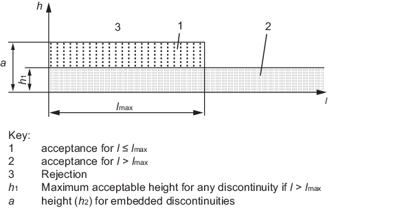
Figure 13.2.5 General scheme for acceptance
conditions
Table 13.2.9 Applicable methods for testing
of materials and weld joints
| Materials and weld joints
|
Parent material thickness
|
Applicable volumetric NDE test methods (see Notes 1 &
2)
|
| Ferritic and austenitic stainless steel butt welds with full
penetration
|
thickness < 6 mm
|
RT,
RT-D
|
| 6
mm ≤ thickness < 8 mm
|
RT,
RT-D, PAUT, TOFD
|
| thickness ≥ 8 mm
|
RT,
RT-D, UT, PAUT, TOFD
|
| Ferritic and austenitic stainless steel tee joints and
corner joints with full penetration
|
6 mm
≤ thickness < 8 mm
|
RT,
RT-D, PAUT (see Note 3)
|
| thickness ≥ 8 mm
|
RT, RT-D, UT, PAUT (see Note 3)
|
| Ferritic cruciform joints with full penetration
|
6 mm
≤ thickness < 8 mm
|
RT,
RT-D, PAUT (see Note 3)
|
| thickness ≥ 8 mm
|
RT, RT-D, UT, PAUT (see Note 3)
|
| Ferritic tee joints, corner joints and cruciform joints without full
penetration and fillet welds
|
All
|
UT,
PAUT, RT (see Notes 3 & 4)
|
|
Note 2. TOFD is
only applicable to ferritic welds.
Note 3. RT and
RT-D may be applied; however, it is noted that for these
configurations, there may be limitations.
Note 4. UT and
PAUT may be used to check the extent of penetration in tee, corner and
cruciform joints.
|
2.12.7 Checkpoints
examined at the pre-assembly stage are to include ultrasonic testing
on examples of the stop/start points of automatic welding and magnetic
particle inspection of weld ends.
2.12.8 Checkpoints
examined at the assembly stage are generally to be selected from those
welds intended to be examined as part of the agreed quality control
programme to be applied by the builder. The locations and number of
checkpoints are to be approved by the Surveyor.
2.12.9 Where
components of the structure are subcontracted for fabrication, the
same inspection regime is to be applied as if the item had been constructed
within the main contractor’s works. In these cases, particular
attention is to be given to highly loaded fabrications (such as stabiliser
fin boxes) forming an integral part of the hull envelope.
2.12.10 Particular
attention is to be paid to highly stressed items. Magnetic particle
inspection is to be used at ends of fillet welds, T-joints, joints
or crossings in main structural members and at stern frame connections.
2.12.11 Special
attention is to be given to the examination of plating in way of lifting
eye plate positions to ensure freedom from cracks. This examination
is not restricted to the positions where eye plates have been removed,
but includes the positions where lifting eye plates are permanent
fixtures.
2.12.12 Checkpoints
for volumetric examination are to be selected so that a representative
sample of welding is examined.
2.12.13 Typical
locations for volumetric examination and number of checkpoints to
be taken are given in the relevant Sections of the Rules. A list of
the proposed items to be examined is to be submitted for approval.
2.12.15 For
all ship types, the builder is to carry out random non-destructive
examination at the request of the Surveyor.
2.12.16 Results
of non-destructive examinations made during construction are to be
recorded and evaluated by the builder on a continual basis in order
that the quality of welding can be monitored. These records are to
be available to the Surveyor.
2.12.17 The
extent of applied non-destructive examinations is to be increased
when warranted by the analysis of previous results.
2.13 Weld repairs
2.13.1 The full
extent of any weld defect is to be ascertained by applying additional
non-destructive examination where required. Unacceptable defects are
to be completely removed and, where necessary, re-welded and re-examined
in accordance with the requirements of Ch 13, 1.15 Rectification of welds defects.
2.13.2 During
the assembly of large components, root gaps in excess of those specified
in the approved welding procedure may be rectified by welding.
2.13.3 Rectification
of wide root gaps in butt welds, up to a maximum gap of 16 mm, may
be performed provided that the length of these areas is small in relation
to the whole weld length. Repairs may be executed by applying weld
buttering layers to one edge of the weld joint, followed by machining
or grinding to return the root opening to the required dimensions.
The weld buttering and filling of the joint are to be in accordance
with welding procedures qualified in accordance with Ch 12 Welding Qualifications.
2.13.4 For sub-assemblies,
rectification of wide root gaps may be performed using a backing strip,
provided that it is removed on completion of the welding.
2.13.5 Rectification
of wide root gaps in fillet welds may be carried out as follows:
-
where the root gap, g, is in excess of 3 mm, but not greater than 5 mm, the fillet
leg length, z, may be increased by g –
2,0 mm;
-
where the root gap
is in excess of 5 mm, the joint detail may be changed into a full
penetration weld.
2.13.6 Where
repair welds are made using small weld beads, suitable precautions
(including preheat) are to be taken to avoid high hardness and possible
cold cracking.
2.14 Welding afloat with water backing
2.14.1 Welding
afloat with water backing is not recommended due to the additional
precautions required during survey and therefore, is generally not
permitted. However consideration may be given to welding afloat with
water backing after specific LR approval has been obtained by the
yard or fabricator prior to such welding being carried out. Such approval
will only be given once all of the following conditions are satisfied:
-
The welding procedure
qualification tests are carried out on steel plates with water backing
and the water is maintained at the flow rate and minimum water temperature
anticipated during fabrication.
-
The carbon equivalent
of the steel plates used in the welding procedure qualification tests
are to be greater than 0,41 per cent based on the IIW formula. Where
it can be shown that all hull steel plates and new sections will have
a carbon equivalent value below this figure, steel plates with the
maximum carbon equivalent value may be used for the welding procedure
qualification tests.
-
Welding procedure
qualification tests are carried out without preheat.
-
The thickness of
steel plate used in the welding procedure qualification test is the
minimum hull plate thickness to be used during fabrication.
-
The maximum measured
hardness on the completed welding procedure qualification assembly
is less than or equal to 350 HV10. Following fabrication welding,
10 per cent of welds are to be hardness tested in way of heataffected
zones at weld starts to confirm compliance with the 350 HV10 limit.
-
The heat input used
in the welding qualification test is the minimum permitted heat input
during fabrication.
-
Only low hydrogen
welding consumables (H5) are used.
-
In addition to normal
non-destructive testing for welds, 10 per cent of the welds are additionally
subject to magnetic particle inspection 48 hours after welding is
complete.
-
The welding procedure
qualification tests for the repair of welds carried out afloat with
water backing are to be carried out on test pieces that have previously
been welded afloat and also meet the requirements above.
2.14.2 For new
construction, conversion or permanent repairs, wet underwater welding
is not permitted.
|