
Section
2 Welding procedure qualification tests for steels
2.1 General
2.1.1 The requirements
of this Section relate to welding procedure test requirements of carbon,
carbon-manganese steels and low alloys steels. Additional requirements
for austenitic and austenitic/ferritic duplex stainless steels, aluminium
and copper alloys are specified in Sections 3 and 4 respectively.
2.1.2 Prior to
performing the welding procedure qualification test, the manufacturer
is to present to the Surveyor a preliminary Welding Procedure Specification
(pWPS) detailing the welding processes, positions, joint types, materials
and heat treatments to be performed during the test. The pWPS is to
be presented for information prior to commencing the test.
2.1.3 The type
and extent of testing to be applied to each welding procedure test
is to be in accordance with subsequent Sections of this Chapter.
2.1.4 For the
welding procedure approval, the welding procedure qualification tests
given in this Section are to be carried out with satisfactory results.
Welding procedure specifications are to refer to the test results
achieved during welding procedure qualification testing.
2.2 Welding variables
2.2.1 In order
that the conditions of the qualification test may be applied to production
welding operations, the appropriate variables are to be recorded by
the manufacturer during welding and testing from the following list:
-
The unique qualification
reference number and the date of welding;
-
The material type,
grade, product form, dimensions and identification;
-
Welding process(es),
including tack welds;
-
Joint type, dimensions
and surface condition;
-
Welding position(s);
-
Welding technique(s),
weaving, multiple electrodes, etc;
-
Welding consumables
including fluxes, shielding gases, etc;
-
Control of consumables,
baking or drying conditions, etc;
-
Welding parameters,
current, voltages, travel speeds, etc;
-
Number and sequence
of weld runs;
-
Backing materials
including any backing gas;
-
Preheats and interpass
temperatures;
-
Methods used for cleaning
and inspection of root deposits;
-
Post-weld heat treatment,
temperature and cycle times;
-
Special weld profiling
requirements.
2.2.2 Other variables
may need to be recorded depending on the particular welding process
or application and are to be agreed with the Surveyor, for example
the peak and base current and cycle times for pulse welding, electrode
type and nozzle size for GTAW welding, etc.
2.3 Steel test assemblies
2.3.1 Tests are to be performed using the welding process and positions
anticipated for actual construction. The weld test assemblies are to be representative
of construction conditions and are to be welded in the same manner as intended for the
actual production welds. Where prefabrication primers are used in the shipyard, these
are to be included in the test assemblies.
2.3.2 For plate
tests, the direction of plate rolling relative to the weld direction
is to be considered. Where the material used for the test requires
longitudinal impact tests, the plate rolling direction is to be perpendicular
to the weld direction and for material which requires impact testing
in the transverse direction, the rolling direction is to be parallel
to the weld direction. For weld tests intended for liquefied gas storage
or cargo tanks and associated process pressure vessels, the direction
of plate rolling is to be parallel to the weld direction in all cases.
2.3.4 Welding
procedure test assemblies are to be welded separately from production
welds and are to be marked with the unique test identification number.
The individual pieces of the test assembly may be held together to
maintain their relative joint conditions by means of suitable tack
welds, clamps or strongbacks.
2.3.5 Welding
of the test assemblies and testing of test specimens is to be monitored
by the Surveyor.
2.3.7 Designations
for equivalent welding positions shown by different standards are
shown in Table 12.2.1 Equivalent designations of welding
positions.
Table 12.2.1 Equivalent designations of welding
positions
| Weld position
|
Standard
|
| ISO
6947
|
AWS
|
|
Plate butt welds
|
|
|
|
| Flat
|
D
|
PA
|
1G
|
| Horizontal
|
X
|
PC
|
2G
|
| Vertical, weld up
|
Vu
|
PF
|
3G
|
| Vertical,
weld down
|
Vd
|
PG
|
3G
|
| Overhead
|
O
|
PE
|
4G
|
|
Pipe butt welds
|
|
|
|
| Pipe
horizontal, rotated, weld horizontal
|
D
|
PA
|
1G
|
| Pipe
vertical, not rotated, weld horizontal
|
X
|
PC
|
2G
|
| Pipe
horizontal, not rotated, weld flat, vertical and overhead
|
D+Vu+O
|
PH
|
5G
|
|
|
D+Vd+O
|
PJ
|
|
| Pipe
inclination fixed, not rotated
|
45o
|
H-L045
|
6G
|
|
|
|
J-L045
|
|
|
Plate fillet welds
|
|
|
|
| Flat
|
D
|
PA
|
1F
|
| Horizontal
|
X
|
PB
|
2F
|
| Vertical
up
|
Vu
|
PF
|
3F
|
| Vertical
down
|
Vd
|
PG
|
3F
|
| Overhead
|
O
|
PD
|
4F
|
|
Pipe fillet welds
|
|
|
|
| Flat,
pipe rotated
|
D
|
PA
|
1FR
|
| Horizontal, pipe fixed
|
X
|
PB
|
2F
|
| Horizontal, pipe rotated
|
D
|
PB
|
2FR
|
| Overhead,
pipe fixed
|
O
|
PD
|
4F
|
| Multiple, pipe fixed
|
D+Vu+O
|
PF
|
5F
|
| D+Vd+O
|
PG
|
|
2.4 Welding of steel test assemblies
2.4.1 Welding
of the test assembly is to be carried out in accordance with the agreed
pWPS. Where, during the progress of the test, it is found necessary
to change the conditions specified on the pWPS, this is to be brought
to the attention of the Surveyor. If agreed, the test may be permitted
to continue with the new conditions and these are to be recorded.
2.4.2 Where the
production work requires welding over tack welds, the test is to simulate
this condition and the tack welds are to be included in the inspection
length of the test weld and their position recorded.
2.4.3 For manual
and semi-automatic welding processes, weld stops and re-starts are
to be included in the inspection length of the test weld.
2.4.4 Fillet weld
test assemblies are welded on one side only.
2.4.5 Where the
construction welding is predominately fillet welding, in addition
to the butt weld qualification test, a fillet weld qualification test
is to be performed to confirm that acceptable weld quality is achieved.
2.5 Non-destructive examination (NDE)
2.5.1 On completion
of welding, prior to sectioning for mechanical tests, the inspection
length of the test assembly is to be subjected to both visual examination
and surface crack detection.
2.5.2 Butt weld
assemblies are also to be subjected to radiographic or ultrasonic
examination over the whole inspection length of the weld.
2.5.3 For welds in steels with specified yield strength less than 420
N/mm2, and with carbon equivalent less than or equal to 0,41 per cent, NDE
may be performed as soon as the test assembly has cooled to ambient temperature. For
other steels, NDE is to be delayed for a period of at least 48 hours after the test
assembly has cooled to ambient temperature.
2.5.4 Where post-weld
heat treatment is required, NDE is to be performed after the heat
treatment is complete.
2.5.5 All NDEs
are to be carried out in accordance with the requirements of Ch 1, 5 Non-destructive examination. Assessment of results is to be in
accordance with ISO 5817 Level B except for excess convexity and excess
throat thickness where Level C will apply. Linear porosity is not
permitted.
2.5.7 Where the
test assembly does not satisfy the nondestructive examination acceptance
criteria, the test is to be rejected. A duplicate test assembly may
be welded using the original welding conditions. If this fails NDE,
the welding procedure is to be considered as incapable of achieving
the requirements without modification.
2.5.8 Subject
to prior agreement with the Surveyor, where unacceptable imperfections
are of a volumetric nature and are localised in one small area of
the test assembly, the test may be permitted to continue and specimens
for destructive testing may be removed, avoiding this area.
2.6 Destructive tests – General requirements
2.6.1 The weld
test assembly may only be sectioned for destructive testing after
any heat treatment and the required non-destructive examinations have
been completed successfully.
2.6.4 Where a
weld test is made between materials of different grades, the acceptance
criteria that are to be applied are those applicable to the lower
grade material.
2.7 Destructive tests for steel butt welds
2.7.1 The test assembly is to be sectioned for mechanical testing in accordance
with Figure 12.2.8 Butt welds in plate or Figure 12.2.9 Butt welds in pipe less than 750
mm diameter.
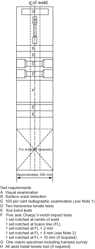
Note 1 Radiographic examination may be
replaced by ultrasonic examination for test assembly thickness of 8 mm or
above.
Figure 12.2.8 Butt welds in plate
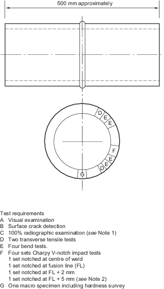
Note 1 Radiographic examination may be replaced by ultrasonic examination for test
assembly thickness of 8 mm or above.
Figure 12.2.9 Butt welds in pipe less than 750
mm diameter
2.7.2 The longitudinal
all weld metal tensile test specimen is to be of circular cross-section
as detailed in Ch 11, 2.1 Dimensions of test specimens 2.1.1. Where
more than one welding process or type of consumable has been used
to make the weld, test specimens are to be removed from each respective
area of the weld. This does not apply to the process or consumables
used to make the root or first weld run. During the test, the yield
or proof stress, ultimate tensile strength, and elongation to failure
are to be recorded.
2.7.3 Where approved
welding consumables have been used, the longitudinal all weld metal
tensile test may be omitted. For Type C independent tanks intended
for liquefied gases, the all weld tensile test is mandatory for all
welding procedure tests.
2.7.5 Where the
maximum load required to fracture the transverse tensile specimen
is likely to exceed the capacity of the tensile testing equipment,
several tensile specimens may be removed through the thickness and
tested. Specimens are to be prepared such that they overlap in the
thickness direction so that the full plate thickness is tested.
2.7.6 Transverse
bend specimens of rectangular section are to be prepared with the
weld centred in the middle of the specimen as shown in Figure 12.2.10 Transverse bend test specimens. For material of thickness
12 mm or greater, the face and root bends may be substituted by side
bend tests. Where there is a significant difference between the strength
of the weld and base material, longitudinal bend specimens may be
used. The weld reinforcement may be removed by grinding or machining
prior to testing and the edges rounded to a radius not exceeding 10
per cent of the specimen thickness. Each specimen is to be bent through
an angle of at least 180°. The bend test ratio is to be the lesser
of the following:
-
or
-
|
D
f
|
= |
100/E
m (rounded up to the next whole number) |
2.7.9 For offshore
structures and pressure vessels, impact test specimens are not required
to be notched at the FL + 10 mm location. Where more than one welding
process or type of consumable has been used to make the weld, test
specimens are to be removed from the respective areas of the weld.
This does not apply to the process or consumables used solely to make
the root or first weld run.
2.7.11 At least
one macro examination specimen is to be removed from the test plate,
near the end where welding started. The specimen is to include the
complete cross-section of the weld and the heat affected zone and
be prepared and etched to clearly reveal the weld runs and the heat
affected zone. Examination is to be performed under a magnification
of between x5 and x10.
2.7.12 A chemical
analysis of the weld metal is to be performed on the macro specimen
where approved welding consumables have not been used. The results
are to comply with the limits given in the welding consumable specification.
2.7.13 Hardness surveys:
- A Vickers hardness survey is to be performed on the macro
specimen taken from the weld start end of the test assembly in accordance with that
shown in Figure 12.2.14 Hardness testing locations for butt welds, using a test load not in excess of 10 kg. For each
row of indents, there are to be a minimum of 3 individual indentations in the weld
metal, the heat affected zones (both sides), the base metal (both sides), and in
addition, 2 indentations are required in the grain coarsened heat affected zone, one
above and one below the hardness survey row. The recommended distance between indents
is 1,0 mm, but the distance between indents should not be less than the minimum
specified in ISO 6507-1.
- For steel grades EH47, EH47-BCA1 and EH47-BCA2 an additional row
of indents is required from the mid-thickness of macro specimen.
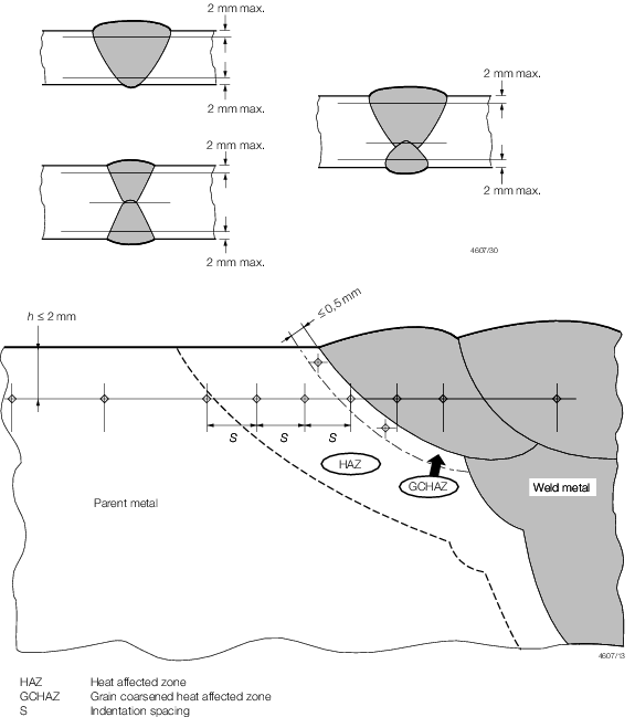
Figure 12.2.14 Hardness testing locations for butt welds
2.8 Destructive tests for steel fillet welds
2.8.2 Two fracture
test specimens are to be removed from the test weld and are to be
subjected to testing by bending the upright plate onto the through
plate to produce fracture, as shown in Figure 12.2.3 Fillet weld test assembly in plate.
2.8.3 At least
three macro examination specimens are to be removed from the test
plate. The specimens are to include the complete cross-section of
the weld and the heat affected zone and is to be prepared to clearly
reveal the weld runs and the heat affected zone. One of the specimens
is to include a weld stop/start position. Examination is to be performed
under a magnification of between x5 and x10.
2.8.4 A Vickers
hardness survey is to be performed on the macro specimen taken from
the weld start end of the test assembly in accordance with that shown
in Figure 12.2.15 Hardness test locations for fillet welds, using a test
load not exceeding 10 kg.
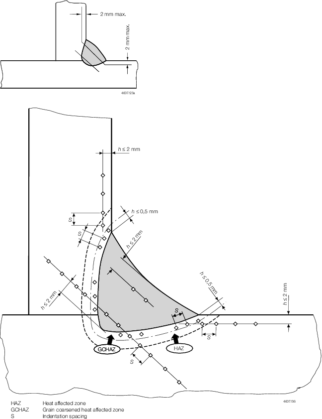
Figure 12.2.15 Hardness test locations for fillet welds
2.9 Destructive tests for T, K, Y steel nozzle welds
2.10 Destructive tests for steel pipe branch welds
2.10.1 Pipe branch
welds may be by either full penetration, partial penetration or fillet
welded, depending on the application and the approved plans. Where
these types of welded joints are used, tests are to be performed which
simulate the construction conditions.
2.10.2 The test
weld assembly is to simulate the smallest angle between the branch
and main pipe and is to be subjected to macro-examination and hardness
testing, as follows:
-
For a branch weld
that is full penetration, testing is to be performed in accordance
with the requirements for ‘T', ‘K’ and ‘Y’
joints in Ch 12, 2.9 Destructive tests for T, K, Y steel nozzle welds.
-
For a branch weld
that is either a partial penetration or fillet weld, testing is to
be in accordance with the requirements for fillet welds in Ch 12, 2.8 Destructive tests for steel fillet welds.
2.11 Destructive tests for weld cladding of steel
2.11.2 Where
the weld cladding is not considered as contributing to the strength
of the component, but is required for corrosion or wear resistance,
the type and location of test specimens are to be in accordance with Figure 12.2.18 Type and location of test specimens for weld cladding, except that tensile and
impact tests are not required.
2.11.3 Where
the weld cladding is applied for corrosion resistance, in addition
to the above, weld metal analysis is to be performed on one of the
micro-sections, on the final weld surface but 2 mm deep. The analysis
is to be within the limits specified for the corrosion resistance
required.
2.12 Mechanical test acceptance criteria for steels
2.12.1
Longitudinal
all weld metal tensile test:
-
In general, the longitudinal all weld tensile test is to meet the
minimum properties specified in Table 11.3.2 Requirements for deposited metal
tests (covered electrodes) or Table 11.4.2 Requirements for deposited metal
tests (wire-flux combinations), as appropriate to the grade of steel and
welding process used in the test.
-
Where the application
is such that no consumable approvals are specified in Ch 11 Approval of Welding Consumables, the longitudinal all weld tensile
test tensile is to meet the minimum properties specified for the base
materials used in the test.
-
For pressure vessels
manufactured from carbon or carbon/manganese steels, the tensile strength
from the longitudinal all weld tensile test is not to be less than
the minimum specified for the plate material and is not to be more
than 145 N/mm2 above this value,see
Ch 13, 4.8 Mechanical requirements 4.8.3.
-
For tanks intended
for liquefied gases, the weld metal strength may be lower than the
minimum specified for the base metal provided that the application
has design approval. In such cases the strength is not to be less
than that specified in the approved design.
-
For base metal grades with minimum specified yield strength level of 890 and 960
N/mm2, the weld metal strength may be lower than the minimum
specified for the base metal provided that the application has design approval for
the undermatching weld metal. In such cases the weld metal strength is not to be
less than that specified in the approved design.
2.12.3
Bend
tests:
-
In general, bend
tests are to exhibit no defects exceeding 3,0 mm measured in any direction
across the tension face of the specimen after being bent over the
required diameter of former to the appropriate angle.
-
Bend tests for pressure
vessel applications are to exhibit no defects exceeding 3,0 mm measured
along the specimen or 1,5 mm measured transverse to the specimen axis,
after bending.
-
In all cases, premature
failure of the bend tests at the edges of the specimen is to not be
cause for rejection unless these are associated with a weld defect.
2.12.4
Impact
toughness tests:
-
Impact test specimens
for hull construction are to be tested at the temperature, and are
to achieve the minimum impact energy, as specified in Table 12.2.2 Impact test requirements for butt
joints (t ≤ 50 mm) see Notes 1 and 2 and Table 12.2.3 Impact test requirements for butt
joints (t > 50 mm) see Notes 1 and 2 .
-
Impact test specimens
for applications other than hull construction are to be tested at
the same temperature and achieve the same minimum energy values, as
specified for the base materials used in the test.
-
Impact test acceptance
criteria are to be in accordance with the above unless the Rules applicable
to the particular construction specify more stringent requirements.
-
For quench and tempered steels, the required test temperature and
absorbed energy are to be in accordance with that specified for the parent
materials. For base metal grades with minimum specified yield strength level of
890 and 960 N/mm2, the weld metal absorbed energy may be lower than the
minimum specified for the base metal provided that the application has design
approval for the undermatching weld metal. In such cases the absorbed energy is
not to be less than that specified in the approved design.
Table 12.2.2 Impact test requirements for butt
joints (t ≤ 50 mm) see Notes 1 and 2
| Grade of steel
|
Test temperature (°C)
see Note 4
|
Average energy (J) minimum, see Note 4
|
| Manual or
semi-automatic welded joints
|
Automatically welded joints
|
| Downhand, Horizontal, Overhead
|
Vertical upward, Vertical
downward
|
| A,
see Note 3
|
20
|
47
|
34
|
34
|
| B,
see Note 3, D
|
0
|
| E
|
-20
|
| AH32,
AH36
|
20
|
| DH32,
DH36
|
0
|
| EH32,
EH36
|
-20
|
| FH32,
FH36
|
-40
|
| AH40
|
20
|
39
|
39
|
| DH40
|
0
|
| EH40
|
-20
|
| FH40
|
-40
|
Note
2. These requirements are to apply to
test piece of which butt weld is perpendicular to the rolling
direction of the plates.
Note
3. For grade A and B steels average
absorbed energy on fusion line and in heat affected zone is to be a
minimum of 27 J.
Note
4. For Naval ships both the test
temperature and value of minimum energy absorbed are to be those
specified for the parent material.
|
Table 12.2.3 Impact test requirements for butt
joints (t > 50 mm) see Notes 1 and 2
| Grade of steel
|
Test temperature (ºC)
See Note 2
|
Average energy (J) minimum, see Note 2
|
| Manual or semi-automatic welded joints
|
Automatically welded
joints
|
Downhand, Horizontal,
Overhead
|
Vertical upward,
Vertical downward
|
| A
|
20
|
34
|
34
|
34
|
| B
|
0
|
34
|
34
|
34
|
| D
|
0
|
47
|
38
|
38
|
| E
|
–20
|
47
|
38
|
38
|
| AH32, AH36
|
20
|
47
|
41
|
41
|
| DH32, DH36
|
0
|
47
|
41
|
41
|
| EH32, EH36, EH36-BCA1
|
–20
|
47
|
41
|
41
|
| FH32, FH36
|
–40
|
47
|
41
|
41
|
| AH40
|
20
|
50
|
46
|
46
|
| DH40
|
0
|
50
|
46
|
46
|
| EH40, EH40-BCA1, EH40-BCA2
|
–20
|
50
|
46
|
46
|
| FH40
|
–40
|
50
|
46
|
46
|
| EH47, EH47-BCA1, EH47-BCA2
|
–20
|
64
|
64
|
64
|
Note
1. These requirements are to apply to
test piece of which butt weld is perpendicular to the rolling
direction of the plates.
Note
2. For the Naval ships, both the test
temperature and value of minimum absorbed energy are to be those
specified for the parent material.
|
2.12.5
Macro-examination:The macro-section is to reveal an even weld profile blending
smoothly with the base material. The weld dimensions are to be in
accordance with the requirements of the pWPS and any defects present
are to be assessed against the non-destructive examination acceptance
criteria given in Ch 12, 2.5 Non-destructive examination (NDE) 2.5.5.
2.12.6 Hardness surveys:
- The maximum hardness value is not to exceed 350 Hv for steel
grade EH47 and 380 Hv for steel grades EH47-BCA1 and EH47-BCA2.
- For all other steel grades, themaximum hardness value is not to
exceed 350 Hv for steels with a specified minimum yield strength up to ≤420
N/mm2, nor exceed 420 Hv for steels with a specified minimum yield
strength in the range 420 N/mm2 t o690 N/mm2.
2.12.7
Weld
fracture or break tests (for pressure vessel test welds): The
faces of the broken fillet weld fracture or weld break test are to
be examined for defects and assessed in accordance with the non-destructive
acceptance criteria given in ISO 5817 Level B, except for excess convexity
and excess throat thickness where Level C will apply.
2.13 Failure to meet requirements (Retests)
2.13.1 Where
a tensile, bend or hardness specimen fails to meet requirements, further
test specimens may be removed and tested in accordance with the requirements
of Ch 2, 1.4 Re-testing procedures 1.4.1.
2.13.2 Where
an impact specimen fails to meet requirements, a further set of three
specimens may be removed and tested in accordance with the requirements
of Ch 2, 1.4 Re-testing procedures 1.4.4.
2.13.3 Where
a macro specimen reveals a defect that is planar in nature, the welding
procedure test is to be considered as not satisfying the requirements
and a new test assembly is required.
2.13.4 Where
a macro specimen does not meet requirements as a result of a volumetric
imperfection exceeding the permitted size, two additional specimens
may be removed from the same test weld and examined. If either of
these macro-sections also fails to satisfy the requirements, the welding
procedure is to be considered as not having met the requirements.
2.13.5 If there
is a single hardness value above the maximum values specified, additional
hardness tests are to be carried out, either on the reverse of the
specimen, or after sufficient grinding of the tested surface. None
of the additional hardness values is to exceed the maximum hardness
values specified, otherwise the welding procedure is to be considered
as not having met the requirements.
2.13.6 Where
there is insufficient material available in the welded test assembly
to provide re-test specimens, subject to prior agreement with the
Surveyor, a second assembly may be welded using the same conditions
as the original test weld.
2.14 Test records
2.14.1 The procedure
qualification record (PQR) is to be prepared by the manufacturer and
is to include details of the welding conditions used in the test specified
in Ch 12, 2.2 Welding variables and the results of all the
non-destructive examinations and destructive tests, including re-tests.
2.14.2 Provided
that the PQR lists all the relevant variables and there are no inconsistent
features and the results satisfy the requirements, the PQR may be
endorsed by the Surveyor as satisfying the requirement of the Rules, see also
Ch 12, 1.1 General 1.1.4.
2.15 Range of approval
2.15.1 A welding
procedure qualification test that has successfully met the requirements
may be used for a wider range of applications than those used during
the test.
2.15.2 Changes
outside of the ranges specified are to require a new welding procedure
test.
2.15.3 Other
ranges of approval from those specified in this Section may be agreed
with the Surveyor, provided that they are in accordance with recognised
National or International Standards.
2.15.4
Manufacturer. A welding procedure qualified by a manufacturer is valid for
welding in workshops under the same technical and quality management.
2.15.5
Welding
process and technique. The welding process and welding techniques
approved are to be those employed during the welding procedure qualification
test. Where multiple welding processes are used, these are to be employed
in the same order as that used in the welding procedure qualification
test. However, it may be acceptable to delete or add a welding process
where it has been used solely to make the first weld run in the root
of the joint, provided back gouging or grinding of the root weld is
specified on the WPS. For multi-process procedures, the welding procedure
approval may be carried out with separate welding procedure tests
for each welding process.
2.15.6
Welding
positions. Approval for a test made in any position is restricted
to that position. To qualify a range of positions, test assemblies
are to be welded for the highest heat input position, and the lowest
heat input position, and all applicable tests are to be made on those
assemblies. The above excludes welding in the vertical position with
travel in the downward direction which will always require separate
qualification testing and only be acceptable for that position.
2.15.7
Joint
types. A qualification test performed on a butt weld may be
considered acceptable for fillet and partial penetration welds, provided
the same welding conditions are used. The range of approval depending
on the type of joint for butt welds is given in Table 12.2.4 Range of approval for different
types of butt joints.
Table 12.2.4 Range of approval for different
types of butt joints
| Type of welded joint for test assembly
|
Range of
approval
|
| Butt
welding
|
One side
|
With
backing
|
A
|
A,C
|
| Without backing
|
B
|
A,B,C,D
|
|
|
|
|
|
| Both sides
|
With
gouging
|
C
|
C
|
| Without
gouging
|
D
|
C,D
|
2.15.8
Range
of material types:
-
For normal and higher strength steels, for each strength level,
welding procedures are considered applicable to the same and lower toughness
grades as that tested. For each toughness grade, welding procedures are considered
applicable to the same and two lower strength levels as that tested with the
exception of the two-run (T) or high welding heat input (A) techniques where
acceptance is limited to the strength level used in the test.
-
A qualification test performed on H47 strength grade steels may be
used to weld the steel of the same strength level or grade H40 and all lower
toughness grades to that tested.
-
The range of approval for the crack arrest steel grades is shown in
Table 12.2.5 Range of approval for crack arrest steel grades. Welding procedures qualified on non-brittle crack
steel grades are also considered applicable to corresponding brittle crack arrest
steel grades where production heat input does not exceed 50 KJ/cm. For higher heat
input, the welding procedures are to be qualified on crack arrest steel grades.
Guidance: As an example, the corresponding crack arrest steel grades
for non-brittle crack arrest steel grade EH40 are EH40-BCA1 and EH40-BCA2.
-
For high strength quenched and tempered steels, for each strength
level, welding procedures are considered applicable to the same and lower
toughness grades as that tested. For each toughness grade, welding procedures are
considered applicable to the same and one lower strength level as that tested. The
approval of quenched and tempered steels does not qualify thermo-mechanically
rolled steels (TMCP steels) and vice versa.
-
For weldable C and C-Mn steel forgings, welding procedures are
applicable to the same and lower strength level as that tested. The approval of
quenched and tempered steel forgings does not qualify other delivery conditions
and vice versa.
-
For weldable C and C-Mn steel castings, welding procedures are
applicable to the same and lower strength level as that tested. The approval of
quenched and tempered steel castings does not qualify other delivery conditions
and vice versa.
- Dissimilar materials. Where a qualification test has been performed
using dissimilar materials, acceptance is to be limited to the materials used in the
test.
2.15.9
Thickness
and diameter range:
-
For straight butt
welds, the material thickness range to be approved is to be based
on the thickness of the test piece and the type of weld as shown in Table 12.2.6 Welding procedure thickness
approval range - Butt welds.
-
For butt welds between
plates of unequal thickness, the lesser thickness is the ruling dimension.
-
For fillet welds
and ‘T’ butt welds, Table 12.2.6 Welding procedure thickness
approval range - Butt welds is to be applicable to both the abutting and through
member thicknesses. In addition to the requirements of Table 12.2.6 Welding procedure thickness
approval range - Butt welds, the range of approval
of throat thickness ‘a’ for fillet welds
is to be as follows:
- single run: 0,75a to 1,5a
- multi-run: as for butt welds with multi-run (i.e. a =t)
-
Notwithstanding any
of the above, the approval of maximum thickness of base metal for
any technique is to be restricted to the thickness of the test assembly
if three of the hardness values in the heat affected zone are found
to be within 25 Hv of the maximum permitted.
-
The material diameter
range to be approved is to be based on the diameter of the test piece
and type of weld as shown in Table 12.2.7 Diameter range approved.
Table 12.2.5 Range of approval for crack arrest steel grades
| Material grade for
the test assembly
|
Range of
Approval
|
| EH36-BCA1
|
EH36-BCA1
|
| EH40-BCA1
|
EH40-BCA1
|
| EH40-BCA2
|
EH40-BCA2,
EH40-BCA1
|
| EH47-BCA1
|
EH47-BCA1
|
| EH47-BCA2
|
EH47-BCA2,
EH47-BCA1
|
Table 12.2.6 Welding procedure thickness
approval range - Butt welds
Test thickness,
see Note
1
(t in mm)
|
Range approved
|
All
multi-run butt welds and all fillet welds
see Notes 2
and 3
|
All single-run or two-run (T
technique) butt welds
|
| t ≤ 3
|
t to 2t
|
|
| 3 < t ≤ 12
|
3 to 2t
|
0,7t to
1,1t
|
| 12 < t ≤ 100
|
0,5t to
2t,
see Note 1
|
0,7t to
1,1t
see Note 4
|
|
t > 100
|
0,5t to
1,5t
|
0,7t to
1,1t
see Note 4
|
|
|
Note
1. Subject to a maximum limit of 150
mm.
|
Note
2. For multi process procedures, the
recorded thickness contribution of each process is to be used as a
basis for the range of approval of the individual welding process.
|
Note
3. For vertical down welding, the test
piece thickness, t, is the upper limit of the range of
application.
|
Note
4. For processes with heat input over 5,0
kJ/mm, the upper limit of the range of approval is to be 1,0 t.
|
Table 12.2.7 Diameter range approved
- Diameter used for test,
- see Note 1
|
Range of
diameters
approved
|
|
|
- 0,5D to 2D
- > 0,5D, see Note 2
|
Note
1.
D is the outside diameter of the pipe or the smallest side
dimension of rectangular hollow section.
Note
2. Lower diameter range limited to 25 mm
minimum.
Note 3. Qualification given for plates also
covers pipes when the outside diameter is greater than 500 mm or when the
diameter is greater than150 mm welded in the Downhand (D) or Horizontal (
X ) positions.
|
2.15.10
Welding
consumables:
-
For manual and semi-automatic
welding used for the fill and capping weld runs, it may be acceptable
to change the brand or trade name of the welding electrode or wire
from that used in the test, provided the proposed alternative has
the same or higher approval grading and the same flux type (e.g. basic
low hydrogen, rutile, etc.) as used in that test.
-
For the consumable
used to make the root weld of full penetration butt welds made from
one side only, no change in the type or trade name of the consumable
or backing material is permitted. Alternative backing materials may
be used provided they are equivalent to those used for approval. Where
the approved backing material is a low hydrogen grade and the steel
being welded requires a low hydrogen backing material, testing of
the alternative backing material is to confirm compliance with the
requirements of Ch 11, 7 Consumables for use in one-side welding with temporary backing materials.
-
For processes with
heat input over 5 kJ/mm, no change in the type or trade name of the
consumable is permitted.
2.15.11
Shielding
gas. For gas shielded welding processes, a change in shielding
gas composition from that used in the test will require a new qualification
test.
2.15.12
Heat
Input. The upper limit of heat input approved is 25 per cent
greater than that used in the test, or 5,5 kJ/mm, whichever is the
smaller. With heat input over 5,0 KJ/mm, the upper limit is 10 per
cent above that used in the test. In all cases, the lower limit of
heat input approved is 25 per cent lower than that used in the test.
2.15.13
Current
type. The current type used during the qualification test is
to be the only type approved. Additionally, changes from or to pulsed
current require new qualification tests.
2.15.14
Preheat
temperature. The temperature used during the test is to be
the minimum approved. Higher temperatures may be specified for production
welds up to the maximum interpass temperature. Where hardness tests
have been performed that exhibit results near the maximum permitted,
an increase in preheat temperature is required when welding material
of greater thickness than that used in the test.
2.15.15
Interpass
temperature. The maximum interpass temperature recorded during
qualification testing is to be the maximum approved. Lower temperatures
may be specified for production welding, but no lower than the minimum
preheat temperature.
2.15.16
Post-weld
heat treatment. A qualification test performed with no post
weld heat treatment is only acceptable for production welding where
no heat treatment is applied. Where the qualification test has included
a post weld heat treatment, this is to be applied to all welds made
with the welding procedure. The average specified soak temperature
may vary by up to 25°C from that tested.
2.15.17
Shop
primers. Welding procedure qualification with shop primers
qualifies welds without primer, but not vice versa.
2.16 Welding procedure specification (WPS)
2.16.1 A welding
procedure specification (WPS) is to be prepared by the manufacturer
detailing the welding conditions and techniques to be employed for
production welding. The WPS is to be based on the conditions and variables
used during the qualification test, and is to include all the ranges
of the essential variables specified in Ch 12, 2.2 Welding variables 2.2.1 and Ch 12, 2.15 Range of approval.
2.16.2 The WPS
should reference the procedure qualification record upon which it
is based and is to be approved by the Surveyor prior to commencing
production welding.
|