
Section
5 Design loading
5.1 General
5.1.1 This
Section contains the design heads/pressures to be used in the derivation
of scantlings for decks, tank tops and transverse bulkheads. These
are given in Table 3.5.1 Design heads and permissible cargo
loadings.
Table 3.5.1 Design heads and permissible cargo
loadings
| Structural
item and position
|
Component
|
Standard
stowage rate C, in m3/tonne
|
Design
loading p, in kN/m2
|
Equivalent design head h
i in metres
|
Permissible cargo loading in kN/m2
|
Equivalent
permissible head, in metres
|
| Design heads and permissible cargo loadings (SI
units)
|
| Weather deck (general cargo)
|
|
|
|
h
1
|
|
|
| (a) Loading for minimum scantlings
|
|
|
|
|
|
|
| Forward of 0,075L from F.P.
|
Beams and longitudinals
|
1,39
|
12,73
|
1,8
|
8,5
|
1,2
|
| Primary structure
|
29,64 +
14,41E
|
4,2 + 2,04E
|
| Between 0,12L and 0,075L from F.P.
|
Beams and longitudinals
|
1,39
|
10,61
|
1,5
|
8,5
|
1,2
|
| Primary structure
|
22,59
+ 14,41E
|
3,2 + 2,04E
|
| Aft of 0,12L from F.P.
|
Beams and longitudinals
|
1,39
|
8,5 + 14,41E
|
1,2 + 2,04E
|
8,5
|
1,2
|
| Primary structure
|
| (b) Specified cargo loading
|
|
|
|
|
|
|
| Forward of 0,075L from F.P.
|
Beams and
longitudinals
|
1,39
|
2,47p
a + 14,41E or as (a),
whichever is larger
(Note 1)
|
0,35p
a + 2,04E
(Note 1)
|
p
a
|
0,14p
a
|
| Primary
structure
|
3,5p
a + 14,41E or as (a),
whichever is larger
(Note 1)
|
0,5p
a + 2,04E
(Note 1)
|
|
|
| Between 0,12L and 0,075L from F.P.
|
Beams and
longitudinals
|
1,39
|
1,98p
a + 14,41E or as (a),
whichever is larger
(Note 1)
|
0,28p
a + 2,04E
(Note 1)
|
|
|
| Primary
structure
|
2,67p
a + 14,41E or as (a),
whichever is larger
(Note 1)
|
0,38p
a + 2,04E
(Note 1)
|
p
a
|
0,14p
a
|
| Aft of 0,12L from F.P.
|
Beams and longitudinals
|
1,39
|
p
a + 14,41E
(Note 1)
|
0,14p
a + 2,04E
(Note 1)
|
p
a
|
0,14p
a
|
| Primary structure
|
| Cargo decks
|
|
|
|
h
2
|
|
|
| General cargo (standard loads)
|
All structure
|
1,39
|
7,07H
td
|
H
td
|
7,07H
td
|
H
td
|
| Special cargo (specified loads)
|
C
|
p
a
|
|
p
a
|
|
| Machinery space, workshop and stores
|
1,39
|
18,37
|
2,6
|
-
|
-
|
| Ship stores
|
1,39
|
14,14
|
2,0
|
-
|
-
|
Accomodation decks
(clear of tanks)
|
All structure
|
1,39
|
8,5
|
h
3
|
-
|
-
|
| 1,2
|
| Superstructure decks (Note 2)
|
|
|
|
h
3
|
|
|
| 1st tier
|
Beams and
longitudinals
|
—
|
—
|
0,9
|
Where
the deck is exposed to the weather, add 2,04E
|
—
|
—
|
| 2nd tier
|
0,6
|
| 3rd tier and above
|
0,45
|
| Decks forming crown of
tunnels and deep tanks
|
Plating and stiffeners
|
C
|
|
h
4
|
—
|
—
|
| h
|
| where h = ½ height of stand pipe above
crown
|
| (c) Bulk carrier (see
Pt 3, Ch 3, 1.1 Application 1.1.3) with topside tanks
|
|
|
|
|
|
|
|
| Weather deck outside
line of hatchways in way of cargo hold region, when topside tanks
empty
|
Beams
and longitudinals
|
1,39
|
—
|
—
|
7,06h
|
h = the lesser of
(i) 0,22B
(ii) 
where
W
b = weight of water ballast in the topside tank per frame space,
in kN
A = Corresponding area, (m2), of deck
in way over one hold frame space
|
| Primary Structure
|
1,39
|
—
|
—
|
| Cargo hatch covers (standard
loading)
|
|
|
|
h
H
|
|
|
| Steel cover
|
Webs, stiffeners and plating
|
1,39
|
7,07H
td
|
H
td
|
7,07H
td
|
H
td
|
| Wood cover
|
—
|
1,39
|
—
|
—
|
7,07H
td
|
H
td
|
| Inner bottom
|
|
|
|
H
|
|
|
| Ship without heavy cargo
notation
|
Plating and stiffeners
|
1,39
|
—
|
—
|
9,82T
|
1,39T
|
| Ship with heavy cargo notation
|
C but ≤ 0,865
|
|
H
|
|
H
|
| Watertight bulkheads
|
Plating and stiffeners
|
0,975
|
10,07h
4
|
h
4 from Fig 3.5.2
|
—
|
—
|
| Deep tank bulkhead
|
Plating and stiffeners
|
C but ≤ 0,975
|

|
h
4 from Fig 3.5.2
|
—
|
—
|
Note
1. In the case of beams and
longitudinals, the equivalent design head is to be used in conjunction
with the appropriate formulæ.
|
Note
2. For forecastle decks forward of
0,12L from F.P., see Weather decks.
|
|
|
|
|
|
|
5.2 Symbols
5.2.1 The
symbols used in this Section are defined as follows:
L, L
pp, C
b, B, D and T as defined in Pt 3, Ch 1, 6.1 Principal particulars
|
h
i
|
= |
appropriate design head, in metres |
 e
e
|
= |
span of stiffener |
|
p
|
= |
design loading, in kN/m2
|
|
p
a
|
= |
applied loading, in kN/m2
|
|
C
|
= |
stowage rate, in m3/tonne |
| = |
 generally generally |
| = |
volume of the hold, in m3 excluding the volume contained
within the depth of the cargo hatchway, divided by the weight of cargo, in tonnes,
stowed in the hold, for inner bottom |
|
E
|
= |
correction factor for height of platform |
| = |
 , but not less than zero nor more than 0,147 , but not less than zero nor more than 0,147 |
|
H
|
= |
height from tank top to deck at side, in metres |
|
H
c
|
= |
'tween deck height measured vertically on the centreline of the ship
from 'tween deck to underside of hatch cover stiffeners on deck above, in
metres |
|
H
td
|
= |
cargo head in 'tween deck, in metres, as defined in Figure 3.5.1 Heads for 'tween decks. |
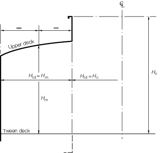
Figure 3.5.1 Heads for 'tween decks

Figure 3.5.2 Heads for watertight and deep tank bulkheads
5.2.2 The
following symbols and definitions apply in particular to the design
pressures for partially filled tanks:
Lpp and C
b as defined in Pt 3, Ch 1, 6.1 Principal particulars
|
b
|
= |
height
of internal primary bottom members, in metres |
|
F
|
= |
fill
height, in metres |
|
F
r
|
= |
effective filling ratio |
| = |

|
|
GM
|
= |
transverse
metacentric height, in metres, including free surface correction,
for the loading condition under consideration |
|
H
t
|
= |
tank depth, in metres, measured from the bottom of the tank
to the underside of the deck at side. In the case of holds, the depth
is measured from the inner bottom to the underside of the deck at
hatch side, except in double skin ships with hatch coaming in line
with the inner skin, in which case, the depth is measured to the top
of the hatch coaming |
|
n
|
= |
number
of internal primary bottom members |
|
L
s
|
= |
the effective horizontal free surface length, in metres, in
the direction of angular motion (i.e. tank breadth for roll, tank
length for pitch) |
|
S
nr
|
= |
ship's natural rolling period |
| = |
 seconds seconds
|
| = |
for ships for which either r or GM varies
significantly between loading conditions (for example, bulk carriers
and tankers, see
Pt 3, Ch 3, 1.1 Application 1.1.3), S
nr should be evaluated for each representative
loading condition considered
|
|
r
|
= |
radius
of gyration of roll, in metres, and may be taken as 0,34B
|
|
S
np
|
= |
ship's natural pitching period |
| = |
 seconds seconds
|
| = |
for ships for which either T or C
b varies
significantly between loading conditions (for example, bulk carriers
and tankers, see
Pt 3, Ch 3, 1.1 Application 1.1.3), S
np should be evaluated for each representative
loading condition considered
|
|
T
np
|
= |
fluid natural period of pitch |
| = |
 seconds seconds
|
|
T
nr
|
= |
fluid natural period of roll |
| = |
 seconds seconds
|
|
θmax
|
= |
maximum `lifetime' pitch angle, in degrees: |
| = |

|
|
φmax
|
= |
maximum
`lifetime' roll angle, in degrees: |
| = |

|
5.3 Stowage rate and design loads
5.3.1 Unless
it is specifically requested otherwise, the following standard stowage
rates are to be used:
-
1,39 m3/tonne
for weather or general cargo loading on deck and inner bottom.
-
0,975 m3/tonne
for liquid cargo of density of 1,025 tonne/m3 or less on
watertight and tank divisions. For liquid of density greater than
1,025 tonne/m3 the corresponding stowage rates are to be
adopted.
5.3.2 Proposals
to use a stowage rate greater than 1,39 m3/tonne for permanent
structure will require special consideration, and will normally be
accepted only in the case of special purpose designs such as fruit
carriers, etc.
5.4 Design pressure for partially filled tanks
5.4.1 When
partial filling of tanks or holds is contemplated for sea-going conditions,
the risk of significant loads due to sloshing induced by any of the
ship motions is to be considered. An initial assessment is to be made
to determine whether or not a higher level of sloshing investigation
is required, using the following procedure which corresponds to the
Level 1 investigation outlined in the SDA Procedure for Sloshing
loads and scantling assessment, on tanks partially filled with
liquids.
5.4.2 In general,
significant dynamic magnifications of the sloshing pressures are considered
unlikely for the following cases:
-
For internally
stiffened tanks:
-
Where two (or
more) deck girders (in the case of rolling) or deck transverses (in
the case of pitching) are located not more than 25 per cent of the
tank breadth or length respectively from the adjacent tank boundary,
and the fill level is greater than the tank depth minus the height
of the deck girders or transverses;
-
Where the
deck girders or transverses, at any location, are less than 10 per
cent of the tank depth, and the fill level is greater than the tank
depth minus the height of the deck girders or transverses;
-
Where the
fill level is less than the height of any bottom girders or transverses.
-
For smooth tanks:
where the fill level is less than 10 per cent or more than 97
per cent of the tank depth.
5.4.3 Significant
dynamic magnification of the fluid motions, and hence the sloshing
pressure, can occur if either of the following conditions exist:
-
The natural rolling period, Tnr, of the fluid and
the ship's natural rolling period, Snr, are within five seconds
of each other.
-
The natural pitching period, Tnp, of the fluid is
greater than a value of three seconds below the ship natural pitching period,
Snp.
These values define the limits of the critical fill range for
each tank.
5.4.5 The
natural periods of the ship for a given motion type are to be determined
for the service loading conditions agreed between the Shipbuilder
and Clasifications Register. From this aspect, the storm-ballast and the
segregated ballast conditions and the condition with all tanks partially
filled could be the most critical.
5.4.6 When
a ship is to be approved for Unrestricted Filling Levels - Unspecified
Loading Conditions, many arbitrary ship loading conditions are possible.
In order to cover the complete range of loading conditions, the fully
loaded and ballast conditions are to be considered. These two conditions
give an upper and lower limit for the possible range of natural periods
of the ship as shown in Figure 3.5.3 Natural periods diagrams.
Both the roll and pitch motion modes are to be examined.
Because of the unrestricted filling level requirement, the critical
sloshing ranges extend from [SnrBallast - 5] to [S
nrLoaded + 5] seconds in roll and from [SnpBallast - 3] to
[SnpLoaded] in pitch. Also, because of unrestricted filling levels,
the ship natural period range extends from [S
nBallast] to [S
nLoaded] for both pitch and roll.
For sloshing in the roll motion mode shown in Figure 3.5.3 Natural periods diagrams, the critical fill range extends from
F
1 to F4. All fill levels between F1 and
F4 are to be investigated:
- For fill levels between F1 and F2,
SnrBallast is to be used.
- For fill levels between F3 and F4,
SnrLoaded is to be used.
- For fill levels between F2 and F3,
Snr is to be equal to T
nr.
Similarly, for sloshing in the pitch motion mode shown in Figure 3.5.3 Natural periods diagrams, the critical fill range extends from
F1 to F4. All fill levels between
F1 and F4 are to be investigated.
- For fill levels between F1 and F2,
SnpBallast is to be used.
- For fill levels between F2 and F3,
Snp is to be equal to Tnp.
- For fill levels between F3 and F4,
Snp loaded is to be used.
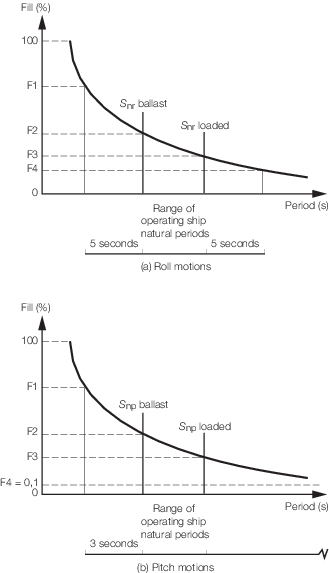
Figure 3.5.3 Natural periods diagrams
5.4.7 When
a ship is to be approved for Restricted Filling Levels - Unspecified
Loading Conditions, many arbitrary ship loading conditions are possible
within the restrictions imposed. In order to cover the complete range
of loading conditions, the fully loaded and ballast conditions are
to be considered. These two conditions give an upper and lower limit
for the possible range of ship natural period. It is recognised that
there might be ship natural period bands which will not be applicable
as a result of the limitations on the fill levels. However, it is
recommended that the Unrestricted Filling Levels - Unspecified Loading
Conditions procedure outlined in Pt 3, Ch 3, 5.4 Design pressure for partially filled tanks 5.4.6 be
applied.
5.4.8 When
a ship is to be approved for Unrestricted Filling Levels - Specified
Loading Conditions, each specified loading condition is to be examined
for the complete fill ranges to determine the critical sloshing fill
range for each tank in both roll and pitch motion modes.
5.4.9 When
a ship is to be approved for Restricted Filling Levels - Specified
Loading Conditions, each specified loading condition is to be examined
for the restricted fill ranges to determine the critical sloshing
fill range for each tank in both roll and pitch motion modes.
5.4.10 Where
the assessment indicates that all the intended fill levels are outside
the critical fill ranges and, therefore, significant sloshing will
not occur, no further evaluation is required with regard to sloshing
pressure. In such cases, the scantlings of the tank boundaries are
to be determined in accordance with the relevant Rule requirements.
5.4.12 The
structural capability of the tank boundaries to withstand the dynamic
sloshing pressures is to be examined. The magnitude of the predicted
loads, together with the scantling calculations may be required to
be submitted.
5.5 Flooded loads
5.5.1 The distance to the flooded load point, ZFD, is to be
calculated as follows;
where
Δ Th,t is the increase in draught due to heel and trim,
in metres
-
|
ΔTh,t |
= |
 |
Δ Th is the increase in draught due to heel, in
metres
Δ Tt is the increase in draught due to trim, in metres
- ΔTt = xttanφ
- xt is the distance from 0,5L to
the load point, in metres
- φ is the trim angle and is given by
Tf is the flooded draught, in metres, to be taken as
see also
Figure 3.5.4 Damage waterline at any location
5.5.2 For passenger ships, where the damage waterlines, see
Pt 3, Ch 1, 6.10 Damage waterlines, have not
been provided, the distance from the baseline to the deepest
equilibrium/intermediate waterline, whichever is the greater, and the intermittent
waterline can be estimated in accordance with Pt 3, Ch 3, 5.5 Flooded loads 5.5.1 using the
flooding angles and coefficients given in Table 3.5.3 Flooding angles and
coefficients for passenger ships. The flooded load point is to be measured
perpendicular to the damage waterline.
Table 3.5.2 Flooding angles and
coefficients
| Ship
type
|
Heel angle, θ
|
Trim coefficient, χ
|
Flooding coefficient,
ϕ
|
| Forward
|
Aft
|
Forward
|
Aft
|
| General cargo ships
|
30
|
2
|
3
|
1,10
|
1,10
|
| Container ships
|
30
|
1,5
|
2
|
1,05
|
1,05
|
| Ore carriers and bulk
carriers
|
30
|
3
|
1,5
|
1,05
|
1,10
|
| Ro-Ro cargo ships
|
30
|
3
|
2,5
|
1,10
|
1,30
|
| Gas Carriers
|
30
|
1
|
2,5
|
1,10
|
1,05
|
| Tankers
|
30
|
1
|
2
|
1,05
|
1,05
|
| Special purpose ships
carrying 200 personnel or fewer, see Note 1
|
12, see Note 2
|
2
|
2
|
1,10
|
1,10
|
| Other cargo ships
|
30
|
3
|
3
|
1,10
|
1,10
|
|
|
|
Note 2 The heel
angle is to be taken 7 degrees for locations aft of
0,5L
|
Table 3.5.3 Flooding angles and
coefficients for passenger ships
| Ship
type
|
Final/intermediate heel angle, θ
|
Intermittent heel angle, θ
|
Trim coefficient, χ
|
Flooding coefficient,
ϕ
|
| Forward
|
Aft
|
Forward
|
Aft
|
| Ro-Ro passenger
ships/ferries
|
15
|
26
|
3,5
|
3,5
|
1,15
|
1,15
|
| Multi-decked passenger
ships
|
15
|
22
|
0
|
0
|
1,15
|
1,15
|
| Other passenger ships and
ferries
|
15
|
22
|
0
|
0
|
1,15
|
1,15
|
| Special purpose ships
carrying more than 200 personnel, see Note
|
15
|
N/A
|
0
|
0
|
1,15
|
1,15
|
|
Note Special
purpose ships are as defined in the Code of Safety for
Special Purpose Ships – Resolution A.534(13)
|
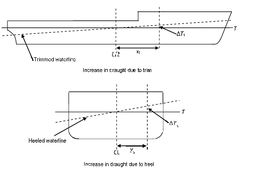
Figure 3.5.4 Damage waterline at any location
5.5.3 The heel angles and flooding coefficients given in Table 3.5.2 Flooding angles and
coefficients are based on one compartment damage. If required by the
Owner, additional flooding can be considered where the flooded load point is to be
determined based on the equilibrium damage waterline resulting from the damage
stability calculations, see
Pt 3, Ch 1, 6.10 Damage waterlines. The
flooded load point is to be measured perpendicular to the damage waterline.
5.5.4 Where the damage waterlines, see
Pt 3, Ch 1, 6.10 Damage waterlines, have been provided by
the designer, the methodology used to determine the damage waterlines is also to be
submitted as supporting information.
|