
Section
2 Steel hatch covers
2.1 General
2.1.2 The requirements of Pt 3, Ch 11, 2 Steel hatch covers
are applicable to hatch covers and coamings made of steel. Hatch covers of alternative
materials and innovative design will be specially considered.
2.1.5 Unless otherwise stated, the thicknesses referred to in the following
Sections are net thicknesses. The net thicknesses are the member thicknesses necessary
to obtain the minimum net scantlings required in this Section. The required gross
thicknesses are obtained by adding corrosion additions, t
c, given in Table 11.1.2 Corrosion addition t
c
. Strength calculations using grillage
analysis or FEM are to be performed with net scantlings.
2.1.6 Material class I is to be applied for top plate, bottom plate and primary
supporting members.
2.1.7 The
strength and closing arrangements of hatch covers are to comply with Pt 4, Ch 7, 12 Steel hatch covers in addition to the requirements
in this Chapter when hatch covers are subjected to internal ballast
or oil cargo pressure.
2.1.8 Hatch
covers are to comply with Pt 4, Ch 8, 11 Hatch covers in
addition to the requirements in this Chapter when containers are carried
on covers.
2.2 Stiffener arrangement
2.2.1 The
primary supporting members and secondary stiffeners of hatch covers
are to be continuous over the breadth and length of hatch covers,
as far as practical. When this is impractical, sniped end connections
are not to be used and appropriate arrangements are to be adopted
to ensure sufficient load-carrying capacity.
2.2.2 The
spacing of primary supporting members parallel to the direction of
secondary stiffeners is not to exceed one third of the span of primary
supporting members. When strength calculation is carried out by FE
analysis using plane strain or shell elements, this requirement can
be waived.
2.2.3 Secondary stiffeners of hatch coamings are to be continuous over the breadth and length
of hatch coamings.
2.2.4 Supporting members in way of cut-outs are to have sufficient shear area.
2.3 Load model
2.3.1 The
structural assessment of hatch covers is to be carried out using the
design loads defined in this Section. The following symbols and definitions
are applicable to this Section:
|
x
|
= |
longitudinal co-ordinate measured from the AP to mid point of
assessed structural member |
|
T
fb
|
= |
draught, in metres, corresponding to the assigned summer load
line |
|
h
N
|
= |
standard superstructure height in metres |
|
|
= |
1,05 + 0,01L
L, 1,8 ≤ h
N ≤ 2,3 |
where
2.3.2 The
vertical weather design pressure, p
H, in kN/m2, on the hatch cover panels is to be taken from Table 11.2.1 Design pressure p
H of weather deck hatches . When cargo is carried
on the cover, cargo loads according to Pt 3, Ch 11, 2.3 Load model 2.3.4, Pt 3, Ch 11, 2.3 Load model 2.3.5 and Pt 4, Ch 8, 11.2 Direct calculations are to be considered.
The vertical weather design load needs not to be combined with the
cargo load. For 'tween deck hatch covers not exposed to weather load,
the structural assessment is to be carried out using the cargo loads
defined in Pt 3, Ch 11, 2.3 Load model 2.3.4 and Pt 3, Ch 11, 2.3 Load model 2.3.5. Covers carrying wheeled
vehicles are also to comply with Pt 3, Ch 9, 3 Decks loaded by wheeled vehicles and
where it is proposed to provide a helicopter landing area, covers
are also to comply with Pt 3, Ch 9, 5 Helicopter landing areas.
Where an increased freeboard is assigned, the design load for hatch
covers according to Table 11.2.1 Design pressure p
H of weather deck hatches on
the actual freeboard deck may be as required for a superstructure
deck, provided the summer freeboard is such that the resulting draught
will not be greater than that corresponding to the minimum freeboard
calculated from an assumed freeboard deck situated at a distance at
least equal to the standard superstructure height, h
N,
below the actual freeboard deck, see
Figure 11.2.2 Positions 1 and 2 for an increased freeboard.
Table 11.2.1 Design pressure p
H of weather deck hatches
Position
(see Note)
|
p
H, in kN/m2
|
| 1
|
 ≤ 0,75 ≤ 0,75
|
0,75 <  ≤ 1,0 ≤ 1,0
|
|
|
for 24 m
≤ L
L ≤ 100 m
|
|
|
|
on freeboard
deck
|
|
|
|
upon exposed superstructure decks
located at least one superstructure standard height above the freeboard deck
 (1,15L
L + 116) (1,15L
L + 116)
|
|
|
for
L
L > 100 m
|
|
|
3,5g
|
on freeboard deck for type B ships
according to ICLL
|
|
|
|
on freeboard deck for ships with less
freeboard than type B according to ICLL
L
1 = L
L but not more than 340 m
|
|
|
|
upon exposed superstructure decks
located at least one superstructure standard height above the freeboard deck
3,5g
|
| 2
|
for 24 m
≤ L
L ≤ 100 m
|
|
|
 (1,1L
L + 87,6) (1,1L
L + 87,6)
|
|
|
for
L
L > 100 m
|
|
|
2,6g
|
|
|
upon
exposed superstructure decks located at least one superstructure standard
height above the lowest Position 2 deck
2,1g
|
| Symbols
|
|
g
|
= |
acceleration due to gravity, 9,81 m/s2
|
|
|
|
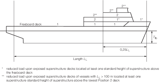
Figure 11.2.1 Positions 1 and 2
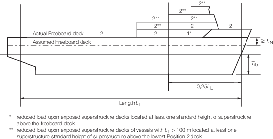
Figure 11.2.2 Positions 1 and 2 for an increased freeboard
2.3.3 The horizontal weather design pressure, in kN/m 2, for determining
the scantlings of outer edge girders (skirt plates) of weather deck hatch covers and of
hatch coamings is:
|
p
A
|
= |
a
c (b
c
L
f – z) kN/m2
|
|
f
|
= |
 + 4,1 for L < 90 m + 4,1 for L < 90 m
|
| = |
10,75 –  for 90 m ≤ L < 300 m for 90 m ≤ L < 300 m |
| = |
10,75 for 300 m ≤ L < 350
m
|
| = |
10,75 –  for 350 m ≤ L ≤ 500 m for 350 m ≤ L ≤ 500 m
|
|
c
L
|
= |
 for L < 90 m for L < 90 m
|
| = |
1 for L
> 90 m |
|
a
|
= |
20 +  for unprotected front coamings and hatch cover skirt plates for unprotected front coamings and hatch cover skirt plates
|
|
a
|
= |
10
+  for unprotected front coamings and hatch cover skirt plates,
where the distance from the actual freeboard deck to the summer load
line exceeds the minimum non-corrected tabular freeboard according
to ICLL by at least one standard superstructure height h
N for unprotected front coamings and hatch cover skirt plates,
where the distance from the actual freeboard deck to the summer load
line exceeds the minimum non-corrected tabular freeboard according
to ICLL by at least one standard superstructure height h
N
|
|
a
|
= |
5
+  for side and protected front coamings and hatch cover
skirt plates for side and protected front coamings and hatch cover
skirt plates
|
|
a
|
= |
7
+  – 8 – 8  for aft ends of coamings and aft hatch cover skirt plates
abaft amidships for aft ends of coamings and aft hatch cover skirt plates
abaft amidships
|
|
a
|
= |
5
+  – 4 – 4  for aft ends of coamings and aft hatch cover skirt plates
forward of amidships for aft ends of coamings and aft hatch cover skirt plates
forward of amidships
|
|
L
1
|
= |
L, need not be taken greater than 300 m
|
|
b
|
= |
 for for  < 0,45 < 0,45
|
|
b
|
= |
 for for  ≥ 0,45 ≥ 0,45
|
| = |
0,6 ≤ C
b ≤ 0,8,
when determining scantlings of aft ends of coamings and aft hatch
cover skirt plates forward of amidships, C
b need
not be taken less than 0,8
|
|
x’
|
= |
distance,
in metres, between the transverse coaming or hatch cover skirt plate
considered and aft end of the length
L.
When determining side coamings or side hatch cover skirt plates, the
side is to be subdivided into parts of approximately equal length,
not exceeding 0,15L each, and x’ is
to be taken as the distance between aft end of the length L and
the centre of each part considered
|
|
z
|
= |
vertical
distance in metres from the summer load line to the mid point of stiffener
span, or to the middle of the plate field |
|
c
|
= |
0,3
+ 0,7 
|
|
b'
|
= |
breadth
of coaming in metres at the position considered |
|
B'
|
= |
actual
maximum breadth of ship in metres on the exposed weather deck at the
position considered b'/B' is not to be taken less than
0,25
|
The design pressure p
A is
not to be taken less than the minimum values given in Table 11.2.2 Minimum design load, p
Amin
.
Table 11.2.2 Minimum design load, p
Amin
|
L
|
p
Amin, kN/m2
|
|
|
For unprotected fronts
|
Elsewhere
|
| ≤ 50
|
30
|
15
|
| > 50
|
25 + 
|
12,5 + 
|
| < 250
|
|
|
| ≥ 250
|
50
|
25
|
2.3.4 The pressure on hatch covers due to distributed cargo loads p
L, in kN/m2, resulting from heave and pitch (i.e. ship in upright
condition), is to be determined according to the following formula:
where
|
p
c
|
= |
uniform cargo load, in kN/m2
|
|
a
v
|
= |
vertical acceleration addition as follows: |
|
a
v
|
= |
F
m
|
|
F |
= |
0,11 
|
|
m
|
= |
m
0 – 5 (m
0 – 1)  for 0 ≤ for 0 ≤  ≤ 0,2 ≤ 0,2 |
|
|
= |
1,0 for 0,2 <  ≤ 0,7 ≤ 0,7
|
|
|
= |

|
|
m
0
|
= |
1,5 + F
|
|
v
0
|
= |
Maximum speed at summer load line draught, v
0 is
not to be taken less than  , in knots. , in knots.
|
2.3.5 The point load due to a concentrated force, P, in kN resulting from
heave and pitch is to be determined as follows:
|
P
s
|
= |
single force, in kN. |
2.3.7 In addition to the loads defined in this Section, hatch covers are loaded
in the ship's transverse direction by forces due to elastic deformations of the ship's
hull. Hatch covers may be required to be designed such that the sum of stresses does
not exceed the permissible values given in Pt 3, Ch 11, 2.4 Allowable stress and deflection 2.4.1.
2.4 Allowable stress and deflection
2.4.1 The equivalent stress, σv, in steel hatch cover structures
related to the net thickness shall not exceed 0,8σo, where
σo is the minimum yield stress, in N/mm2, of the
material. For design loads according to Pt 3, Ch 11, 2.3 Load model 2.3.3 to Pt 3, Ch 11, 2.3 Load model 2.3.7 and Pt 4, Ch 8, 11.2 Direct calculations, the equivalent stress, σv, related to the
net thickness shall not exceed 0,9σo when the stresses are assessed by means
of FEM.
For grillage analysis, the equivalent stress may be taken as follows:
|
σ v
|
= |
 , in N/mm2 , in N/mm2
|
|
σ |
= |
normal
stress in N/mm2
|
|
τ |
= |
shear stress
in N/mm2
|
For FEM calculations, the equivalent stress may be
taken as follows:
|
σ v
|
= |
 , N/mm2 , N/mm2
|
|
σ x
|
= |
normal stress, in N/mm2, in x-direction
|
|
σ y
|
= |
normal stress, in N/mm2, in y-direction
|
|
τ |
= |
shear stress,
in N/mm2, in the x-y plane
|
Indices x and y are coordinates of a two-dimensional
Cartesian system in the plane of the considered structural element.
In the case of FEM calculations using shell or plane strain elements, the
stresses are to be read from the centre of the individual element. It is to be
recognised that in particular at flanges of unsymmetrical girders, the evaluation of
stress from the element centre may lead to non-conservative results. Thus, a
sufficiently fine mesh is to be applied in these cases. Where shell elements are used,
the stresses are to be evaluated at the mid plane of the element.
Stress concentrations are to be considered by examining design details or
FE analysis. FEM calculations are to be carried out in accordance with the ShipRight
procedure Assessment of Steel Hatch Covers using Finite Element Analysis.
2.4.2 The vertical deflection of primary supporting members due to the vertical
weather design load according to Pt 3, Ch 11, 2.3 Load model 2.3.2, is to be not more than 0,0056 lg
where lg is the greatest span of primary supporting members.
Note Where hatch covers are arranged for
carrying containers and mixed stowage is allowed, i.e. a 40’-container stowed on top
of two 20’-containers, particular attention should be paid to the deflections of
hatch covers. Furthermore the possible contact of deflected hatch covers with in-hold
cargo has to be avoided.
For 'tween deck hatch covers not exposed to the vertical weather
design load according to Pt 3, Ch 11, 2.3 Load model 2.3.2,
the vertical deflection of primary supporting members due to the cargo
loads according to Pt 3, Ch 11, 2.3 Load model 2.3.4, Pt 3, Ch 11, 2.3 Load model 2.3.5 and Pt 4, Ch 8, 11.2 Direct calculations is to be not more
than 0,007l
g where l
g is
the greatest span of primary supporting members.
2.5 Local net plate thickness
2.5.1 The
local net plate thickness, t, in mm, of the hatch cover
top plating is not to be less than:
and to be not less than 1 per cent of the spacing of the stiffener or 6 mm, whichever is
greater
|
F
p
|
= |
factor for combined membrane and bending response |
| = |
1,5 in general |
| = |
1,9  , for , for  ≥ 0,8 ≥ 0,8 |
for the attached plate flange of primary supporting members
|
s
|
= |
stiffener
spacing, in mm |
|
σ0 |
= |
minimum yield stress, in N/mm2, of the material |
For flange plates under compression, sufficient buckling
strength according to Pt 3, Ch 11, 2.11 Buckling strength of hatch cover structures is
to be demonstrated.
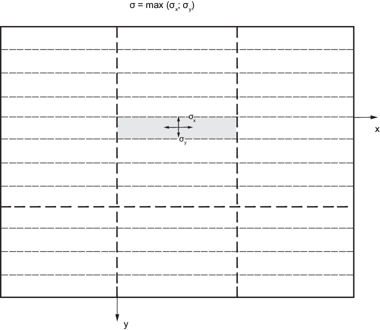
Figure 11.2.3 Determination of normal stress of
the hatch cover plating
2.6 Local plate thickness of hatch covers for wheel loading and helicopter
landing
2.7 Lower plating of double skin hatch covers and box girders
2.7.1 The thickness to fulfil the strength requirements is to be obtained from the
calculation according to Pt 3, Ch 11, 2.10 Strength calculations under consideration of permissible stresses
according to Pt 3, Ch 11, 2.4 Allowable stress and deflection 2.4.1. When the lower plating is taken into account as a
strength member of the hatch cover, the net thickness, in mm, of lower plating is to be
taken not less than 5 mm. When project cargo is intended to be carried on a hatch cover,
the net thickness must not be less than:
|
s
|
= |
stiffener
spacing, in mm. |
Note Project cargo means especially large or bulky cargo lashed to the hatch cover.
Examples are parts of cranes or wind power stations, turbines, etc. Cargoes that can
be considered as uniformly distributed over the hatch cover, e.g. timber, pipes or
steel coils, need not be considered as project cargo.
When the lower plating is not considered as a strength member of the hatch cover, the
thickness of the lower plating is to be specially considered.
2.8 Net scantling of secondary stiffeners
2.8.1 The net section modulus, Z, and net shear area,
As, of uniformly loaded hatch cover stiffeners constrained at both
ends is not to be less than:
where
 |
= |
secondary
stiffener span, in metres, to be taken as the spacing, in metres,
of primary supporting members or the distance between a primary supporting
member and the edge support, as applicable |
|
s
|
= |
secondary
stiffener spacing, in mm |
|
p
|
= |
pressure p
H and p
L, in kN/m2, as defined in Pt 3, Ch 11, 2.3 Load model 2.3.2 and Pt 3, Ch 11, 2.3 Load model 2.3.4 respectively. |
|
σo |
= |
minimum yield stress, in N/mm2, of the material, see
Pt 3, Ch 11, 2.4 Allowable stress and deflection 2.4.1 |
For secondary stiffeners of lower plating of double skin hatch covers, requirements
mentioned above are not applicable due to the absence of lateral loads.
The net thickness, in mm, of the stiffener web, except of u-beams/trapeze stiffeners, is
to be taken not less than 4 mm.
2.8.2 The
net section modulus of the secondary stiffeners is to be determined,
based on an attached plate width assumed equal to the stiffener spacing.
2.8.3 For flat bar secondary stiffeners and buckling stiffeners, the ratio
h/t
w is to be not greater than 15k
0,5
where
|
h
|
= |
height
of the stiffener |
|
t
w
|
= |
net thickness of the stiffener |
2.8.4 Stiffeners parallel to primary supporting members and arranged within the
effective breadth according to Pt 3, Ch 11, 2.10 Strength calculations must be continuous when crossing primary supporting
members and may be considered when calculating the cross-sectional properties of primary
supporting members. It is to be verified that the combined stress of those stiffeners,
induced by the bending of primary supporting members and lateral pressures, does not
exceed the permissible stresses according to Pt 3, Ch 11, 2.4 Allowable stress and deflection 2.4.1. The requirements of this paragraph are not applied
to stiffeners of lower plating of double skin hatch covers if the lower plating is not
considered as strength member.
2.9 Net scantling of primary supporting members
2.9.3 The
net thickness, t, in mm, of webs of primary supporting
members is not to be less than:
-
0,0065s,
in mm
-
5 mm
where
|
s
|
= |
stiffener
spacing, in mm. |
2.9.5 The
net thickness, t, in mm, of the outer edge girders exposed
to wash of sea is not to be less than the largest of the following
values:
-
0,0158s

-
0,0085s mm
-
5 mm
where
|
s
|
= |
stiffener
spacing, in mm. |
2.9.6 The
stiffness of edge girders is to be sufficient to maintain adequate
sealing pressure between securing devices. The moment of inertia,
in cm4, of edge girders is not to be less than:
 |
= |
6q
s
SD
4
|
|
q
|
= |
packing
line pressure, in N/mm, minimum 5 N/mm |
|
s
SD
|
= |
spacing, in metres, of securing devices. |
2.10 Strength calculations
2.10.2 The effective cross-sectional properties for calculation by grillage
analysis are to be determined considering the effective breadth. Cross-sectional areas
of secondary stiffeners parallel to the primary supporting member under consideration
within the effective breadth can be included, see
Figure 11.2.5 Stiffening parallel to web of primary supporting member. The effective breadth of plating, e
m, of primary supporting members is to be determined according to Table 11.2.3 Effective breadth e
m of plating of primary supporting members , considering the type of loading. Special
calculations may be required for determining the effective breadth of one-sided or
non-symmetrical flanges. The effective cross-sectional area of plates is not to be less
than the cross-sectional area of the face-plate. For flange plates under compression
with secondary stiffeners perpendicular to the web of the primary supporting member, the
effective width is to be determined according to Pt 3, Ch 11, 2.14 Effective width of top and lower hatch cover plating 2.14.1.
Table 11.2.3 Effective breadth e
m of plating of primary supporting members
 /e /e
|
0
|
1
|
2
|
3
|
4
|
5
|
6
|
7
|
≥8
|
|
e
m1/e
|
0
|
0,36
|
0,64
|
0,82
|
0,91
|
0,96
|
0,98
|
1,00
|
1,00
|
|
e
m2/e
|
0
|
0,20
|
0,37
|
0,52
|
0,65
|
0,75
|
0,84
|
0,89
|
0,90
|
| Symbols
|
|
e
m1
|
is
to be applied where primary supporting members are loaded by uniformly
distributed loads or else by no fewer than six equally spaced single
loads
|
|
e
m2
|
is
to be applied where primary supporting members are loaded by three or fewer
single loads. Intermediate values may be obtained by direct
interpolation
|

|
length of zero-points of bending moment curve:
|
|
|
 = =  0 for simply supported primary supporting
members 0 for simply supported primary supporting
members
|
|
|
 = 0,6 = 0,6 0 for primary supporting members with both ends
constrained 0 for primary supporting members with both ends
constrained
|
| where
|
|
 0 0
|
is
the unsupported length of the primary supporting member
|
|
e
|
width of plating supported, measured from centre to centre of the adjacent
unsupported fields
|
2.10.3 FEM calculations are to be done in accordance with the ShipRight SDA Procedure,
Assessment of Steel Hatch Covers Using Finite Element Analysis.
2.11 Buckling strength of hatch cover structures
2.11.1 For
hatch cover structures, sufficient buckling strength is to be demonstrated.
|
a
|
= |
length
of the longer side of a single plate field, in mm |
|
b
|
= |
breadth
of the shorter side of a single plate field, in mm |
|
α |
= |
aspect
ratio of single plate field |
|
n
|
= |
number
of single plate field breadths within the partial or total plate field |
|
t
|
= |
net
plate thickness, in mm |
|
σx
|
= |
membrane stress, in N/mm2, in x-direction
|
|
σy
|
= |
membrane stress, in N/mm2, in y-direction
|
|
τ |
= |
shear stress,
in N/mm2, in the x-y plane
|
|
E
|
= |
modulus
of elasticity, in N/mm2, of the material
|
|
|
= |
2,06 x 10⁵ N/mm2 for steel
|
|
σo
|
= |
minimum yield stress, in N/mm2, of the material. |
Compressive and shear stresses are to be taken positive,
tension stresses are to be taken negative.
If stresses
in the x- and y-direction already contain the Poisson effect (calculated
using FEM), the following modified stress values may be used. Both
stresses σ
x * and σ
y *
are to be compressive stresses, in order to apply the stress reduction
according to the following formulae.
|
σx
*, σy
*
|
= |
stresses containing the Poisson effect where compressive stress
fulfils the condition
σy
* < 0,3σx
*, then σy = 0 and σx = σx
*
where compressive stress fulfils the condition
σx
* < 0,3σy
*, then σx = 0 and σy = σy
*
|
|
σe
|
= |
reference stress, in N/mm2, taken equal to
|
|
|
= |
0,9E

|
|
ψ |
= |
edge stress
ratio taken equal to |
|
|
= |

|
where
|
σ1
|
= |
maximum compressive stress |
|
σ2
|
= |
minimum compressive stress or tension stress |
|
S
|
= |
safety
factor (based on net scantling approach), taken equal to |
|
λ |
= |
reference
degree of slenderness, taken equal to: |
|
|
= |

|
Table 11.2.4 Correction factor F
1
| Stiffeners sniped at both
ends
|
1,00
|
|
Guidance values, see
Note 1, where both ends
are effectively
connected
to adjacent structures
|
1,05
|
for flat bars
|
| 1,10
|
for bulb sections
|
| 1,21
|
for angle and tee-sections
|
| 1,30
|
for u-type sections, see Note
2, and girders of high rigidity
|
| An
average value of F1, is to be used for plate panels having
different edge stiffeners
|
Note
1. Exact values may be determined by
direct calculations.
Note
2. A higher value, but not greater than
2,0, may be taken if it is verified by a buckling strength check of
the partial plate field using non-linear FEA. The calculations are to
be submitted to LR for approval.
|
Table 11.2.5 Coefficients e
1, e
2, e
3 and factor B
| Exponents e
1 to e
3 and factor B
|
Plate panel
|
|
e
1
|
1 + κ
x
4
|
|
e
2
|
1 + κ
y
4
|
|
e
3
|
1 + κ
x
κ
y
κ
τ
2
|
B
σ
x and σ
y positive (compression stress)
|
(κ
x
κ
y)5
|
|
B
σ
x or σ
y negative (tension stress)
|
1
|
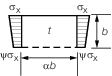
2.11.2 Proof
is to be provided that the following condition is complied with for
the single plate field a
b:
The first two terms and the last term of the above
condition shall not exceed 1,0.
The reduction factors κ
x, κ
y and κ
τ are given in Table 11.2.6 Buckling and reduction factors for
plane elementary plate panels.
Where σ
x ≤ 0 (tension
stress), κ
x = 1,0.
Where σ
y ≤ 0 (tension stress), κ
y =
1,0.
The exponents e
1, e
2 and e
3 as well as the factor B are
to be taken as given by Table 11.2.5 Coefficients e
1, e
2, e
3 and factor B
.
Table 11.2.6 Buckling and reduction factors for
plane elementary plate panels
| Buckling load case
|
Edge
stress ratio ψ
|
Asp. ratio

|
Buckling
factor K
|
Reduction factor κ
|
| 1
|
|
1 ≥ ψ ≥
0
|
α ≥ 1
|
|
κx = 1 for λ ≤ λc
|
|
0 > ψ
> –1
|
K
= 7,63 – ψ (6,26 – 10ψ)
|
|
| ψ ≤ –1
|
K = 5,975 (1 – ψ)2
|
c = (1,25 – 0,12ψ) ≤ 1,25
|
|
|
| 2
|
|
1 ≥ ψ ≥ 0
|
α ≥ 1
|
|

|

|
c = (1,25 – 0,12ψ) ≤ 1,25
|
|
|
|
 for λ < λ
c for λ < λ
c
|
|
|
|
0 > ψ > –1
|
1 ≤ α ≤ 1,5
|
|
R = 0,22 for λ ≥ λ
c
|
|
|
|
|
|
|
|
|
|
|
|
α > 1,5
|
|
λ
p
2 = λ
2 – 0,5 for 1 ≤ λ
p
2 ≤ 3
|
|
|
|
|
|
|
|
ψ ≤ –1
|
|
|
|
|
|
|
|
|
|
| 3
|
|
1 ≥ ψ ≥
0
|
α > 0
|
|
κ
X = 1 for λ ≤ 0,7
|

|
0 > ψ
≥ –1
|
|
 for λ > 0,7 for λ > 0,7
|
| 4
|

|
1 ≥ ψ ≥
–1
|
α > 0
|
|
| 5
|
|
—
|
|
K = K
τ

|
κ
τ = 1 for λ ≤ 0,84
|

|
α ≥ 1
|
|
 for λ > 0,84 for λ > 0,84
|
|
|
|
0 <
α < 1
|
|
| Explanations for boundary conditions
|
|

|
plate
edge free
plate edge simply supported
|
2.12 Webs and flanges of primary supporting members
2.13 Longitudinal and transverse secondary stiffeners
2.14 Effective width of top and lower hatch cover plating
2.14.1 For
demonstration of buckling strength according to Pt 3, Ch 11, 2.15 Lateral buckling of secondary stiffeners and Pt 3, Ch 11, 2.16 Torsional buckling of secondary stiffeners, the effective width of plating
may be determined by the following formulae:
|
b
m
|
= |
κx
b for longitudinal stiffeners
|
|
a
m
|
= |
κy
a for transverse stiffeners |
see also
Figure 11.2.4 General arrangement of panel.
The effective width of plating is not
to be taken greater than the value obtained from Pt 3, Ch 11, 2.10 Strength calculations 2.10.2.
The effective
width e'
m of stiffened flange plates of primary
supporting members may be determined as follows:
(a) Stiffening parallel to web of primary supporting member:
(b) Stiffening perpendicular to web of primary supporting member:
For b ≥ e
m or a < e
m, respectively, b and a are to be exchanged.
a
m and b
m for
flange plates are in general to be determined for ψ = 1.
Scantlings of plates and stiffeners are in general to be determined
according to the maximum stresses σx(y)
at webs of primary supporting member and stiffeners, respectively.
For stiffeners with spacing b under compression arranged
parallel to primary supporting members, no value less than 0,25σo shall be inserted for σx(y=b).
The stress distribution between two primary supporting members
can be obtained by the following formula:
|
σx(y)
|
= |

|
where
|
c
1
|
= |

|
|
c
2
|
= |

|
|
e
m1”
|
= |
proportionate effective breadth e
m1 or
proportionate effective width e
m1’ of
primary supporting member 1 within the distance e, as
appropriate
|
|
e
m2”
|
= |
proportionate effective breadth e
m2 or
proportionate effective width e
m2 ’
of primary supporting member 2 within the distance e,
as appropriate
|
|
σx1, σx2
|
= |
normal stresses in flange plates of adjacent
primary supporting member 1 and 2 with spacing e, based
on cross-sectional properties considering the effective breadth or
effective width, as appropriate
|
|
y
|
= |
distance
of considered location from primary supporting member 1 |
Shear stress distribution in the flange plates may be assumed linearly.
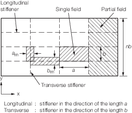
Figure 11.2.4 General arrangement of panel
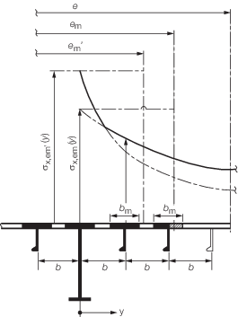
Figure 11.2.5 Stiffening parallel to web of primary supporting member
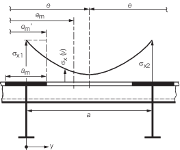
Figure 11.2.6 Stiffening perpendicular to web of primary supporting member
2.15 Lateral buckling of secondary stiffeners
2.15.1 The secondary stiffeners are to comply with the following criteria:
where
|
σa
|
= |
uniformly distributed compressive stress, in N/mm2, in
the direction of the stiffener axis |
|
σa
|
= |
σx for longitudinal stiffeners |
|
σa
|
= |
σy for transverse stiffeners |
|
σb
|
= |
bending stress, in N/mm2, in the stiffener |
| = |
 |
|
M
0
|
= |
bending moment, in Nmm, due to the deformation w of
stiffener, taken equal to: |
|
M
0
|
= |

|
|
M
1
|
= |
bending moment, in Nmm, due to the lateral load p equal to: |
|
M
1
|
= |
 for longitudinal stiffeners for longitudinal stiffeners |
|
M
1
|
= |
 for transverse stiffeners for transverse stiffeners |
- n is to be taken equal to 1 for ordinary transverse stiffeners
|
p
|
= |
lateral load, in kN/m2
|
|
F
Ki
|
= |
ideal buckling force, in N, of the stiffener |
|
F
Kix
|
= |
 for longitudinal stiffeners for longitudinal stiffeners |
|
F
Kiy
|
= |
 for transverse stiffeners for transverse stiffeners |
 x, x,  y y
|
= |
net moments of inertia, in cm4, of the longitudinal or
transverse stiffener, including effective width of attached plating according to
Pt 3, Ch 11, 2.14 Effective width of top and lower hatch cover plating 2.14.1.  x and x and  y are to comply with the following criteria: y are to comply with the following criteria: |
|
p
z
|
= |
nominal lateral load, in N/mm2, of the stiffener due to
σx, σy and τ |
|
p
zx
|
= |
 for longitudinal stiffeners for longitudinal stiffeners |
|
p
zy
|
= |
 for transverse stiffeners for transverse stiffeners |
|
σxl
|
= |

|
|
c
x, c
y
|
= |
factor taking into account the stresses perpendicular to the
stiffener's axis and distributed variably along the stiffener's length |
|
|
= |
0,5 (1 + ψ) for 0 ≤ ψ ≤ 1 |
|
|
= |

|
|
A
x, A
y
|
= |
net sectional area, in mm2, of the longitudinal or
transverse stiffener, respectively, without attached plating |
|
τ
1
|
= |
 |
- for longitudinal stiffeners:
  - for transverse stiffeners:
 
|
w
|
= |
w
0 + w
1
|
|
w
0
|
= |
assumed imperfection, in mm |
NOTE
For stiffeners sniped at both ends, w
0 must not be taken less than the distance from the mid point of plating to
the neutral axis of the profile, including effective width of plating.
|
w
1
|
= |
deformation of stiffener, in mm, at midpoint of stiffener span due
to lateral load p
|
In the case of uniformly distributed load, the following values for
w
1 may be used:
|
w
1
|
= |
 for longitudinal stiffeners for longitudinal stiffeners |
|
w
1
|
= |
 for transverse stiffeners for transverse stiffeners |
|
c
f
|
= |
elastic support provided by the stiffener, in N/mm2
|
-
For longitudinal stiffeners:
|
c
fx
|
= |

|
|
c
px
|
= |

|
|
c
xa
|
= |
 for a ≥ 2b for a ≥ 2b
|
|
c
xa
|
= |
 for a < 2b for a < 2b
|
-
For transverse stiffeners:
|
c
fy
|
= |

|
|
c
py
|
= |

|
|
c
ya
|
= |
 for n b ≥ 2a for n b ≥ 2a
|
|
c
ya
|
= |
 for n b < 2a for n b < 2a
|
|
c
s
|
= |
factor accounting for the boundary conditions of the transverse
stiffener |
| = |
1,0 for simply supported stiffeners |
| = |
2,0 for partially constrained stiffeners |
|
Z
st
|
= |
net section modulus of stiffener (longitudinal or transverse),
in cm3, including effective width of plating according to Pt 3, Ch 11, 2.14 Effective width of top and lower hatch cover plating 2.14.1. |
If no lateral load p is acting, the bending stress
σb is to be calculated at the mid point of the stiffener span for
that fibre which results in the largest stress value. If a lateral load p
is acting, the stress calculation is to be carried out for both fibres of the
stiffener's cross-sectional area (if necessary for the biaxial stress field at the
plating side).
2.16 Torsional buckling of secondary stiffeners
2.16.1 The
longitudinal secondary stiffeners are to comply with the following
criteria:
where
|
κ
T
|
= |
coefficient taken equal to: |
|
κ
T
|
= |
1,0 for λT ≤ 0,2
|
|
κ
T
|
= |

|
|
Φ |
= |
0,5 (1 + 0,21
(λ
T – 0,2) + λ
T
2)
|
|
λ
T
|
= |
reference degree of slenderness taken equal to: |
|
λ
T
|
= |

|
|
σKiT
|
= |

|
For  P, P,  T, T,  ω,
see
Figure 11.2.7 Dimensions of stiffener and Table 11.2.7 Moments of inertia ω,
see
Figure 11.2.7 Dimensions of stiffener and Table 11.2.7 Moments of inertia
 P P
|
= |
net
polar moment of inertia of the stiffener, in cm4, related
to the point C
|
 T T
|
= |
net
St.Venant's moment of inertia of the stiffener, in cm4
|
 ω ω
|
= |
net sectorial moment of inertia of the stiffener, in cm6,
related to the point C
|

|
= |
degree of fixation taken
equal to: |

|
= |

|
|
t
w
|
= |
net web thickness, in mm |
|
b
f
|
= |
flange breadth, in mm |
|
t
f
|
= |
net flange thickness, in mm |
|
A
w
|
= |
net web area equal to: A
w = h
w
t
w
|
|
A
f
|
= |
net flange area equal to: A
f = b
f
t
f
|
|
e
f
|
= |

|
|
b
|
= |
stiffener
spacing, in mm |
|
t
|
= |
local
net plate thickness of the attached plate, in mm. |
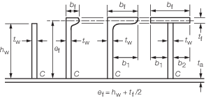
Figure 11.2.7 Dimensions of stiffener
Table 11.2.7 Moments of inertia
2.16.2 For
transverse secondary stiffeners loaded by compressive stresses and
which are not supported by longitudinal stiffeners, sufficient torsional
buckling strength is to be demonstrated analogously in accordance
with this sub-Section.
2.17 Pontoon covers
2.17.1 The
structural assessment of pontoon covers, as defined in Pt 3, Ch 11, 1.1 Application 1.1.5.(b), is to be carried out
by direct calculations, which are to be submitted for approval, using
the minimum design pressures acting on the hatch covers defined in Table 11.2.8 Pontoon cover minimum design
pressures. The permissible stress,
deflection and buckling criteria are given in Table 11.2.10 Steel pontoon cover permissible
stress, deflection and buckling criteria.
Table 11.2.8 Pontoon cover minimum design
pressures
| For
ships of 100 m in length and above:
|
| (a)
|
Position 1 hatch covers located in the
forward quarter of the ship's length shall be designed for wave pressures at
the forward perpendicular, calculated from the following equation:
|
|
|
Minimum design pressure, p =
49,05 + 9,81 (L
H–100)a in kN/m2 where
|
|
|
L
H is L for ships of not more than 340 m but not less than
100 m in length and equal to 340 m for ships of more than 340 m in
length:
|
a
|
= |
0,0074 for Type B freeboard ships |
| = |
0,0363 Ships assigned reduced freeboard |
|
|
|
The pressure, p, is to be
reduced linearly to 34,3 kN/m2 at the end of the forward
quarter's length, as shown in Table 11.2.9 Summary of pontoon cover minimum
design pressures
|
|
|
The design pressure used for each
hatch cover panel shall be that determined at its mid point location:
|
| (b)
|
All other position 1 hatch covers
shall be designed to 34,3 kN/m2
|
| (c)
|
Position 2 hatch covers
shall be designed to 25,5 kN/m2
|
| (d)
|
Where a position 1
hatchway is located at least one superstructure standard height higher than
the freeboard deck, it may be designed to 34,3 kN/m2
|
| For ships 24 m in length:
|
| (a)
|
Position 1 hatch covers
located in the forward quarter of the ship's length shall be designed for
wave pressures of 23,8 kN/m2 at the forward perpendicular and
reduced linearly to 19,6 kN/m2 at the end of the forward
quarter's length, as shown in Table 11.2.9 Summary of pontoon cover minimum
design pressures.
The design
pressure used for each hatch cover panel shall be that determined at its mid
point location
|
| (b)
|
All other position 1
hatch covers shall be designed to 19,6 kN/m2
|
| (c)
|
Position 2 hatch covers
shall be designed to 14,7 kN/m2
|
| (d)
|
Where a position 1
hatchway is located at least one superstructure standard height higher than
the freeboard deck, it may be designed to 19,6 t/m2
|
| For ships between 24 m and 100 m in length, and for positions
between FP and 0,25L, wave pressures shall be obtained by linear
interpolation of the values shown in Table 11.2.9 Summary of pontoon cover minimum
design pressures
|
Table 11.2.9 Summary of pontoon cover minimum
design pressures
| Deck
location
|
Longitudinal position
|
|
|
FP
|
0,25L
|
Aft of 0,25L
|
|
L>100 m
|
| Freeboard deck
|
Equation given in Table 11.2.8 Pontoon cover minimum design
pressures
|
34,3 kN/m2
|
34,3 kN/m2
|
| Superstructure
deck
|
34,3 kN/m2
|
25,5 kN/m2
|
|
|
L =100 m
|
| Freeboard deck
|
49,05 kN/m2
|
34,3 kN/m2
|
34,3 kN/m2
|
| Superstructure
deck
|
34,3 kN/m2
|
25,5 kN/m2
|
|
|
L=24 m
|
| Freeboard deck
|
23,84 kN/m2
|
19,6 kN/m2
|
19,6 kN/m2
|
| Superstructure
deck
|
19,6 kN/m2
|
14,7 kN/m2
|
Table 11.2.10 Steel pontoon cover permissible
stress, deflection and buckling criteria
| Location
|
Permissible
bending
stress, N/mm2
|
Permissible shear
stress,
N/mm2
|
Permissible
deflection
metres
|
| Weather
deck – Positions 1 and 2
|
0,68 σo
|
0,39 σo
|
0,0044
l0
|
| Buckling requirements
|
| Symbols
|
|
s
|
= |
spacing of webs and stiffeners (shorter panel
dimension), in mm |
|
t
|
= |
thickness of plating, in mm |
|
σac
|
= |
corrected critical buckling stress, in
N/mm2
|
|
σb
|
= |
the compressive bending stress, in N/mm2,
in the steel cover plating, calculated by taking the cover as a
loaded beam simply supported at its ends |
|
σc
|
= |
critical buckling stress of panel, in
N/mm2
|
|
σo
|
= |
yield stress of cover plating material, in
N/mm2
|
|
σc
|
= |

|
|
σac
|
= |

|
|
| (a)
|
Where
primary bending stress acts on longer panel edge b, see
Figure 11.2.8 Cover with stiffening fitted normal to the axis of primary bending:
|
|
|

|
where 
|
|
|
Where
primary bending stress acts on shorter panel edge s:
|
|
|

|
where 
|
|
|
If
σc > 0,5 σo, then corrected value σac
is used
|
|
|
It is
recommended that 
|
| (b)
|
Where covers are
stiffened in two directions by a grillage formation, buckling checks are to
be carried out as per (a) above for bending stresses acting on both the
longer and shorter edges of the panel
For the derivation of
the section modulus for primary members, an effective width of plating to
achieve a balanced section is to be adopted
However, a
greater width of plating in accordance with Pt 3, Ch 3, 3.2 Geometric properties of section may be adopted where this is suitably stiffened
in the directions being considered from the buckling aspect
|
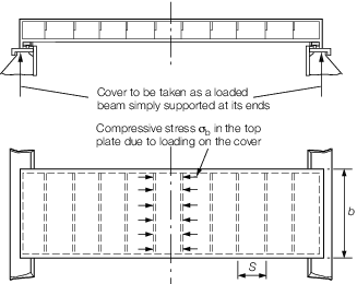
Figure 11.2.8 Cover with stiffening fitted normal to the axis of primary bending
|