
Section
17 Split hopper dredgers and barges
17.1 Symbols and definitions
17.1.1 The
symbols used in this Section are defined as follows:
|
H
|
= |
height
of spoil above base line, in metres |
|
H
s
|
= |
depth of hopper seal, in metres |
|
L
h
|
= |
length of hopper well, in metres |
|
M
H
|
= |
design horizontal bending moment in hopper side wall, in kN m. A
moment giving rise to tensile stress in the side shell is to be taken as
positive |
|
|
= |
4,9 (p (H – H
s)2 – 1,025
(T – H
s)2) kN/m
|
|
S
h
|
= |
span between the centres of hinges, in metres |
17.2 Hull bending strength
17.2.1 The
modulus of the cross-section of the vessel is to be not less than
that required by Pt 4, Ch 12, 2.3 Hull bending strength 2.3.1. In
addition, the combined stress σc, at any point on
the cross-section of one half hull, is not to exceed the permissible
combined stress σ given in Pt 3, Ch 4, 5.5 Permissible still water bending moments. The combined stress at any point on the cross-section
is to be determined from the following expression:
where
|
M
N
|
= |
± M
V cos φ ± M
H sin φ kN m |
|
M
p
|
= |
± M
H cos φ ± M
V sin φ kN m |
|
M
V
|
= |
± 0,5 (M
s + M
w) kN m |
where the still water bending moments hogging and sagging are
to be combined with the appropriate wave bending moment to give a
total moment, M
V, hogging (positive) and sagging
(negative)
M
w is defined in Pt 4, Ch 12, 1.5 Symbols 1.5.1.
|
M
H
|
= |
0,125PL
h(2S
h − L
h) ± M
L kN m |
|
M
L
|
= |
0,286 f
1
L
2
B kN m |
|
P
|
= |
4,9(ρ(H − H
s)2 − 1,025 (T
− H
s)2) kN m
|
Account is to be taken of the sign of individual
bending moment component in the determination of M
N, M
p, M
V and M
H
|
I
NN
|
= |
second moment of area of the section of one half hull for all
longitudinal continuous material above principal axis NN, in m4
|
|
I
PP
|
= |
second moment of area of the section of one half hull for all
longitudinal continuous material about principal axis PP, in m4
|
|
Z
p
|
= |
 in m3, the modulus of section to a point yP m,
from the principal axis PP in m3, the modulus of section to a point yP m,
from the principal axis PP
|
|
Z
N
|
= |
 in m3, the modulus of section to a point yN m,
from the principal axis NN in m3, the modulus of section to a point yN m,
from the principal axis NN
|
|
φ
|
= |
angle
of rotation of the principal axis NN with respect to the global horizontal
axis YY, in degrees |
See also
Figure 12.17.1 Split hulled vessels.
17.3 Separation arrangements
17.3.1 Hinges,
actuating and locking devices provided to facilitate separation of
the split hulls to discharge spoil are to be of efficient design and
of adequate strength and scantlings to ensure safe discharge operations.
Hydraulic rams or other actuating devices are to have sufficient power
to ensure controlled opening operations and to achieve closing of
the hulls in all anticipated weather conditions.
17.3.2 Locking
devices are to be of a suitable design and strength to ensure that
accidental separation of the hulls cannot occur due to ship motions
and vibrations.
17.3.3 Hinge
pin gudgeons are to be efficiently connected to the hull structure
by means of brackets or equivalent and effectively integrated with
local structure which is to be suitably reinforced. Suitable reinforcement
is to be fitted to local hull structure in way of anchorages for rams
and locking devices to ensure efficient transmission of loading from
these devices into the hull.
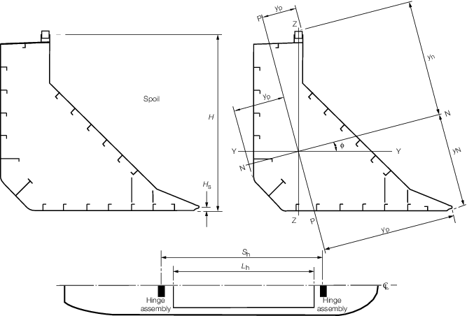
Figure 12.17.1 Split hulled vessels
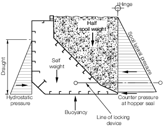
Figure 12.17.2 Split hopper dredger
17.3.4 The
forces acting on hinges, actuating mechanisms and locking devices
are to be determined by direct calculations based on the maximum combination
of loading which can be expected in any service condition. In general,
this will require the resolution of the static and dynamic systems
of force acting on the hulls taking due account of the relative locations
of hinges, actuating mechanisms and locking devices. Figure 12.17.2 Split hopper dredger illustrates a typical
arrangement of hinges and mechanisms together with associated static
loads. In general, one half of the load acting on one half hull may
be assumed to act on the forward hinge assembly and one half on the
after hinge assembly.
17.4 Hinge pins
17.4.1 The diameter of the hinge pins is to be determined using the maximum
resultant shear force acting on the pin cross-section in conjunction with an average
shear stress not exceeding  . .
In no case is the diameter of the hinge pin to be less than
that calculated from the following expression:
and L, B and D are defined in Pt 4, Ch 12, 1.5 Symbols 1.5.1.
17.4.2 Where
arrangements are such that hinge pins are subjected to significant
bending, the diameter of the pins will be specially considered.
|
| Copyright 2026 Clasifications Register Group Limited, International Maritime Organization, International Labour Organization or Maritime
and Coastguard Agency. All rights reserved. Clasifications Register Group Limited, its affiliates and subsidiaries and their respective
officers, employees or agents are, individually and collectively, referred to in this clause as 'Clasifications Register'. Clasifications
Register assumes no responsibility and shall not be liable to any person for any loss, damage or expense caused by reliance
on the information or advice in this document or howsoever provided, unless that person has signed a contract with the relevant
Clasifications Register entity for the provision of this information or advice and in that case any responsibility or liability is
exclusively on the terms and conditions set out in that contract.
|
 |
|