
Section
3 Longitudinal strength
3.1 General
3.1.2 The requirements of Pt 3, Ch 4, 8.3 Loading instrument
regarding loading instruments are not applicable to general cargo ships under 120 m with
the exception of ships with the notation Hatch Covers may be omitted in Hold (No(s)
...).
3.2 Fast cargo ships
3.2.1 The
hull section modulus for ships of length, L, between
120 m, and 170 m, and maximum service speed greater than 17,5 knots
in association with a bow shape factor, ψ, of more
than 0,15, is to comply with the requirements of this sub-Section.
3.2.2 The
bow shape factor is defined as:
where
|
a
0
|
= |
projection of upper deck at waterline (F.P.), in metres |
|
a
1
|
= |
projection of upper deck at waterline (0,1L from
F.P.), in metres
|
|
a
2
|
= |
projection of upper deck at waterline (0,2L from
F.P.), in metres
|
|
b
|
= |
projection
of upper deck at waterline (F.P. to bow line), in metres |
|
|
= |

|
See also
Figure 1.3.1 Derivation of bow shape factor.
3.2.3 For
longitudinal strength requirements, the Rule minimum hull midship
section modulus and the distribution of longitudinal material in the
forward half-length will be considered. In general, the following
requirements are to be complied with:
-
The vertical hull
midship section modulus, about the horizontal neutral axis, at deck
is to be not less than 331LkΣA
b cm3, or that required by Pt 3, Ch 4, 5 Hull bending strength, whichever is the greater. ΣA
b is
defined in Pt 4, Ch 1, 3.2 Fast cargo ships 3.2.2.
-
The horizontal
hull midship section modulus, about a vertical axis through the ship
centreline, is to be not less than 32,5 L
2
D cm3.
-
In the forward
half-length, the hull section modulus is not to be a lesser percentage
of the midship value than that shown in Table 1.3.1 Fast cargo ships.
-
Any load or ballast
condition resulting in a sagging still water bending moment, or a
hogging moment less than 80 per cent of the Rule value of still water
bending moment, will be specially considered with a view to minimising
the compressive stresses in the deck in waves.
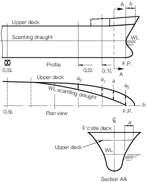
Figure 1.3.1 Derivation of bow shape factor
Table 1.3.1 Fast cargo ships
| Position
|
Percentage of midship vertical modulus(modulus about horizontal
axis)
|
Percentage of midship horizontal modulus(modulus about vertical
axis)
|
| Station
10 (mid-L
pp)
|
100
|
100
|
| 12
|
98
|
87
|
| 14
|
95
|
62
|
| 16
|
81
|
38
|
| 18
|
44
|
17
|
| 20
(F.P.)
|
0
|
0
|
Note
1. Intermediate values to be obtained by
interpolation.
|
3.2.4 For
local strength, in general the following requirements are to be complied
with:
-
Longitudinal deck
stiffening is to be carried forward to the fore peak bulkhead or as
far forward as practical. Where a long forecastle is fitted, the buckling
strength of the proposed structure will be specially considered.
-
Substantial web
frames in way of deck transverses are to be fitted in the forward
half-length. Scantlings of webs and frames are to be based on actual
lengths, not 'tween deck heights, and collars are to be fitted at
ends of members in way of high shear.
-
Scantlings of
bottom structure in forward part are to be specially considered.
-
Deck and side
shell panels forward of 0,5L from F.P. are to be examined
to establish the critical buckling stress from the following formula:
- where
|
s
|
= |
length
of shorter edge, in mm |
|
t
|
= |
thickness
of plating, in mm |
|
E
|
= |
Young's modulus, in N/mm2
|
|
K
c
|
= |
a factor depending on aspect ratio and boundary restraint |
|
|
= |
4 for longitudinally
stiffened plating or as shown in Figure 1.3.2 Plate factor, K
c
for transversely stiffened plating
|
|
ν |
= |
Poisson's ratio
(0,3 for steel and aluminium alloy). |
Where the buckling stresses, as evaluated, exceed 50 per cent
of yield stress, the actual critical buckling stress is given by:
- where
|
σac
|
= |
corrected critical buckling stress, in N/mm2
|
|
σo
|
= |
yield stress, in N/mm2
|
The critical buckling stress from the above formulae must be not less
than 176,6 N/mm2 within 0,4L amidships, nor less than 147,2
N/mm2 for the deck forward of this, nor less than 117,7
N/mm2 for the side shell between the first and second deck forward
of 0,5L from F.P. For higher tensile steel plating, the above permissible
stresses are to be divided by k.
-
In order to obtain
the necessary critical buckling strength, either of the following
is to be applied:
-
plate thickness
to be increased, or
-
panel aspect
ratio to be altered by the fitting of additional panel stiffening.
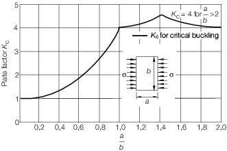
Figure 1.3.2 Plate factor, K
c
|
| Copyright 2022 Clasifications Register Group Limited, International Maritime Organization, International Labour Organization or Maritime
and Coastguard Agency. All rights reserved. Clasifications Register Group Limited, its affiliates and subsidiaries and their respective
officers, employees or agents are, individually and collectively, referred to in this clause as 'Clasifications Register'. Clasifications
Register assumes no responsibility and shall not be liable to any person for any loss, damage or expense caused by reliance
on the information or advice in this document or howsoever provided, unless that person has signed a contract with the relevant
Clasifications Register entity for the provision of this information or advice and in that case any responsibility or liability is
exclusively on the terms and conditions set out in that contract.
|
 |
|