
Section
8 Bow doors and inner doors
8.1 Symbols
8.1.1 The
symbols used in this Section are defined as follows:
|
h
|
= |
height
of the door, in metres, between the levels of the bottom of the door
and the upper deck or between the bottom of the door and the top of
the door, whichever is the lesser, see
Figure 2.8.2 Definition of α and β
|
|
k
|
= |
material
factor (see
Pt 3, Ch 2, 1.2 Steel),
but is not to be taken less than 0,72 unless demonstrated otherwise
by a direct strength analysis with regard to relevant modes of failure
|
|
w
|
= |
width
of bow door at half height, in metres |
|
A
z
|
= |
area, in m2, of the horizontal projection of the
bow door, between the bottom of the door and the top of the upper
deck bulwark, or between the bottom of the door and the top of the
door, including the bulwark, where it is part of the door,whichever
is the lesser, see
Figure 2.8.1 Bow door (upward hinging). Where the flare angle of the bulwark is at least 15
degrees less than the flare angle of the adjacent shell plating, the
height from the bottom of the door may be measured to the upper deck
or to the top of the door, whichever is the lesser
|
|
A
s
|
= |
area of stiffener web, in cm2
|
|
A
x
|
= |
area, in m2, of the transverse vertical projection
of the bow door, between the bottom of the door and the top of the
door or between the bottom of the door and the upper deck bulwark,
or between the bottom of the door and the top of the door, including
the bulwark, where it is part of the door, whichever is the lesser, see
Figure 2.8.1 Bow door (upward hinging) Where
the flare angle of the bulwark is at least 15 degrees less than the
flare angle of the adjacent shell plating, the height from the bottom
of the door may be measured to the upper deck or to the top of the
door, whichever is lesser. In determining the height from the bottom
of the door to the upper deck or to the top of the door, the bulwark
is to be excluded
|
|
A
y
|
= |
area, in m2, of the longitudinal vertical projection
of the bow door, between the bottom of the door and the top of the
upper deck bulwark, or between the bottom of the door and the top
of the door, including the bulwark, where it is part of the door,
whichever is the lesser, see
Figure 2.8.1 Bow door (upward hinging) Where the flare angle
of the bulwark is at least 15 degrees less than the flare angle of
the adjacent shell plating, the height from the bottom of the door
may be measured to the upper deck or to the top of the door, whichever
is the lesser
|
|
W
|
= |
weight
of bow visor, in tonnes |
|
q
|
= |
distance,
in metres, from the centroid of the hydrostatic head profile, to the
top of the cargo space |
|
C
H
|
= |
0,0125L where L < 80 m
|
| = |
1,0 where L ≥ 80 m
|
|
L
|
= |
length
of ship, but need not be taken greater than 200 m |
|
λ |
= |
coefficient
depending on the area where the ship is intended to be operated |
| = |
1,0 for sea-going ships |
| = |
0,8 for ships operated in coastal waters |
| = |
0,5 for ships operated in sheltered waters |
|
σ |
= |
bending stress, in N/mm2
|
|
σe
|
= |
equivalent stress, in N/mm2
|
|
|
= |

|
|
σy
|
= |
yield stress of the bearing material, in N/mm2
|
|
τ
|
= |
shear stress, in N/mm2. |
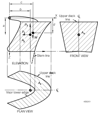
Figure 2.8.1 Bow door (upward hinging)
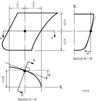
Figure 2.8.2 Definition of α and β
8.2 General
8.2.1 Bow
doors are defined by the following types:
-
Visor doors opened
by rotating upwards and outwards about a horizontal axis through two
or more hinges located near the top of the door and connected to the
primary structure of the door by longitudinally arranged lifting arms.
-
Side-opening doors
opened either by rotating outwards about a vertical axis through two
or more hinges located near the outbound edges or by horizontal translation
by means of linking arms arranged with pivoted attachments to the
door and the ship. It is expected that side-opening bow doors will
be arranged in pairs.
Other bow door types will be specially considered.
8.2.2 Bow
doors are to be situated above the freeboard deck. A watertight recess
in the freeboard deck located forward of the collision bulkhead and
above the deepest waterline, fitted for arrangement of ramps or other
related mechanical devices, may be regarded as a part of the freeboard
deck for the purpose of this requirement.
8.2.3 Where
bow doors lead to a complete or long forward enclosed superstructure,
or to a long non-enclosed superstructure which is fitted to attain
minimum bow height equivalence, an inner door is to be fitted. The
inner door is to be part of the collision bulkhead. Where a sloping
vehicle ramp forming the collision bulkhead above the freeboard deck
is arranged, the inner door may be omitted if the ramp is weathertight
over its complete length and fulfils the requirements of Pt 3, Ch 3 Structural Design concerning the position of
the collision bulkhead.
8.2.4 Bow
doors are to be fitted with arrangement for ensuring weathertight
sealing, such as gaskets, and to give effective protection to inner
doors.
8.2.5 Inner
doors forming part of the collision bulkhead are to be watertight
over the full height of the cargo space and arranged with fixed sealing
supports on the aft side of the doors.
8.2.6 Bow
doors and inner doors are to be arranged so as to preclude the possibility
of the bow door causing structural damage to the inner door or to
the collision bulkhead in the case of damage to or detachment of the
bow door. If this is not possible, a second separate inner weathertight
door, complying with Pt 4, Ch 2, 8.2 General 8.2.5,
is to be installed.
8.2.7 The
requirements for inner doors are based on the assumption that vehicles
and cargo are effectively lashed and secured against movement from
the stowed position.
8.2.8 For
ships complying with the requirements of this Section, the securing,
supporting and locking devices are defined as follows:
-
A securing device
is used to keep the door closed by preventing it from rotating about
its hinges.
-
A supporting device
is used to transmit external and internal loads from the door to a
securing device and from the securing device to the ship's structure,
or a device other than a securing device, such as a hinge, stopper
or other fixed device, that transmits loads from the door to the ship's
structure.
-
A locking device
locks a securing device in the closed position.
8.3 Scantlings
8.3.2 For
bow doors, including bulwark, of unusual form or proportions, the
areas and angles used for the determination of design values of external
forces are to be specially considered.
8.3.3 Bow
doors of the visor or hinged opening type are to be adequately stiffened,
and means are to be provided to prevent lateral or vertical movement
of the doors when closed. Care is to be taken to ensure that adequate
strength is provided in the connections of the hinge or linking arms
to the door structure and to the ship structure.
8.3.4 The
thickness of the bow door plating is not to be less than the side
shell plating calculated with the door stiffener spacing, and in no
case to be less than the minimum shell plate end thickness or forecastle
side thickness as appropriate.
8.3.5 The
section modulus of horizontal or vertical stiffeners is not to be
less than required for end framing. Consideration is to be given,
where necessary, to differences in fixity between ship frames and
bow door stiffeners.
8.3.6 The
stiffener webs are to have a net sectional area not less than:
τ is to be taken as 
8.3.7 Bow
door secondary stiffeners are to be supported by primary members constituting
the main stiffening elements of the door.
8.3.8 The
scantlings of such primary members are to be based on direct strength
calculations. Normally, formulae for simple beam theory may be applied
to determine the bending stress. Members are to be considered to have
simply supported end connections. The design load, P
e,
is the uniformly distributed external sea pressure. The formulae for P
e given in Pt 4, Ch 2, 8.6 Design of securing and supporting devices 8.6.1,
may be used with α and β defined as:
|
α |
= |
flare angle,
in degrees, generally to be measured normal to the shell between the
vertical axis and the vertical tangent to the outer shell of the door
measured at the point on the bow door, one half of the projected length
( /2) aft of the stern line on the plane at the half height
of the door (h/2) (see
Figure 2.8.2 Definition of α and β) /2) aft of the stern line on the plane at the half height
of the door (h/2) (see
Figure 2.8.2 Definition of α and β)
|
|
β |
= |
entry angle,
in degrees, generally to be measured on the outer shell of the door
between the longitudinal axis and the waterplane tangent measured
at the point on the bow door, one half of the projected length ( /2) aft of the stem line on the plane at the half height
of the door (h/2) (see
Figure 2.8.2 Definition of α and β) /2) aft of the stem line on the plane at the half height
of the door (h/2) (see
Figure 2.8.2 Definition of α and β)
|
The permissible stresses are as follows:
8.3.9 The
webs of primary members are to be adequately stiffened, preferably
in a direction perpendicular to the shell plating.
8.3.10 The
primary members of the bow doors and hull structure in way are to
have sufficient stiffness to ensure the integrity of the boundary
support of the doors.
8.3.11 All
load transmitting elements in the design load path, from door through
securing arrangements and supporting devices into the ship structure,
including welded connections, are to be to the same strength standard.
These elements include pins, supporting brackets and back-up brackets.
Where cut-outs are made in the supporting structure, the strength
and stiffness will be specially considered.
8.3.12 For
bow doors and inner doors, the distribution of forces acting on the
securing devices and the supporting devices is to be supported by
direct calculations taking into account the flexibility of the structure
and the actual position and stiffness of the supports.
8.3.13 The
buckling strength of primary members is to be specially considered.
8.4 Vehicle ramps
8.5 Arrangements for the closing, securing and supporting of doors
8.5.1 Bow
doors are to be fitted with adequate means of closing, securing and
supporting so as to be commensurate with the strength and stiffness
of the surrounding structure. The hull supporting structure in way
of the bow doors is to be suitable for the same design loads and design
stresses as the securing and supporting devices. Where packing is
required, the packing material is to be of a comparatively soft type,
and the supporting forces are to be carried by the steel structure
only. Maximum design clearance between securing and supporting devices
is not to exceed 3 mm.
8.5.2 Securing
devices are to be simple to operate and easily accessible. They are
to be of a design approved by LR for the intended purpose.
8.5.3 Securing
devices are to be equipped with positive locking arrangements. Arrangements
are to be such that the devices are retained in the closed position
within design limits of inclination, vibration and other motion-induced
loads and in the event of loss of any actuating power supply.
8.5.4 Systems
for door opening/closing and securing/locking are to be interlocked
in such a way that they can only operate in a proper sequence. Hydraulic
systems are to comply with Pt 5, Ch 14, 9 Hydraulic systems.
8.5.5 Means
are to be provided to enable the bow doors to be mechanically fixed
in the open position taking into account the self-weight of the door
and a minimum wind pressure of 1,5 kN/m2 (0,153 tonne-f/m2) acting on the maximum projected area in the open position.
8.5.6 The
spacing for side and top cleats should not exceed 2,5 m and there
should be cleats positioned as close to the corners as practicable.
Alternative arrangements for ensuring weathertight sealing will be
specially considered.
8.6 Design of securing and supporting devices
8.6.1 The
external design forces for securing devices, supporting devices and
surrounding structure are to be taken not less than P,
taking the direction of the pressure into account:
where
|
p
e
|
= |
external sea pressure, not to be taken less than: |
-
For bow doors:
|
p
e
|
= |
0,8 (0,15V + 0,6 )2 kN/m2 )2 kN/m2
|
or
|
p
e
|
= |
2,75λ C
H (0,22 + 0,15 tan α)
(0,4V sin β + 0,6 )2 kN/m2 )2 kN/m2
|
whichever is the greater.
-
For inner doors:
or
whichever is the greater
The symbols are as defined in Pt 4, Ch 2, 8.1 Symbols 8.1.1.
8.6.2 The inner door internal design pressure, considered for the scantlings of
securing devices, is not to be less than 25 kN/m2 .
8.6.3 For
visor doors, the pivot arrangement is to be such that the visor is
self-closing under external loads. The closing moment, M
c, is to be taken as:
but is not to be less than:
8.6.4 For
visor doors, two securing devices are to be provided at the lower
part of the door, each capable of providing the full reaction force
required to prevent opening of the door within the permissible stresses
given in Pt 4, Ch 2, 8.6 Design of securing and supporting devices 8.6.7. The opening
moment M
o, to be balanced by this reaction
force, is to be taken as not less than:
8.6.6 For
side-opening doors, securing devices are to be provided such that
in the event of a failure of any single securing device the remainder
are capable of providing the full reaction force required to prevent
the opening of the door. The permissible stresses given in Pt 4, Ch 2, 8.6 Design of securing and supporting devices 8.6.7 are not to be exceeded. The
opening moment about the hinges to be balanced by this reaction force
is not to be less than that calculated when the following loads are
applied:
-
An internal pressure of 5 kN/m2.
-
A force of 10W kN acting forward at the centroid of mass.
8.6.7 Securing
devices and supporting devices are to be designed to withstand the
forces given above using the following permissible stresses:
8.6.8 The
arrangement of securing and supporting devices is to be such that
threaded bolts are not to carry support forces. The maximum tensile
stress in way of threads of bolts, not carrying support forces, is
not to exceed:
8.6.9 For
steel to steel bearings in securing and supporting devices, the nominal
bearing pressure is not to exceed 0,8σy. For other
bearing materials, the permissible bearing pressure is to be determined
according to the manufacturer’s specification. The nominal bearing
pressure is to be calculated by dividing the design force by the projected
bearing area.
8.6.10 The
reaction forces to be applied to the effective securing and supporting
devices are to be determined from the combination of external loads
defined in Table 2.8.1 Combination of external
loads.
Table 2.8.1 Combination of external
loads
| Bow door type
|
Combination of external loads
|
Case
1
(Head seas)
|
Case
2
(Quartering seas)
|
| Visor doors, see Notes 1 and 2
|
P
x and P
z
see Note 3
|
0,7P
y acting on each side separately, together with 0,7P
x and 0,7P
z
|
Side
opening,
see Notes 1 and 2
|
P
x, P
y and P
z acting on both doors, see Note 3
|
0,7P
x and 0,7P
z acting on both doors and 0,7P
y acting on each door separately
|
Note
2. The self-weight of the door is to be
included in the combination of external loads.
|
8.6.11 The
distribution of the reaction forces acting on the securing and supporting
devices is to be supported by direct calculations taking into account
the flexibility of the hull structure and the actual position and
stiffness of the supports. Small and/or flexible devices, such as
cleats, intended to provide load compression of the packing material
are not to be included in these calculations.
8.6.12 The hinge or linking arms of a bow door and its supports are to be designed
for the static and dynamic opening forces. A minimum wind pressure of 1,5
kN/m2, acting on the transverse projected area of the door is to be taken
into account.
8.6.13 For
side-opening doors, supporting devices are to be provided in way of
girder ends at the closing of the two doors to prevent one side shifting
towards the other under the effect of asymmetrical pressure. A typical
arrangement is shown in Figure 2.8.3 Typical supporting device between doors.
8.6.14 Inner
doors are to be gasketed and weathertight.
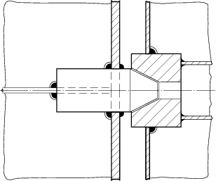
Figure 2.8.3 Typical supporting device between doors
8.6.15 Only
the active supporting and securing devices having an effective stiffness
in the relevant direction are to be included and considered to calculate
the reaction forces acting on the devices.
8.7 Operating and Maintenance Manual
8.7.1 An Operating
and Maintenance Manual for the bow doors and inner doors is to be
provided on board and is to contain the following information:
-
main particulars
and design drawings,
- special safety precautions;
- details of vessel;
- equipment and design loading for ramps;
- key plan of equipment for doors and ramps;
- manufacturers' recommended testing for equipment; and
- a description of the equipment for:
|
|
bow doors;
|
|
|
inner bow doors;
|
|
|
bow ramp/doors;
|
|
|
side doors;
|
|
|
stern doors;
|
|
|
central power pack;
|
|
|
bridge panel;
|
|
|
ramps leading down from the main deck;
|
|
|
engine control room panel.
|
-
service conditions:
- limiting heel and trim of the ship for loading/unloading;
- limiting heel and trim for door operations;
- operating instructions for doors and ramps; and
- emergency operating instructions for doors and ramps.
-
maintenance:
- schedule and extent of maintenance;
- troubleshooting and acceptable clearances; and
- manufacturers' maintenance procedures.
-
register of inspections,
including inspection of locking, securing and supporting devices,
repairs and renewals.
This Manual is to be submitted for approval, and is to contain
a note recommending that recorded inspections of the door supporting
and securing devices be carried out by the ship’s staff at monthly
intervals or following incidents that could result in damage, including
heavy weather or contact in the region of the doors. Any damages recorded
during such inspections are to be reported to LR.
8.7.2 Documented
operating procedures for closing and securing the bow doors and inner
doors are to be kept on board and posted at an appropriate place.
|