
Section
10 Hull strengthening requirements for navigation in multi-year
ice conditions – Ice Classes PC1, PC2, PC3, PC4, PC5, PC6, PC7
and Icebreaker
10.1 Definitions
10.1.1 The length LUI is the distance, in m, measured horizontally from
the fore side of the stem at the intersection with the upper ice waterline (UIWL) to
the after side of the rudder post, or the centre of the rudder stock if there is no
rudder post. LUI is not to be less than 96 per cent, and need not
be greater than 97 per cent, of the extreme length of the upper ice waterline (UIWL)
measured horizontally from the fore side of the stem. In ships with unusual stern
and bow arrangement the length LUI will be specially
considered.
10.1.2 The ship displacement ΔUI is the displacement, in kilo tonnes, of the ship
corresponding to the upper ice waterline (UIWL). Where multiple waterlines are used
for determining the UIWL, the displacement is to be determined from the waterline
corresponding to the greatest displacement.
10.2 Hull areas
10.2.1 The hull of all polar class ships is divided into areas reflecting the
magnitude of the loads that are expected to act upon them, see
Figure 2.10.1 Extent of hull areas. In the longitudinal direction,
there are four regions:
-
bow, (B);
-
bow intermediate, (B
i);
-
midbody, (M), and
-
stern (S).
The bow intermediate, midbody and stern regions are further divided in the
vertical direction into three regions:
-
bottom, (b)
-
lower, (l) and
-
icebelt (i).
10.2.3 In addition to Figure 2.10.1 Extent of hull areas, at no time is the boundary
between the bow and bow intermediate regions to be forward of the intersection point of
the line of the stem and the ship baseline.
10.2.4 In addition to Figure 2.10.1 Extent of hull areas, the aft boundary of
the bow region need not be more than 0,45LUI aft of the fore side of
the stem at the intersection with the upper ice waterline (UIWL)
10.2.5 The forward boundary of the stern region is to be at least a distance
Z from the aft end of LUI, where Z is 0,7b or
0,15L UI whichever is greater. b is the distance from the
aft end of LUI to the maximum half breadth at the UIWL and
LUI is defined in Pt 8, Ch 2, 10.1 Definitions.
10.2.6 The boundary between the bottom and lower regions is to be taken at the
point where the tangent to the shell is inclined 7° from horizontal.
10.2.8 In addition to Figure 2.10.1 Extent of hull areas if the ship is assigned the
additional notation Icebreaker the forward boundary of the stern region is to be
at least 0,04L forward of the section where the parallel ship side at the upper
ice waterline (UIWL) ends.
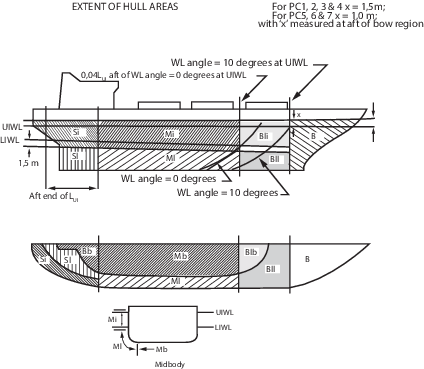
Figure 2.10.1 Extent of hull areas
10.3 Design ice loads – General
10.3.1 For ships of all Polar Classes, a glancing impact on the bow is the design
scenario for determining the scantlings required to resist ice loads.
10.3.2 The design ice load is characterised by an average pressure, P
a, uniformly distributed over a rectangular load patch of height, b,
and width, w.
10.3.3 Within the bow area of all polar classes, and within the bow intermediate
icebelt area of polar classes PC6 and PC7, the ice load parameters are
functions of the actual bow shape. To determine the ice load parameters,
Pa
, b and w, it is required to calculate the following ice load
characteristics for sub-regions of the bow area; shape coefficient, f
ai, total glancing impact force, F
i, line load, Q
i, and pressure, P
i.
10.3.4 For polar classes PC6 and PC7 the ice load parameters,
Pa, b and w, determined as a function of the bow
shape in bow region, B, are also to be applied to bow intermediate icebelt
region, BIi.
10.3.5 In other ice-strengthened areas, the ice load parameters, Pa
, b
NB and w
NB, are determined independently of the hull shape and based on a fixed load
patch aspect ratio, AR = 3.6.
10.3.10 Ship structures that are not directly subjected to ice loads may still
experience inertial loads of stowed cargo and equipment resulting from ship/ice
interaction. These inertial loads are to be considered in the design of these
structures.
10.4 Glancing impact load characteristics
10.4.1 The parameters defining the glancing impact load characteristics are
reflected in the class factors listed in Table 2.10.1 Class factors for icebreaking bow
forms and Table 2.10.2 Class factors for vertical side
bow forms.
Table 2.10.1 Class factors for icebreaking bow
forms
| Polar Class
|
Crushing failure class
factor
|
Flexural failure class
factor
|
Load patch dimensions class
factor
|
Displacement class factor
|
Longitudinal strength class
factor
|
|
C
C
|
C
F
|
C
D
|
C
DI
|
C
L
|
|
PC1
|
17,69
|
68,60
|
2,01
|
250
|
7,46
|
|
PC2
|
9,89
|
46,80
|
1,75
|
210
|
5,46
|
|
PC3
|
6,06
|
21,17
|
1,53
|
180
|
4,17
|
|
PC4
|
4,50
|
13,48
|
1,42
|
130
|
3,15
|
|
PC5
|
3,10
|
9,00
|
1,31
|
70
|
2,50
|
|
PC6
|
2,40
|
5,49
|
1,17
|
40
|
2,37
|
|
PC7
|
1,80
|
4,06
|
1,11
|
22
|
1,81
|
Table 2.10.2 Class factors for vertical side
bow forms
| Polar Class
|
Crushing failure class factor
|
Line load class factor
|
Pressure class factor
|
| CCV
|
CQV
|
CPV
|
| PC6
|
3,43
|
2,82
|
0,65
|
| PC7
|
2,60
|
2,33
|
0,65
|
10.5 Bow area
10.5.1 In
the bow area, the force, F, line load, Q,
pressure, P, and load patch aspect ratio, AR,
associated with the glancing impact load scenario are functions of
the hull angles measured at the upper ice waterline, UIWL. The influence
of the hull angles is captured through calculation of a bow shape
coefficient, fa. The hull angles are defined in Figure 2.10.2 Definition of hull angles.
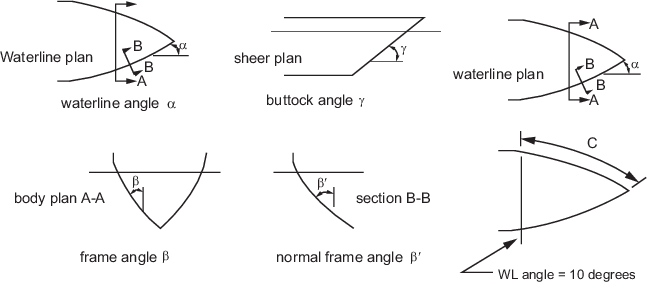
where
|
β' |
= |
normal frame angle at upper ice waterline, in degrees |
|
α |
= |
normal frame angle at upper ice waterline, in degrees |
|
γ |
= |
buttock angle at upper ice waterline (angle of buttock line measured from
horizontal), in degrees |
|
tan(β) |
= |
 |
|
tan(β') |
= |
tan (β) cos(α) |
|
C |
= |
waterline length of the bow region
|
Figure 2.10.2 Definition of hull angles
10.5.2 The waterline length of the bow region, C, is generally to be divided
along the UIWL into four sub-regions of equal length. The force, F, line load,
Q, pressure, P, and load patch aspect ratio, AR, are to be
calculated with respect to the mid - length position of each sub-region (each maximum of
F, Q and P is to be used in the calculation of the ice load
parameters Pa
, b and w).
10.5.3 The bow area load characteristics for icebreaking bow forms, as defined in
Pt 8, Ch 2, 10.3 Design ice loads – General 10.3.6, are
determined as follows:
-
The shape coefficient, fai
, is to be taken as:
- fa
i,2
- fa
i,3 whichever is the lesser
where
|
fa
i,1
|
= |

|
|
fa
i,2
|
= |

|
|
i
|
= |
sub-region
considered |
|
x
|
= |
distance from the fore side of the stem at the intersection
with the upper ice waterline (UIWL) station under consideration, in
metres |
-
Force, Fi
:
where
|
i
|
= |
sub-region
considered |
|
fai
|
= |
shape coefficient of sub-region, i
|
-
Load patch aspect
ratio, ARi
:
where
|
i
|
= |
sub-region
considered |
|
β'i
|
= |
normal
frame angle of sub-region i, in degrees
|
-
Line load, Q
i:
|
Q
i
|
= |
 MN/m MN/m |
where
|
i
|
= |
sub-region
considered |
|
F
i
|
= |
force of sub-region i, in MN
|
|
AR
i
|
= |
load patch aspect ratio of sub-region i
|
-
Pressure, P
i:
|
P
i
|
= |
F
i
0,22
C
D
2
AR
i
0,3 MPa
|
10.5.4 The bow area load characteristics for bow forms with vertical sides, as defined in Pt 8, Ch 2, 10.3 Design ice loads – General 10.3.7, are
determined as follows:
- The shape coefficient, fai, is to be taken as:
- Force, Fi:
- Line load, Qi:
- Pressure, Pi:
10.6 Hull areas other than the bow
10.6.1 In the hull areas other than the bow, the force, FNB, and
line load, QNB, used in the determination of the load patch
dimensions, bNB, wNB, and design pressure, P
a, are determined as follows:
-
Force, F
NB:
where
|
ΔF
|
= |
ship displacement factor |
|
|
= |
CDI
0,64 + 0,10 (ΔDI – CDI) if
ΔUI ≤ CDI
|
-
Line Load, Q
NB:
|
Q
NB
|
= |
0,639F
NB
0,61
C
D MN/m
|
where
10.7 Design load patch
10.7.1 In
the bow area, and the bow Intermediate Icebelt area for ships with
class notation PC6 and PC7, the design load
patch has dimensions of width, w
B, and height, b
B, defined as follows:
|
w
B
|
= |
 m m
|
|
b
B
|
= |
 m m
|
where
|
F
B
|
= |
maximum F
i in the bow area, in MN
|
|
Q
B
|
= |
maximum Q
i in the bow area, in MN/m
|
|
P
B
|
= |
maximum P
i in the bow area, in MPa.
|
10.7.2 In
hull areas other than those covered by Pt 8, Ch 2, 10.7 Design load patch 10.7.1, the design load patch has dimensions of width, w
NB, and height, b
NB, defined as follows:
|
w
NB
|
= |
 m m |
|
b
NB
|
= |
 m m |
where
10.8 Pressure within the design load patch
10.8.1 The
average pressure, P
a, within a design load
patch is determined as follows:
|
P
a
|
= |
 MPa MPa
|
where
|
F
|
= |
F
B or F
NB as appropriate for the hull
area under consideration, in MN
|
|
b
|
= |
b
B or b
NB as appropriate for the hull
area under consideration, in metres
|
|
w
|
= |
w
B or w
NB as appropriate for the hull
area under consideration, in metres.
|
10.8.2 Areas of higher, concentrated pressure exist within the load patch. In
general, smaller areas have higher local pressures. Accordingly, the peak pressure
factors listed in Table 2.10.3 Peak pressure factors are used to account for the pressure
concentration on localised structural members.
Table 2.10.3 Peak pressure factors
| Structural member
|
Peak
pressure factor, K
i
|
| Plating
|
Transversely framed
|
K
p = (1,8 – s) ≥ 1,2
|
|
|
Longitudinally framed
|
K
p = (2,2 – 1,2s) ≥ 1,5
|
| Frames in transverse framing
systems
|
With load distributing stringers
see Note 1
|
K
t = (1,6 – s) ≥ 1,0
|
|
|
With no load distributing stringers
see Note 1
|
K
t = (1,8 – s) ≥ 1,2
|
| Frames in
bottom structures
|
Ks = 1
|
| Load carrying stringers see Note 2
|
K
s = 1
|
if S
w ≥ 0,5w
|
Side
longitudinals
Web frames
|
K
s = 2 – 
|
if S
w < 0,5w
|
| Symbols
|
|
s
|
= |
frame or longitudinal spacing, in metres |
|
|
S
w
|
= |
web frame spacing, in metres |
|
|
w
|
= |
ice load patch width, in metres |
|
|
Note 1. Load distributing stringers are intercostal. Load distributing
stringer web height hlds is to be at least 80 per cent
of the adjacent main frame web height (hlds ≥
0,8h).
|
10.9 Hull area factors
10.9.1 Associated
with each hull area is an area factor that reflects the relative magnitude
of the load expected in that area. The area factor, AF,
for each hull area is listed in Table 2.10.4 Hull area factors (AF) .
10.9.2 In
the event that a structural member spans across the boundary of a
hull area, the largest hull area factor is to be used in the scantling
determination of the member.
10.9.3 Due to their increased manoeuvrability, ships having propulsion arrangements
with azimuth thruster(s) or podded propellers are to have specially considered stern
icebelt, Si, and stern lower, Sl, hull area factors.
See the Rules for the Classification of Stern First Ice Class Ships, July 2022.
Table 2.10.4 Hull area factors (AF)
| Hull
area
|
Area
|
Polar Class
|
|
PC1
|
PC2
|
PC3
|
PC4
|
PC5
|
PC6
|
PC7
|
| Bow (B)
|
All
|
B
|
1,00
|
1,00
|
1,00
|
1,00
|
1,00
|
1,00
|
1,00
|
| Icebelt
|
BI
i
|
0,90
|
0,85
|
0,85
|
0,80
|
0,80
|
1,00
|
1,00
|
|
|
|
|
|
|
see Note 1
|
see Note 1
|
| Bow
intermediate (BI)
|
Lower
|
BI
l
|
0,70
|
0,65
|
0,65
|
0,60
|
0,55
|
0,55
|
0,50
|
| Bottom
|
BI
b
|
0,55
|
0,50
|
0,45
|
0,40
|
0,35
|
0,30
|
0,25
|
| Midbody (M)
|
Icebelt
|
M
i
|
0,70
|
0,65
|
0,55
|
0,55
|
0,50
|
0,45
|
0,45
|
| Lower
|
M
l
|
0,50
|
0,45
|
0,40
|
0,35
|
0,30
|
0,25
|
0,25
|
| Bottom
|
M
b
|
0,30
|
0,30
|
0,25
|
see Note 2
|
see Note 2
|
see Note 2
|
see Note 2
|
| Stern
(S)
|
Icebelt
|
S
i
|
0,75
|
0,70
|
0,65
|
0,60
|
0,50
|
0,40
|
0,35
|
| Lower
|
S
l
|
0,45
|
0,40
|
0,35
|
0,30
|
0,25
|
0,25
|
0,25
|
| Bottom
|
S
b
|
0,35
|
0,30
|
0,30
|
0,25
|
0,15
|
see Note 2
|
see Note 2
|
Note
2. Indicates that strengthening for ice
loads is not necessary.
|
10.9.4 Area
factors to be applied to ships assigned the notation Icebreaker are
given in Table 2.10.5 Hull area factors (AF) for
icebreaker.
Table 2.10.5 Hull area factors (AF) for
icebreaker
|
|
B
|
BIi
|
BIl
|
BIb
|
Mi
|
Ml
|
Mb
|
Si
|
Sl
|
Sb
|
|
PC1
|
1
|
0,90
|
0,70
|
0,55
|
0,70
|
0,50
|
0,30
|
0,94
|
0,56
|
0,35
|
|
PC2
|
1
|
0,85
|
0,65
|
0,50
|
0,65
|
0,45
|
0,30
|
0,88
|
0,50
|
0,30
|
|
PC3
|
1
|
0,85
|
0,65
|
0,45
|
0,55
|
0,40
|
0,25
|
0,81
|
0,44
|
0,30
|
|
PC4
|
1
|
0,85
|
0,65
|
0,45
|
0,55
|
0,40
|
0,25
|
0,81
|
0,44
|
0,30
|
|
PC5
|
1
|
0,85
|
0,65
|
0,45
|
0,55
|
0,40
|
0,25
|
0,81
|
0,44
|
0,30
|
|
PC6
|
1
|
1
|
0,65
|
0,45
|
0,55
|
0,40
|
0,25
|
0,81
|
0,44
|
0,30
|
|
PC7
|
1
|
1
|
0,65
|
0,45
|
0,55
|
0,40
|
0,25
|
0,81
|
0,44
|
0,30
|
10.10 Shell plate requirements
10.10.1 The
required minimum shell plate thickness, t, is given by:
where
10.10.2 The thickness of shell plating required to resist the design ice load,
t
net, depends on the orientation of the framing. The plating net thickness is
given by Table 2.10.6 Shell plate thickness.
Table 2.10.6 Shell plate thickness
| Transversely framed plating
see Note 1
|
Obliquely framed plating
|
Longitudinally framed plating
|
| Ω ≥ 70°
|
70° > Ω >
20°
|
Ω ≤
20°
|
|
b ≥ s
|
b < s
|

|
linear interpolation
|

|

|
| Symbols
|
| where
|
|
s
|
= |
transverse frame spacing in transversely-framed ships
or longitudinal frame spacing in longitudinally-framed ships,
measured along the girth, in metres |
|
|
|
|
|
|
|
|
σ
y
|
= |
minimum upper yield stress of the material, in
N/mm2
|
|
|
b
|
= |
height of design load patch, in m, where b ≤
I –  in the case of determination of the net
thickness for transversely framed plating in the case of determination of the net
thickness for transversely framed plating |
|
|
l |
= |
distance between frame supports, i.e. equal to the
frame span as given in Pt 8, Ch 2, 10.11 Framing – General 10.11.5, but not reduced for any
fitted end brackets, in metres. When a load-distributing stringer
is fitted, the length, l, need not be taken larger than the
distance from the stringer to the most distant frame support. |
|
|
Note 1. Includes plating in hull areas BIb,
Mb and Sb regardless of actual
frame orientation.
|

Figure 2.10.3 Shell framing angle Ω
10.11 Framing – General
10.11.2 The term ‘framing member’ refers to transverse and longitudinal local
frames, load-carrying stringers and web frames in the areas of the hull exposed to ice
pressure, see
Figure 2.10.1 Extent of hull areas. Where load-distributing stringers
have been fitted, the arrangement and scantlings of these are to be suitably designed.
10.11.3 The
strength of a framing member is dependent upon the fixity that is
provided at its supports. Fixity can be assumed where framing members
are either continuous through the support or attached to a supporting
section with a connection bracket. In other cases, simple support
is to be assumed unless the connection can be demonstrated to provide
significant rotational restraint. Fixity is to be ensured at the support
of any framing which terminates within an ice-strengthened area.
10.11.4 The
details of framing member intersection with other framing members,
including plated structures, as well as the details for securing the
ends of framing members at supporting sections, are to be in accordance
with Pt 3, Ch 10 Welding and Structural Details.
10.11.5 The effective span of a framing member is to be determined on the basis of
its moulded length. If brackets are fitted, the effective span may be reduced in
accordance with Pt 3, Ch 3 Structural Design.
10.11.6 When
calculating the section modulus and shear area of a framing member,
the net thicknesses of the web, flange (if fitted) and attached shell
plating are to be used. The shear area of a framing member may include
that material contained over the full depth of the member, i.e. web
area including portion of flange, if fitted, but excluding attached
shell plating.
10.11.7 The actual net effective shear area, A
w, of a transverse or longitudinal local frame is given by:
where
|
t
wn
|
= |
net web thickness, in mm |
|
φw
|
= |
smallest angle between shell plate and stiffener web, measured at the
midspan of the stiffener, see
Figure 2.10.4 Stiffner geometry. The angle φw may be taken as
90° provided the smallest angle is not less than 75°. |
10.11.8 When the cross-sectional area of the attached plate flange exceeds the
cross-sectional area of the local frame, the actual net effective plastic section
modulus, Zp, of a transverse or longitudinal frame is given by:
|
Z
p
|
= |
 cm3 cm3
|
where
|
A
pn
|
= |
net cross-sectional area of the local frame, in cm2
|
|
A
fn
|
= |
net cross-sectional area of local frame flange, in cm2
|
h, t
w, t
c and φw as given in Pt 8, Ch 2, 10.11 Framing – General 10.11.7
s as
given in Pt 8, Ch 2, 10.10 Shell plate requirements 10.10.2
10.11.9 When
the cross-sectional area of the local frame exceeds the cross-sectional
area of the attached plate flange, the plastic neutral axis is located
a distance z
na above the attached shell plate,
given by:
|
z
na
|
= |
 mm mm |
and the net effective plastic section modulus, Zp, of a
transverse or longitudinal frame is given by:
|
Z
p
|
= |
 cm3 cm3
|
10.12 Framing – Local frames in bottom structures
and transverse local frames in side structures
10.12.1 The local frames in bottom structures (i.e. hull
areasBIb, Mb and Sb) and
transversely-framed side structures are to be dimensioned such that the combined effects
of shear and bending do not exceed the plastic strength of the member. The plastic
strength is defined by the magnitude of midspan load that causes the development of a
plastic collapse mechanism. For bottom structures the load patch shall be applied with
the dimension b parallel to the frame direction.
10.12.2 The
actual net effective shear area of the frame, A
w,
as defined in Pt 8, Ch 2, 10.11 Framing – General 10.11.7, is
to comply with the following condition:
where
|
A
t
|
= |
 cm2 cm2
|
|
l
L
|
= |
length of loaded portion of span, in metres |
- need not exceed the lesser of a and b
|
a
|
= |
local frame span as defined in Pt 8, Ch 2, 10.11 Framing – General 10.11.5, in metres |
|
b
|
= |
height of design ice load patch according to 10.6, in metres |
|
s
|
= |
spacing of local frame, in metres |
|
AF
|
= |
hull area factor from Table 2.10.4 Hull area factors (AF) or Table 2.10.5 Hull area factors (AF) for
icebreaker, as appropriate |
|
K
t
|
= |
peak pressure factor from Table 2.10.3 Peak pressure factors, as appropriate |
|
P
a
|
= |
average pressure within load patch according to Pt 8, Ch 2, 10.8 Pressure within the design load patch, in
MPa |
|
σy
|
= |
minimum upper yield stress of the material, in N/mm2
|
10.12.3 The actual net effective plastic section modulus of the plate/stiffener
combination, Z
p, as defined in Pt 8, Ch 2, 10.11 Framing – General 10.11.8 or Pt 8, Ch 2, 10.11 Framing – General 10.11.9, is to comply with the following conditions and is
to be the greatest of the two load conditions:
-
ice load acting at the midspan of the local frame, and
-
the ice load acting near a support.
- where
|
Z
pt
|
= |

|
|
Y
|
= |
1 – 
|
|
A
1
|
= |
reflects the two conditions and is to be taken as the
greater of A
1A orA
1B
|
|
A
1A
|
= |

|
|
A
1B
|
= |

|
|
j
|
= |
1 for a local frame with one simple support outside the ice
strengthened areas |
| = |
2 for a local frame without any simple supports |
|
a
1
|
= |

|
|
A
t
|
= |
rule minimum shear area of the local frame as given in
Pt 8, Ch 2, 10.12 Framing – Local frames in bottom structures and transverse local frames in side structures 10.12.2, in cm2
|
|
A
w
|
= |
effective net shear area of the local frame (calculated
according to Pt 8, Ch 2, 10.11 Framing – General 10.11.7), in cm2
|
|
k
w
|
= |

|
|
A
fn
|
= |
as given in Pt 8, Ch 2, 10.11 Framing – General 10.11.8
|
|
k
z
|
= |
 in general in general |
| = |
0 when the frame is arranged with end bracket |
|
z
p
|
= |
sum of individual plastic section modulii of flange and
shell plate as fitted, in cm3
|
| = |

|
|
b
f
|
= |
flange breadth, in mm, see
Figure 2.10.4 Stiffner geometry
|
|
t
fn
|
= |
net flange thickness, in mm |
| = |
tf - tc
|
|
t
c
|
= |
as given in Pt 8, Ch 2, 10.11 Framing – General 10.11.7
|
|
t
f
|
= |
as-built flange thickness, in mm, see
Figure 2.10.4 Stiffner geometry
|
|
t
pn
|
= |
the fitted net shell plate thickness, in mm, but is not to
be less than t
n as given in Pt 8, Ch 2, 10.10 Shell plate requirements
|
|
b
e
|
= |
effective width of shell plate flange, in mm |
| = |
500s
|
|
Z
p
|
= |
net effective plastic section modulus of the local frame
(calculated according to Pt 8, Ch 2, 10.11 Framing – General 10.11.8 or Pt 8, Ch 2, 10.11 Framing – General 10.11.9), in cm3
|
AF, K
t, P
a, l
L, b, s, a and σy are as given in
Pt 8, Ch 2, 10.12 Framing – Local frames in bottom structures and transverse local frames in side structures 10.12.2.
10.13 Framing – Longitudinal local frames in side
structures
10.13.1 Longitudinal local frames in side structures are to be dimensioned such
that the combined effects of shear and bending do not exceed the plastic strength of the
member. The plastic strength is defined by the magnitude of midspan load that causes the
development of a plastic collapse mechanism.
10.13.2 The
actual net effective shear area of the frame, A
w,
as defined in Pt 8, Ch 2, 10.11 Framing – General 10.11.7, is
to comply with the following condition:
A
w ≥ A
L
where
|
A
L
|
= |

|
|
AF
|
= |
hull area factor from Table 2.10.4 Hull area factors (AF) or Table 2.10.5 Hull area factors (AF) for
icebreaker, as appropriate |
|
K
s
|
= |
peak pressure factor from Table 2.10.3 Peak pressure factors, as appropriate |
|
P
a
|
= |
average pressure within load patch according to Pt 8, Ch 2, 10.8 Pressure within the design load patch 10.8.1, in MPa |
|
b
1
|
= |
k
o
b
2 m |
|
k
o
|
= |

|
|
b'
|
= |

|
|
b
|
= |
height of design ice load patch from Pt 8, Ch 2, 10.7 Design load patch, in metres |
|
s
|
= |
spacing of longitudinal frames, in metres |
|
b
2
|
= |
b(1-0,25b') m if b'<2 |
10.13.3 The
actual net effective plastic section modulus of the plate/stiffener
combination, Z
p, as defined in Pt 8, Ch 2, 10.11 Framing – General 10.11.8 or Pt 8, Ch 2, 10.11 Framing – General 10.11.9, is to comply with the
following condition:
AF, K
s, P
a, b
1, a and σy are
as given in Pt 8, Ch 2, 10.13 Framing – Longitudinal local frames in side structures 10.13.2.
10.14 Framing – Web frame and load carrying stringers
10.14.1 Web frames and load-carrying stringers are to be designed to withstand the
ice load patch as defined in Pt 8, Ch 2, 10.8 Pressure within the design load patch. The load patch is to be applied at locations where
the capacity of these members under the combined effects of bending and shear is
minimised.
10.14.2 Web frames and load-carrying stringers are to be dimensioned to take into
account the combined effects of shear and bending. Where the structural configuration is
such that members do not form part of a grillage system, the appropriate peak pressure
factor, K
i, from Table 2.10.3 Peak pressure factors is to be used. Special attention is to be paid
to the shear capacity in way of lightening holes and cut-outs in way of intersecting
members.
10.14.3 For determination of scantlings on load carrying stringers, web frames supporting local
frames, or web frames supporting load carrying stringers forming part of a structural
grillage system, appropriate methods as outlined in Pt 8, Ch 2, 10.28 Direct calculations are normally to be
used.
10.15 Framing – Structural stability
10.15.1 To
prevent local buckling in the web, the ratio of web height, h
w, to net web thickness, t
wn, of any
framing member is not to exceed:
For flat bar sections: 
For bulb, tee and angle sections: 
where
|
h
w
|
= |
web height |
|
t
wn
|
= |
net web thickness |
|
σy
|
= |
minimum upper yield stress of the shell plate in way of the framing
member, in N/mm2
|
10.15.2 Framing members for which it is not practicable to meet the requirements of
Pt 8, Ch 2, 10.15 Framing – Structural stability 10.15.1(e.g. load carrying stringers or deep web frames) are
required to have their webs effectively stiffened. The scantlings of the web stiffeners
are to ensure the structural stability of the framing member. The minimum net web
thickness for these framing members is given by:
10.15.3 In
addition, the following is to be satisfied:
-
t
wn ≥

where
|
σy
|
= |
minimum
upper yield stress of the shell plate in way of the framing member,
in N/mm2
|
|
t
wn
|
= |
net thickness of the web, in mm |
|
t
pn
|
= |
net thickness of the shell plate in way the framing member, in
mm. |
10.15.4 To
prevent local flange buckling of welded profiles, the following are
to be satisfied:
-
The flange width, b
f, in mm, is not to be less than five times the
net thickness of the web, t
wn.
-
The flange outstand, b
o, in mm, is to meet the following requirement:
- where
|
t
fn
|
= |
net thickness of flange, in mm |
|
σy
|
= |
minimum upper yield stress of the material, in
N/mm2. |
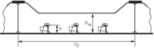
Figure 2.10.5 Parameter definition for web stiffening
10.16 Plated structures
10.16.1 Plated
structures are those stiffened plate elements in contact with the
hull and subject to ice loads. These requirements are applicable to
an inboard extent which is the lesser of:
-
web height of
adjacent parallel web frame or stringer; or
-
2,5 times the
depth of framing that intersects the plated structure.
10.16.2 The
thickness of the plating and the scantlings of attached stiffeners
are to be such that the degree of end fixity necessary for the shell
framing is ensured.
10.17 Corrosion/abrasion additions and steel renewal
10.17.1 Effective protection against corrosion and ice-induced abrasion is
recommended for all external surfaces of the shell plating for Polar Class ships.
10.17.3 Polar Class ships are to have a minimum corrosion/abrasion addition of
ts = 1,0 mm applied to all internal structures within the ice
strengthened hull areas, including plated members adjacent to the shell, as well as
stiffener webs and flanges.
10.17.4 Steel renewal for ice strengthened structures is required when the gauged
thickness is less than tn + 0,5 mm.
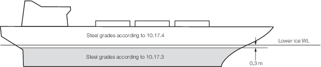
Figure 2.10.6 Steel grade requirements for submerged and weather exposed shell plating
Table 2.10.7 Corrosion/abrasion additions for shell plating
| Hull
area
|
t
s, in
mm
|
| With effective protection
|
Without effective protection
|
|
PC1 to PC3
|
PC4 and PC5
|
PC6 and PC7
|
PC1 to PC3
|
PC4 and PC5
|
PC6 and PC7
|
| Bow;
Bow Intermediate Icebelt
|
3,5
|
2,5
|
2,0
|
7,0
|
5,0
|
4,0
|
| Bow Intermediate
Lower; Midbody & Stern Icebelt
|
2,5
|
2,0
|
2,0
|
5,0
|
4,0
|
3,0
|
| Midbody and
Stern Lower; Bottom
|
2,0
|
2,0
|
2,0
|
4,0
|
3,0
|
2,5
|
10.18 Materials
10.18.5 Castings
are to have specified properties consistent with the expected service
temperature for the cast component.
Table 2.10.8 Material classes for structural
members of polar ships
| Structural members
|
Material Class
|
| Shell plating
within the bow and bow intermediate icebelt hull areas (B, BIi
)
|
II
|
| Plating materials
for stem and stern frames, rudder horn, rudder, propeller nozzle, shaft
brackets, ice skeg, ice knife and other appendages subject to ice impact
loads
|
II
|
| All weather and sea
exposed SPECIAL, as defined in Table 2.2.1 Material classes and
grades inPt 3, Ch 2 Materials, structural members within
0,2L from FP
|
II
|
| All weather and sea
exposed SECONDARY and PRIMARY, as defined in Table 2.2.1 Material classes and
grades inPt 3, Ch 2 Materials, structural members outside
0,4L amidships
|
I
|
| All inboard framing
members attached to the weather and sea-exposed plating including any
contiguous inboard member within 600 mm of the plating
|
I
|
| Weather-exposed
plating and attached framing in cargo holds of ships which by nature of
their trade have their cargo hold hatches open during cold weather
operations
|
I
|
Table 2.10.9 Steel grades for weather exposed
plating
|
Thickness, t
mm
|
Material Class I
|
|
PC1 to 5
|
PC6 and 7
|
| MS
|
HT
|
MS
|
HT
|
|
t ≤ 10
|
B
|
AH
|
B
|
AH
|
| 10 < t ≤ 15
|
B
|
AH
|
B
|
AH
|
| 15 < t ≤ 20
|
D
|
DH
|
B
|
AH
|
| 20 < t ≤ 25
|
D
|
DH
|
B
|
AH
|
| 25 < t ≤ 30
|
D
|
DH
|
B
|
AH
|
| 30 < t ≤ 35
|
D
|
DH
|
B
|
AH
|
| 35 < t ≤ 40
|
D
|
DH
|
D
|
DH
|
| 40 < t ≤ 45
|
E
|
EH
|
D
|
DH
|
| 45 < t ≤ 50
|
E
|
EH
|
D
|
DH
|
Note Includes weather exposed plating of hull structures and
appendages, as well as their outboard framing members, situated above
a level of 0,3 m below the lowest ice waterline.
|
Table 2.10.10 Steel grades for weather exposed
plating
|
|
Material Class II
|
|
Thickness, t
mm
|
PC1 to 5
|
PC6 and 7
|
|
|
MS
|
HT
|
MS
|
HT
|
|
t ≤ 10
|
B
|
AH
|
B
|
AH
|
| 10 < t ≤ 15
|
D
|
DH
|
B
|
AH
|
| 15 < t ≤ 20
|
D
|
DH
|
B
|
AH
|
| 20 < t ≤ 25
|
D
|
DH
|
B
|
AH
|
| 25 < t ≤ 30
|
E
|
EH, see
Note 2
|
D
|
DH
|
| 30 < t ≤ 35
|
E
|
EH
|
D
|
DH
|
| 35 < t ≤ 40
|
E
|
EH
|
D
|
DH
|
| 40 < t ≤ 45
|
E
|
EH
|
D
|
DH
|
| 45 < t ≤ 50
|
E
|
EH
|
D
|
DH
|
Note
1. Includes weather exposed plating of
hull structures and appendages, as well as their outboard framing
members, situated above a level of 0,3 m below the lowest ice
waterline.
Note
2. Grades D, DH are allowed for a single
strake of side shell plating not more than 1,8 m wide from 0,3 m below
the lowest ice waterline.
|
Table 2.10.11 Steel grades for weather exposed
plating
| Thickness, t mm
|
Material Class III
|
|
PC1 to 3
|
PC4 and 5
|
PC6 and 7
|
| MS
|
HT
|
MS
|
HT
|
MS
|
HT
|
|
t ≤ 10
|
E
|
EH
|
E
|
EH
|
B
|
AH
|
| 10 < t ≤ 15
|
E
|
EH
|
E
|
EH
|
D
|
DH
|
| 15 < t ≤ 20
|
E
|
EH
|
E
|
EH
|
D
|
DH
|
| 20 < t ≤ 25
|
E
|
EH
|
E
|
EH
|
D
|
DH
|
| 25 < t ≤ 30
|
E
|
EH
|
E
|
EH
|
E
|
EH
|
| 30 < t ≤ 35
|
E
|
EH
|
E
|
EH
|
E
|
EH
|
| 35 < t ≤ 40
|
F
|
FH
|
E
|
EH
|
E
|
EH
|
| 40 < t ≤ 45
|
F
|
FH
|
E
|
EH
|
E
|
EH
|
| 45 < t ≤ 50
|
F
|
FH
|
F
|
FH
|
E
|
EH
|
Note Includes weather exposed plating of hull structures and
appendages, as well as their outboard framing members, situated above
a level of 0,3 m below the lowest ice waterline.
|
10.19 Longitudinal strength – Application
10.19.1 A ramming impact on the bow is the design scenario for the evaluation of the
longitudinal strength of the hull.
10.19.3 Ice loads are only to be combined with still water loads. The combined
stresses are to be compared against permissible bending and shear stresses at different
locations along the ship's length. In addition, sufficient local buckling strength is
also to be verified.
10.20 Design vertical ice force at the bow
10.20.1 The design vertical ice force at the bow, FIB, is to be
taken as the lesser of FIB, 1 or FIB, 2:
|
FIB, 1
|
= |
 |
where
|
K
I
|
= |
indentation parameter |
|
|
= |

|
|
K
f
|
= |
for blunt bow forms:
 - for wedge bow forms (αs < 80 deg), eb = 1 and the
above simplifies to:

|
|
|
= |
An approximate eb determined
by a simple fit is acceptable
|
|
|
= |
1,0 for a simple
wedge bow form |
|
|
= |
0,4 to 0,6 for
a spoon bow form |
|
|
= |
0 for a landing
craft bow form |
|
γs
|
= |
stem
angle to be measured between the horizontal axis and the stem tangent
at the upper ice waterline, in degrees (buttock angle as per Figure 2.10.2 Definition of hull angles measured on the centreline)
|
|
C
|
= |

|
|
BUI |
= |
the greatest moulded breadth corresponding to the upper ice waterline
(UIWL), in metres |
|
L
B
|
= |
bow length, in m, used in the equation: |
|
A
wp
|
= |
waterplane area corresponding to the upper ice waterline (UIWL), in
m2
|
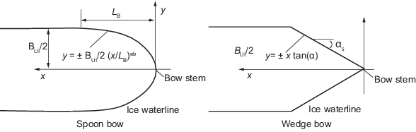
Figure 2.10.7 Bow shape definition
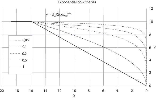
Figure 2.10.8 Illustration of effect on the bow
shape eb, for B = 20 and LB = 16
10.21 Design vertical shear force
10.21.1 The
design vertical ice shear force, F
I, along
the hull girder is to be taken as:
where
|
C
f
|
= |
longitudinal distribution factor to be taken as follows: |
- Positive shear force
|
C
f
|
= |
0,0 between the aft end of LUI and
0,6LUI from aft |
|
C
f
|
= |
1,0 between 0,9LUI from aft and the forward
end of L
UI |
- Negative shear force
|
Cf
|
= |
0,0 at the aft end of LUI
|
|
Cf
|
= |
-0,5 between 0,2LUI and 0,6
LUI from aft |
|
Cf
|
= |
0,0 between 0,8LUI from aft and the forward
end of LUI
|
Intermediate values are to be determined by linear
interpolation.
10.21.2 The
applied vertical shear stress, τa, is to be determined
along the hull girder in a similar manner as in Pt 3, Ch 4 Longitudinal Strength by substituting the design
vertical ice shear force for the design vertical wave shear force.
10.22 Design vertical ice bending moment
10.22.1 The design vertical ice bending moment, MI, along the hull
girder is to be taken as:
|
MI
|
= |
0,1 Cm
LUI sin–0,2(γs) FIB MNm |
where
|
FIB
|
= |
design vertical ice force at the bow, in MN |
|
Cm
|
= |
longitudinal distribution factor for design vertical ice bending
moment to be taken as follows: |
|
Cm |
= |
0,0 at the aft end of LUI
|
|
Cm
|
= |
1,0 between 0,5LUI and 0,7LUI
from aft |
|
Cm |
= |
0,3 at 0,95LUI from aft |
|
C
m |
= |
0,0 at the forward end of LUI
|
- Intermediate values are to be determined by linear interpolation.
10.22.2 The applied vertical bending stress, σa, is to be determined
along the hull girder in a similar manner as in Pt 3, Ch 4 Longitudinal Strength, by substituting the design vertical ice bending moment for
the design vertical wave bending moment. The ship still water bending moment is to be
taken as the permissible still water bending moment in sagging condition.
10.23 Longitudinal strength criteria
10.23.1 The
strength criteria provided in Table 2.10.12 Longitudinal strength
criteria are to be satisfied. The design stress is not to exceed
the permissible stress.
Table 2.10.12 Longitudinal strength
criteria
| Failure mode
|
Applied stress
|
Permissible
stress
|
Permissible
stress
|
|
|
|
| Tension
|
σa
|
η σy
|
η
0,41(σu + σy)
|
| Shear
|
τa
|
|
|
| Buckling
|
σa
|
σ
|
for plating and
for web plating of stiffeners
|
|
|
|
|
for
stiffeners
|
|
|
τa
|
τc
|
| Symbols
|
|
σa
|
= |
applied vertical bending stress, in N/mm2
|
|
|
τa
|
= |
applied vertical shear stress, in N/mm2
|
|
|
σy
|
= |
minimum upper yield stress of the material, in
N/mm2
|
|
|
σu
|
= |
ultimate tensile strength of material, in
N/mm2
|
|
|
|
|
|
|
η |
= |
0,8 |
| = |
0,6 for ships which are assigned the additional
notation Icebreaker |
|
10.24 Stem and stern frames
10.25 Rudders
10.25.1 Rudder scantlings, posts, rudder horns, solepieces, rudder stocks,
steering engines, and pintles are to be dimensioned in accordance with Pt 3, Ch 6 Aft End Structure and Pt 3, Ch 13 Ship Control Systems as appropriate. The speed used in the calculations
is to be the maximum service speed or that given in Table 2.10.13 Minimum speed, whichever is the
greater. When used in association with the speed given in Table 2.10.13 Minimum speed, the rudder profile
coefficients are to be taken as 1,1.
10.25.2 For the astern condition the actual astern speed or half the minimum
speed defined in Table 2.10.13 Minimum speed is to
be used, whichever is greater.
10.25.4 Local scantlings of rudders are to be determined considering that the
rudder belongs to the stern ice belt/ice belt lower, depending on rudder location
with respect to the lower extent of the ice belt. Rudder local plating and framing
located above the lower extent of the main ice belt are to be dimensioned using the
stern ice belt area factor applicable to the relevant Polar Class. Rudder local
plating and framing located below the lower extent of the main ice belt are to be
dimensioned using the stern lower ice belt area factor applicable to the relevant
Polar Class.
10.25.5 For scantlings of the rudder blade the plate thickness is to be
determined in accordance with Pt 8, Ch 2, 10.10 Shell plate requirements using the
rudder web frame spacing. The aspect ratio of the panel under consideration is to be
used to determine the appropriate selection of formulae for transverse or
longitudinally framed plating. Where the aspect ratio is 1,0, the panel is to be
considered transversely framed.
10.25.6 The vertical and horizontal web thickness is not to be less than
0,7tR, but is not to be taken as less than 8 mm, where
tR is the rudder plate thickness.
10.25.7 The mainpiece is to be dimensioned in accordance with Pt 3, Ch 13 Ship Control Systems, utilising the basic stock diameter
derived using in the minimum speed in Table 2.10.13 Minimum speed.
Table 2.10.13 Minimum speed
| Ice
Class
|
Minimum
speed, in knots
|
Ice
Class
|
Minimum
speed, in knots
|
| PC7
|
18
|
Icebreaker,
PC7
|
22
|
| PC6
|
20
|
Icebreaker,
PC6
|
24
|
| PC5
|
22
|
Icebreaker,
PC5
|
28
|
| PC4
|
25
|
Icebreaker,
PC4
|
32
|
| PC3
|
28
|
Icebreaker,
PC3
|
35
|
| PC2
|
31
|
Icebreaker,
PC2
|
38
|
| PC1
|
34
|
Icebreaker,
PC1
|
42
|
10.26 Appendages
10.26.1 All
appendages are to be designed to withstand forces appropriate for
the location of their attachment to the hull structure or their position
within a hull area.
10.27 Local details
10.27.1 Local
design details are to be suitably designed to transfer ice-induced
loads to supporting structure (bending moments and shear forces).
10.27.2 The
loads carried by a member in way of cut-outs are not to cause instability.
Where necessary, the structure is to be stiffened.
10.28 Direct calculations
10.28.2 Direct calculations are to be used for load carrying stringers and web frames forming
part of a grillage system.
10.28.3 Where direct calculation is used to check the strength of structural
systems, the load patch specified in Pt 8, Ch 2, 10.3 Design ice loads – General is
to be applied, without being combined with any other loads. The load patch is to be
applied at locations where the capacity of these members under the combined effects of
bending and shear is minimised. Special attention is to be paid to the shear capacity in
way of lightening holes and cut-outs in way of intersecting members.
10.28.5 If the structure is evaluated based on linear calculation methods, the
following are to be considered:
- Web plates and flange elements in compression and shear to fulfil
relevant buckling criteria in accordance with the applicable ShipRight SDA
procedures. See
Pt 3, Ch 16, 3 Structural design assessment.
- Nominal shear stresses in member web plates to be less than
sy/√3
- Nominal von Mises stresses in member flanges to be less than 1,15
sy
10.28.6 If the structure is evaluated based on non-linear calculation methods, the following are
to be considered:
- The analysis is to reliably capture buckling and plastic deformation of the
structure.
- The acceptance criteria are to ensure a suitable margin against fracture and
major buckling and yielding causing significant loss of stiffness.
- Permanent lateral and out-of plane deformation of considered member are to be
minor relative to the relevant structural dimensions.
10.29 Welding
10.29.1 All
welding within ice-strengthened areas is to be of the double continuous
type.
10.29.2 Continuity
of strength is to be ensured at all structural connections.
|