
Section
3 Materials for equipment and components at low temperatures –
Winterisation M
3.1 Scope
3.1.1 The following requirements are intended for the materials of equipment and
components exposed to the external design air temperature.
3.1.2 The suitability
may be demonstrated by one or a combination of a number of ways, including,
but not limited to, the following:
-
Based on these requirements.
-
Based on international or
national Standards.
-
Technical investigations
based on engineering principles.
-
Service experience at the
operating temperature.
-
Mechanical tests (e.g. Charpy
impact tests).
3.2 Documentation
3.2.1 Documentation
is to be submitted that demonstrates the suitability of exposed equipment
and components at low temperatures.
3.3 Equipment and components
3.3.1 The equipment
and components of exposed members identified in Table 1.3.1 List of equipment and
components and Figure 1.3.1 Mooring and anchoring
sub-components are to comply with Ch 1, 3.4 Plating for
plating, Ch 1, 3.5 Piping, valves and fittings for piping, valves and fittings,
and Ch 1, 3.6 Forging and castings for forgings and castings, as
appropriate.
Table 1.3.1 List of equipment and
components
| Main component
|
Sub-component
|
Class
|
|
Deck machinery and equipment
|
| Windlass
|
Cable lifter
|
II
|
| Gear wheel
|
II
|
| Shaft
|
II
|
| Casing
|
I
|
| Foundation bolt
|
II
|
| Brake system
|
II
|
| Stripper bar
|
II
|
| Mooring winches
|
Gear wheel
|
II
|
| Shaft
|
II
|
| Casing
|
I
|
| Foundation bolt
|
II
|
| Winch motors
|
Hydraulics piping
|
II
|
| Hoses
|
II
|
| Winch controls
|
Hydraulics
|
II
|
| Bollards/fairleads/bits
|
|
III
|
| Anchor chain, see Note 3
|
|
II
|
| Anchor
|
Crown/head, shackle &
shank
|
II
|
| Crown/head pin & shackle/swivel
pin
|
I
|
| Anchor lashing
|
|
II
|
| Chain stopper
|
|
II
|
| Emergency towing system, see
Note 2
|
|
I
|
|
Cargo handling systems
|
| Cargo lines
|
Pipe
|
II
|
| Flange
|
II
|
| Valve
|
II
|
| Gaskets
|
I
|
| Bolts
|
I
|
| Cargo loading manifold
|
|
I
|
| Cargo heating steam
line
|
Pipe
|
II
|
| Flange
|
II
|
| Valve
|
II
|
| Bolts
|
I
|
| Hydraulic oil pipes for cargo valve
remote control
|
|
II
|
| Inert gas piping
|
|
I
|
|
Hull piping systems
|
| Bunker lines to engine
room
|
Pipe
|
I
|
| Flange
|
I
|
| Valve
|
I
|
| Bolts
|
I
|
| Control air pipes
|
|
I
|
|
Fire-fighting systems
|
| Fire main
|
Pipe
|
I
|
| Flange
|
I
|
| Valve
|
I
|
| Bolts
|
I
|
| Water spray
systems
|
Pipe
|
II
|
| Flange
|
II
|
| Valve
|
II
|
| Foam systems
|
|
I
|
| Emergency fire pump
|
|
I
|
| Hydrants
|
|
I
|
| Hydrant pipes
|
|
II
|
| Fire flaps
|
|
I
|
|
Access on deck
|
| Handrails
|
|
I
|
| Structures on deck to provide shelter
from seas/weather when working on deck during passage (excluding deckhouses
and forecastles)
|
|
I
|
| Access doors and hatches
– hinges/dogs, etc. to accommodation and forecastle
|
Dogs/hinges
|
I
|
| Seals
|
I
|
| Stairs
|
|
I
|
Note
1. Additional sub-components associated
with the main component, which are not specified, are to be of a
similar class to an equivalent sub-component which is specified.
Note
2. Where the ETA is integrated with the
bollards/fairleads/bits, the higher class is to be applied.
Note
4. A lower risk class may be accepted
whereby it can be demonstrated from available experience and
mitigation measures, where such are in place, that these measures
would provide a level of protection that mitigates the risk, or
whereby a risk assessment was undertaken for a specific vessel
type/arrangement as in Winterisation MEn. Conversely, a higher risk
class may be required for the same reason.
|
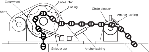
Figure 1.3.1 Mooring and anchoring
sub-components
3.4 Plating
3.4.3 The following
is to be used for determining the material certification for steel
plates, strips, sections and bars used in machinery and systems components:
3.5 Piping, valves and fittings
3.5.1
Table 1.3.2 Charpy
testing temperature (°C) for Class I, Table 1.3.3 Charpy
testing temperature (°C) for Class II and Table 1.3.4 Charpy
testing temperature (°C) for Class III are to be used for determining the Charpy testing
temperature for steel piping, valves and fittings used in machinery and systems
components, in association with Pt 5, Ch 12 Piping Design Requirements of the Rules and Regulations for the Classification of Ships, July 2022. As an
alternative for Class I, steel may be to a national or international Standard showing
equivalence to the Rules for the Manufacture, Testing and Certification of Materials, July 2022.
Table 1.3.2 Charpy
testing temperature (°C) for Class I
| Thickness, mm
|
External design air temperature
|
| –33°C to –38°C
|
–39°C to –48°C
|
–49°C to –58°C
|
–59°C to –68°C
|
|
t ≤ 10
|
0
|
0
|
–20
|
–20
|
| 10 < t ≤ 15
|
0
|
–20
|
–20
|
–20
|
| 15 < t ≤ 20
|
0
|
–20
|
–20
|
–40
|
| 20 < t ≤ 25
|
–20
|
–20
|
–20
|
–40
|
| 25 < t ≤ 30
|
–20
|
–20
|
–40
|
–40
|
| 30 < t ≤ 35
|
–20
|
–20
|
–40
|
–40
|
| 35 < t ≤ 45
|
–20
|
–40
|
–40
|
–60
|
| 45 < t ≤ 50
|
–40
|
–40
|
–60
|
–60
|
Table 1.3.3 Charpy
testing temperature (°C) for Class II
| Thickness, mm
|
External design air temperature
|
| –33°C to –38°C
|
–39°C to –48°C
|
–49°C to –58°C
|
–59°C to –68°C
|
|
t ≤ 10
|
0
|
–20
|
–20
|
–40
|
| 10 < t ≤ 20
|
–20
|
–20
|
–40
|
–40
|
| 20 < t ≤ 30
|
–20
|
–40
|
–40
|
–60
|
| 30 < t ≤ 40
|
–40
|
–40
|
–60
|
–60
|
| 40 < t ≤ 45
|
–40
|
–60
|
–60
|
n/a
|
| 45 < t ≤ 50
|
–40
|
–60
|
–60
|
n/a
|
Table 1.3.4 Charpy
testing temperature (°C) for Class III
| Thickness, mm
|
External design air temperature
|
| –33°C to –38°C
|
–39°C to –48°C
|
–49°C to –58°C
|
–59°C to –68°C
|
|
t ≤ 10
|
–20
|
–20
|
–40
|
–40
|
| 10 < t ≤ 20
|
–20
|
–40
|
–40
|
–60
|
| 20 < t ≤ 25
|
–40
|
–40
|
–60
|
–60
|
| 25 < t ≤ 30
|
–40
|
–40
|
–60
|
–60
|
| 30 < t ≤ 35
|
–40
|
–60
|
–60
|
n/a
|
| 45 < t ≤ 40
|
–40
|
–60
|
–60
|
n/a
|
| 40 < t ≤ 50
|
–60
|
–60
|
n/a
|
n/a
|
3.5.3 In general, the
minimum average Charpy impact average energy (J) is to be 10 per cent
of the specified minimum yield strength (N/mm2) up to a
maximum of 50 J.
3.5.4 The following
is to be used for determining the material certification for steel
piping, valves and fittings used in machinery and systems components,
in association with Pt 5, Ch 12 Piping Design Requirements:
Class I – Manufacturer’s certificate
This is to be in accordance with Ch 1, 3.1 General 3.1.3.(c) of the Rules for the Manufacture, Testing and Certification of Materials, July 2022.
Classes II and III – LR Certificate or
Manufacturer’s certificate validated by LR
This is to be in accordance with Ch 1, 3.1 General 3.1.3 or Ch 1, 3.1 General 3.1.3.(b) of the Rules for the Manufacture, Testing and Certification of Materials, July 2022, as appropriate.
3.6 Forging and castings
3.6.1
Table 1.3.5 Charpy testing temperature (°C)
for all classes is to be used for determining
the Charpy testing temperature for steel forgings and castings used
in exposed machinery and systems components.
Table 1.3.5 Charpy testing temperature (°C)
for all classes
| Material class
|
External design air temperature
|
| –33°C to
–38°C
|
–39°C and
below
|
| Class I or II
|
–20
|
To be specially
considered
|
| Class III
|
–40
|
Note For components manufactured and installed without welding,
the test temperature may be increased by +20°C, but is not to be taken
higher than 0°C.
|
3.6.2 In general, the minimum average Charpy impact energy is to be greater than
( E + f) in Joules (J), where
-
E is the minimum average energy value:
27J for steels with
specified minimum yield strength less than 300 N/mm2;
34J for steels with specified minimum yield strength equal to or
greater than 300 N/mm2
- f is m multiplied by the difference between the required test
temperature as given in Table 1.3.6 Example of required test
criteria and the certified test temperature to be
shown on the test certificate
- m is the slope of the transition curve; for steels, m is taken as
a value of 3.
An alternative value of m may be used where
material impact transition properties have been demonstrated from either a single
supplier of known consistency or a number of suppliers (minimum of three) where a
lower bound approach is taken to a series of transition curves
For example, for steel with a specified minimum yield strength less than
300 N/mm2 and where the external design air temperature is equal to –40°C for
a Class III component, the Charpy testing temperature and criteria may be taken as shown
in Table 1.3.6 Example of required test
criteria.
Table 1.3.6 Example of required test
criteria
Required Charpy
test temperature
°C
|
Minimum energy
value, E,
J
|
Certified Charpy
test temperature
°C
|
Transition
slope
value, m
|
Difference in
test
temperature multiplied
by m,
f, °C
|
Criteria
for
Charpy impact energy,
J
|
| –40
|
27
|
–40
|
3
|
0
|
27
|
| –40
|
27
|
–20
|
3
|
60
|
87
|
| –40
|
27
|
+0
|
3
|
120
|
147
|
3.6.3 Where a component has dedicated heating arrangements that protect the
entire component, the Charpy testing temperature may be taken as 20°C above the required
Charpy testing temperature at an external design air temperature of -33°C and as a Class
I/II component.
3.6.4 Cast iron is not
permitted.
3.7 Other materials
3.7.1 The testing requirements
for piping, valves and fittings used in machinery and systems components
of other materials will be specially considered in accordance with
the manufacturer’s recommendations.
|