
Section
2 Materials for hull construction at low temperatures – Winterisation
H
2.1 Hull construction materials
2.1.4 In addition to the requirements of Table 1.2.1 Material classes and
grades and Figure 1.2.1 Distribution of material classes for cold weather, miscellaneous attachments are to comply with
Table 1.2.5 Material classes and
grades.
Table 1.2.1 Material classes and
grades
| Structural member category
|
Material
class
|
| Within 0,4L amidships
|
Outside 0,4L amidships
|
SECONDARY:
- Deck plating exposed to weather, in general
- Side plating above CWL, see Note 5
- Transverse bulkheads above CWL, see Notes 5 and
6
|
I
|
I
|
PRIMARY:
- Strength deck plating
- Continuous longitudinal members above strength deck,
excluding longitudinal hatch coamings
- Longitudinal bulkhead above CWL, see Notes 5 and
6
- Top wing tank bulkhead above CWL, see Notes 5 and
6
|
II
|
I
|
SPECIAL:
- Sheerstrake at strength deck, see Note 1
- Stringer plate in strength deck, see Note 1
- Deck strake at longitudinal bulkhead, see Note 2
- Continuous longitudinal hatch coamings, see Note
3
|
III
|
II
|
Note
1. Not to be less than Grade E/EH within
0,4L amidships in ships with length exceeding 250 m.
Note
2. In ships with breadth exceeding 70 m
at least three deck strakes are to be Class III.
Note
3. Not to be less than Grade D/DH.
Note
4. Within 0,4L amidships, single
strakes which are required to be of Class III or of Grade E/EH or FH
are to have breadths not less than 800 + 5L, but need not be
greater than 1800 mm.
Note 6. Applicable to
plating attached to hull envelope plating exposed to cold air. At least
one strake is to be considered in the same way as exposed plating and the
strake width is to be at least 600 mm. If thermal stress calculations are
performed then the extent of plate requiring consideration is to be
adjusted accordingly.
|
Table 1.2.2 Materials for Class I
| Thickness,
mm
|
External design air temperature
|
| −24°C to −28°C
|
–29°C to –38°C
|
–39°C to –48°C
|
–49°C to –58°C
|
–59°C to –68°C
|
| MS
|
HT
|
MS
|
HT
|
MS
|
HT
|
MS
|
HT
|
MS
|
HT
|
| t ≤ 10
|
A
|
AH
|
A
|
AH
|
B
|
AH
|
D
|
DH
|
D
|
DH
|
| 10 <
t ≤ 15
|
A
|
AH
|
B
|
AH
|
D
|
DH
|
D
|
DH
|
D
|
DH
|
| 15
< t ≤ 20
|
A
|
AH
|
B
|
AH
|
D
|
DH
|
D
|
DH
|
E
|
EH
|
| 20 <
t ≤ 25
|
B
|
AH
|
D
|
DH
|
D
|
DH
|
D
|
DH
|
E
|
EH
|
| 25
< t ≤ 30
|
B
|
AH
|
D
|
DH
|
D
|
DH
|
E
|
EH
|
E
|
EH
|
| 30
< t ≤ 35
|
D
|
DH
|
D
|
DH
|
D
|
DH
|
E
|
EH
|
E
|
EH
|
| 35
< t ≤ 45
|
D
|
DH
|
D
|
DH
|
E
|
EH
|
E
|
EH
|
n/a
|
FH
|
| 45
< t ≤ 50
|
D
|
DH
|
E
|
EH
|
E
|
EH
|
n/a
|
FH
|
n/a
|
FH
|
|
Note 2. MS and HT are defined as Mild Steel and High Tensile Steel
respectively.
|
Table 1.2.3 Materials for Class II
| Thickness, mm
|
External design air temperature
|
| −24°C to −28°C
|
−29°C to −38°C
|
−39°C to −48°C
|
−49°C to −58°C
|
−59°C to −68°C
|
| MS
|
HT
|
MS
|
HT
|
MS
|
HT
|
MS
|
HT
|
MS
|
HT
|
| t ≤
10
|
A
|
AH
|
B
|
AH
|
D
|
DH
|
D
|
DH
|
E
|
EH
|
| 10 < t ≤
20
|
B
|
AH
|
D
|
DH
|
D
|
DH
|
E
|
EH
|
E
|
EH
|
| 20 < t ≤
30
|
D
|
DH
|
D
|
DH
|
E
|
EH
|
E
|
EH
|
n/a
|
FH
|
| 30 < t ≤
40
|
D
|
DH
|
E
|
EH
|
E
|
EH
|
n/a
|
FH
|
n/a
|
FH
|
| 40 < t ≤
45
|
E
|
EH
|
E
|
EH
|
n/a
|
FH
|
n/a
|
FH
|
n/a
|
n/a
|
| 45 < t ≤
50
|
E
|
EH
|
E
|
EH
|
n/a
|
FH
|
n/a
|
FH
|
n/a
|
n/a
|
|
Note 2. MS and HT are defined as Mild Steel and High Tensile Steel
respectively.
|
Table 1.2.4 Materials for Class III
| Thickness, mm
|
External design air temperature
|
| −24°C to −28°C
|
−29°C to −38°C
|
−39°C to −48°C
|
−49°C to −58°C
|
−59°C to −68°C
|
| MS
|
HT
|
MS
|
HT
|
MS
|
HT
|
MS
|
HT
|
MS
|
HT
|
| t ≤
10
|
B
|
AH
|
D
|
DH
|
D
|
DH
|
E
|
EH
|
E
|
EH
|
| 10 < t ≤
20
|
D
|
DH
|
D
|
DH
|
E
|
EH
|
E
|
EH
|
n/a
|
FH
|
| 20 < t ≤
25
|
D
|
DH
|
E
|
EH
|
E
|
EH
|
E
|
FH
|
n/a
|
FH
|
| 25 < t ≤
30
|
D
|
DH
|
E
|
EH
|
E
|
EH
|
n/a
|
FH
|
n/a
|
FH
|
| 30 < t ≤
35
|
E
|
EH
|
E
|
EH
|
n/a
|
FH
|
n/a
|
FH
|
n/a
|
n/a
|
| 35 < t ≤
40
|
E
|
EH
|
E
|
EH
|
n/a
|
FH
|
n/a
|
FH
|
n/a
|
n/a
|
| 40 < t ≤
50
|
E
|
EH
|
n/a
|
FH
|
n/a
|
FH
|
n/a
|
n/a
|
n/a
|
n/a
|
|
Note 2. MS and HT are defined as Mild Steel and High Tensile Steel
respectively.
|
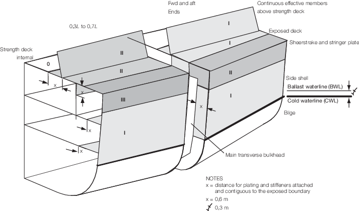
Figure 1.2.1 Distribution of material classes for cold weather
Table 1.2.5 Material classes and
grades
| Structural member
|
External design air temperature for structural member °C
|
Material class
|
| Exposed structures of length greater than
0,09L and subjected to hull girder stress
|
t
|
Constructed of the same material class to that of
the material to which they are attached, however need not be greater than
class II
|
| Hatch coamings, hatch covers, crane pedestals
and windlass seats
|
t + 5
|
Constructed of the same material class to that
of the material to which they are attached, or class II, whichever is the
greater
|
| Forecastle deck
|
t + 10
|
Class II
|
| External bulkheads of
accommodation block
|
t + 20
|
Class II
|
| Forecastle side shell plating
|
| Plating and stiffeners attached and contiguous to
the exposed boundary plating distance 'x', see
Figure 1.2.1 Distribution of material classes for cold weather and Note 2
|
t + 10
|
Class I, but need not be taken greater than D or
DH
|
| Other exposed structures of length
less than 0,09L, e.g. bulwarks, breakwaters, unlagged gas turbine
intake structures, side screens, etc.
|
Need not be taken lower than –33
|
Class I
|
| Stern frames, rudders,
rudder horns, shaft brackets and stem (including the strake of shell plating
to which the item is attached)
|
Fully
immersed
|
t + 20
|
Class II
|
| Periodically
immersed or exposed
|
t
|
Note
1. For built-up stiffeners within the
distance ‘x’, the web and flange are considered to be a single
stiffening member and both members are to comply with the material
requirements. For bulb stiffeners and stiffeners with the flange
outside the distance ‘x’, the web only may be required to comply with
the material requirements.
|
2.1.5 Steel plate materials for stern frames, rudders, rudder horns, shaft brackets, and stem
(including the strake of shell plating to which the item is attached) and internal
members attached to these items are to be in accordance with Table 1.2.2 Materials for Class I, Table 1.2.3 Materials for Class II and
Table 1.2.4 Materials for Class III, using the appropriate
temperature in Table 1.2.5 Material classes and
grades. The steel casting and
forging materials for the rudders, rudder stocks, rudder horns, shaft brackets, stern
frames and stem are to be in accordance with Table 1.2.2 Materials for Class I, Table 1.2.3 Materials for Class II and Table 1.2.4 Materials for Class III, using the appropriate
temperature in Table 1.2.6 Steel casting and forging materials for rudder, rudder horn, rudder stock, shaft
bracket, stern.
2.1.7 Welding consumables are to be suitable for the applicable steel grades,
see
Ch 11 Approval of Welding Consumables of the Rules for the Manufacture, Testing and Certification of Materials, July 2022.
Table 1.2.6 Steel casting and forging materials for rudder, rudder horn, rudder stock, shaft
bracket, stern
| Item
|
Condition
|
External design air temperature for
item,°C
|
Steel grade (see Notes 1,2
and 3)
|
| Casting
|
Forging
|
| Rudder horn & Shaft brackets
|
Fully immersed
|
t + 20
|
Special Grade
|
Structural
|
| Periodically immersed or exposed
|
t
|
Ferritic Grade or Ni steel
|
Ferritic
|
| Rudder & Rudder stock
|
Fully immersed
|
t + 20
|
Normal Grade
|
Structural
|
| Periodically immersed or exposed
|
t
|
Ferritic Grade or Ni steel
|
Ferritic
|
| Stern frame
|
Fully immersed
|
t + 20
|
Special Grade
|
Structural
|
| Periodically immersed or exposed
|
t
|
Ferritic Grade
|
Ferritic
|
| Stem, (including the strake of shell plating to which the
item is attached)
|
Fully immersed
|
t + 20
|
Normal Grade
|
Structural
|
| Periodically immersed or exposed
|
t
|
Ferritic Grade or Ni steel
|
Ferritic
|
|
|
|