
Section
4 Survey during construction
4.1 Quality control and quality assurance
4.1.1 Surveyors should
discuss and establish with the Builder, a satisfactory routine for
quality control and survey throughout the various stages of construction.
Records should be kept by the Builders, and made available to the
Surveyors.
4.1.2 Builders may
apply for approval under the Quality Assurance Scheme for Hull Construction.
4.2 Ship construction standards
4.2.1 The general
tolerance and construction standards are to be in accordance with
the requirements of this section, and other approved standards agreed.
4.2.2 Tolerances
to be used for construction misalignment for all material are to be
discussed between Owners/ Builders and the Surveyor, and acceptable
Standards agreed, subject to the requirements of this Chapter or Naval
Authority requirements where applicable. The permitted degree of inaccuracy/
misalignment will vary according to whether the defect is:
-
In primary structure.
-
In secondary structure.
-
Required for equipment
alignment.
-
Cosmetic.
4.2.3 In addition,
certain critical locations identified by the plan approval process
may be subject to specific construction tolerances which will require
to be recorded in accordance with the procedures.
4.2.4 All workmanship
is to be of good quality and in accordance with good shipbuilding
practice. Any defect is to be rectified to the satisfaction of the
Surveyor before the material is covered with paint, cement or other
composition. The materials and welding are to be in accordance with
the requirements of the Rules for Materials. Plates which have been
subjected to excessive heating while being worked are to be satisfactorily
heat treated before being erected in the hull.
4.2.5 In shipyards
certified under the LR Quality Assurance Scheme, the standards will
have received general approval as part of the certification procedures
and their application to particular vessels should be included in
the Quality Plan submitted to the local Surveyors for approval.
4.3 Prefabrication
4.3.1 Surveyors will
attend in the early stages of construction to ensure that undesirable
procedures and faulty workmanship are avoided, and possible consequences
minimized. When the existence of defects is noticed, prompt and suitable
measures should be taken to ensure rectification. Where, due to circumstances,
major prefabrication of units has been carried out without inspection
by LR, then Headquarters should be advised immediately, such advice
including details of the circumstances.
4.3.2 Throughout
the preparation of material and assembly of prefabricated units, workmanship
is to be inspected to ensure that correct procedures are being followed.
Surveyors will liaise with the Design Offices and the Quality Control
Departments to ensure that any plan approval comments are incorporated
and that attention is given to details which are not shown on the
approved plans (e.g. air and drainage holes, etc.) during early material
preparation stages.
4.3.3 Surveyors should
bear in mind that visual examination of welds and plating of a finished
structure does not necessarily ensure a complete and satisfactory
survey. Surveyors should ensure that adequate inspection is made of
joint preparation before welding. Attention is drawn to the guidance
on welding and structural details in Vol 1, Pt 6, Ch 6 Material and Welding Requirements of the Rules for Naval Ships. Regular examination,
in conjunction with the Builder, of radiographic records provides
a check on the quality of welding operations and any decline in standards
should be investigated, including additional tests as considered necessary.
4.3.4 It is essential
that a good standard of cleaning be achieved for these surveys. Welding
slag should be removed and rusting of weld deposits should be removed
by wire brushing. Work should not be surveyed if presented insufficiently
prepared for inspection.
4.4 Assembly of units
4.4.1 Surveyors must
ensure, by regular and systematic examination, that the control exercised
up to the stage of block assembly is maintained by the efficient erection
of blocks at the berth. It is particularly necessary at this point
to ensure that fit up, alignment, adjustment and welding of blocks
is in accordance with the approved plans and building standards. Attention
is to be given to the sequence of erection and of welding.
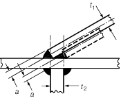
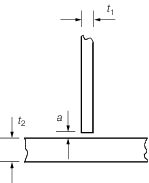
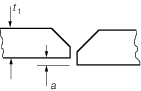
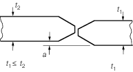
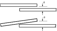
4.5 Structural misalignment and fit
4.5.2
Table 3.4.2 Structural misalignment and fit
(see continuation) defines the minimum limits
of accuracy required to be achieved in the various welded joint designs.
When these values are not achieved, the defects are to be discussed
and rectification agreed between the Builder and the Surveyor before
remedial action is taken.
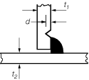
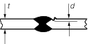
4.5.3 Limits for
weld undercut and remedial action to be taken depends on plate thickness
and are to be discussed and rectification agreed between the Builder
and the Surveyor prior to commencement of repairs.
4.6 Post-welding plate deformation
4.6.1 Post-welding
deformation of steel construction should be kept to a minimum.
4.6.3 Controlled
and localized heating of steel is not to exceed 900°c (red heat).Where
water cooling is employed the steel temperature is to be below 600°c
before any water is applied.
Table 3.4.1 Plate deformation limits
| Position
|
s/t
|
δp/s
|
| from 0,2L
R to 0,8L
R
|
≤ 80
>
80
|
1/100
1/75
|
| Remainder
|
all
|
1/50
|
where
|
L
R
|
= |
Rule length in m |
|
s |
= |
stiffener spacing, in mm |
|
t |
= |
plating thickness, in mm |
|
δp
|
= |
actual panel deflection, in mm |
|
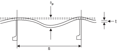
Figure 3.4.1 Measurement of plate deformation
4.6.4 With the assembly
of large blocks, careful attention should be paid to the areas in
way of lifting lugs. It is not unusual to find small fractures in
the vicinity of the weld area after removal of lugs. Where lugs are
removed, the dressing of the plate must be thorough and magnetic particle
or dye penetrant detection of the finished surface is good practice.
Repair of any cracks found must be carried out by qualified welders
under strict control.
4.6.5 Any unusual
incidents during construction, such as fracturing of plates, should
be noted and brought to the attention of the local Manager with a
view to a suitable report being made. It will be necessary to have
full information on the circumstances affecting such cases, such as
the position and extent of the fracture relative to adjacent structure
and welds, atmospheric temperature, details of joints, precise stage
and sequence of welding, type of electrode used, whether or not pre-heating
was used, grades of steel involved and any other factors considered
to have had a possible influence. Test details of affected plates
and proposals for remedial measures should also be reported. Where
doubt exists in establishing the source of such incidents, the assistance
of LR Headquarters may be sought.
4.7 Accessibility
4.7.1 Surveyors in
building yards should bear in mind the need for accessibility in a
vessel in service. Surveyors should ensure, as far as possible, that
access is adequate for future maintenance and surveys. In many cases,
the only reasonable sized access holes available have access restricted
by pipe runs.
Table 3.4.2 Structural misalignment and fit
(see continuation)
| Joint
|
Location
|
Multiple
defects
|
Isolated
defects
|
Remedial action
|
| Built section
flanges
|
All areas
|
a ≤ ± 0,015 x
|
a ≤ ± 0,03 x
|
|
Realign
|
|
| Flange
alignment
|
|
|
|
|
|
|
Primary
structure
|
-
|
a ≤ 0,03W
(max 6 mm)
|
a > 0,03W
|
Release over
50a
and realign
|
Secondary
structure
|
a ≤ 0,03W
max 6 mm)
|
a ≤ 0,04W
(max 8 mm)
|
a > 0,04W
|
Taper over 3a
|
|
|
|
|
a > 0,08W
|
Release over
5w
and realign
|
| Stiffener but
|
All areas
|
|
|
|
|
|
For angle or
tee
longitudinal
a ≤ 0,2t
1
|
For angle or
tee
longitudinal
a ≤ 0,2t
1
|
a > 0,2t
1
|
Reject
|
For offset
bulb
longitudinal
a ≤ 0,2t
2
|
For offset
bulb
longitudinal
a ≤ 0,2t
2
|
a > 0,2t
2
|
Reject
|
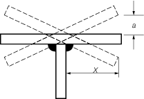
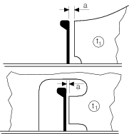
| Angled intersection
|
All
areas
|
-
|
a ≤ t
1/2
|
a > t
1/2
|
Realign
|
|
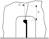
| Cruciform joint
|
|
|
|
|
|

|
Strength members
members
|
-
|
a ≤ t
2/3
|
a ≤ t
2/2
|
Increase weld
leg
length of welds by
10%
|
Other
members
|
-
|
a ≤ t
2/2
|
a > t
2/2
|
Realign
|
HT steel
joints
in
designated
critical
areas
|
-
|
b ≤ t
2/3
|
b > t
2/3
|
Realign
|
Table 3.4.3 Structural misalignment and fit (continued)
| Joint
|
Location
|
Multiple
defects
|
Isolated
defects
|
Remedial action
|
| Undercut
|
All areas
|
-
|
d ≤ 0,1t
1
(max 0,8 mm)
|
d > 0,1t
1
|
Repair by welding or
grinding
depends on thickness ‘t
1’
in
accordance with Ch 3, 2.3 Defects in steel products
|
|
| Undercut
|
All areas
|
-
|
d ≤ 0,1t
(max
0,8 mm)
|
d >
0,1t
|
As above
|
|
| Fillet weld
|
|
|
|
|
|
|
|
|
|
a ≤ 0,5t1
|
Increase weld leg length
by ‘a’
|
All areas
(continuous)
|
a ≤ 1,5 mm
|
a ≤ 0,25t
1
|
a ≤ t
1
|
Vee
material to +/–45°. Fit backing strip and weld. Remove backing
strip and complete weld.
|
| (max 16 mm)
|

|
|
a > t
1
|
Cut back 300mm and replace
|
All areas
(intermittent)
|
a ≤1,5 mm
|
a ≤ 0,25t
1
|
a ≤ 0,5t
1
(max 1,5 mm)
|
Increase weld lengths by 50%
|
a ≤ 0,5t
1
(max 5 mm)
|
Continuous weld
|
|
a > 0,5t
1
|
As for continuous weld above
|
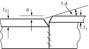
| Butt joint
|
|
|
|
|
|
|
Strength
members
|
-
|
a ≤ 0,15t
1
(max
3 mm)
|
a >
0,15t
1
|
Realign
|
| Others
|
a ≤ 0,15t
1
(max 3
mm)
|
a ≤
0,2 t
1
(max 3 mm)
|
a > 0,2t
1
|
Realign
|
| Butt weld
|
|
|
|
|
|
|
Strength
members
|
a ≤
0,15t
1
(max 3,0 mm)
|
a ≤ 0,15t
1
(max 3,0 mm)
|
a > 0,15t
1
|
Realign
|
| Other
|
a ≤ 0,2t
1
(max 3,0 mm
|
a ≤ 0,2t
1
(max
3,0 mm)
|
a >
0,2t
1
|
Realign
|
| Butt
joint repair
|
|
|
|
|
|
|
All areas
|
-
|
a in accordance with
weld
procedure
|
a ≤ t
1
|
Build
one side of butt until a in
accordance with weld
procedure
|
a > t
1
(max 3 mm)
|
Cut back 300 mm and fit
insert
plate
|
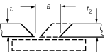
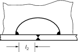
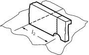
Table 3.4.4 Structural misalignment and fit
(conclusion)
| Joint
|
Location
|
Multiple
defects
|
Isolated
defects
|
Remedial
action
|
|
| Butt and fillet weld
|
|
|
|
|
|

|
All areas
|
-
|
l1 ≥ 40 mm
|
–
|
Adjust to
suit
|
| Butt and cutout
|
|
|
|
|
|
|
All areas
|
-
|
l 2 ≥ 20 mm
|
-
|
Adjust to suit
|
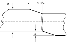
| Adjacent butts
|
|
|
|
|
|

|
All areas
|
l 1 ≥ 50 mm
|
l 1 ≥ 30 mm
|
l 1 < 30 mm
|
add insert
|
| Plate and stiffener butt
|
|
|
|
|
|
|
All areas
|
l 2 ≥ 20 mm
|
l 2 ≥ 15 mm
|
l 2 < 15 mm
|
Adjust to suit
|
| Lapped connection
|
|
|
|
|
|
|
All areas
|
a ≤ 1,0
|
a ≤ 2,0
|
a > 2
|
Increase weld leg length
by
actual ‘a’
|
|
|
|
|
a ≥ 5
|
Release and
realign
|
| Siffener connection
|
|
|
|
|
|
|
All areas
|
b ≤ 0,02a
|
|
b > 0,02a
|
Release and realign
|
| lug and bracket connection
|
|
|
|
a ≤ 0,5t
1
(max 5 mm)
|
Increase weld leg length by ‘a’
|
|
|
|
|
a ≤ t
1
|
Vee material to +/–45°. Fit backing strip and
weld. Remove backing strip and complete weld.
|
| All areas
|
a ≤ 2 mm
|
a ≤ 0,25t
1
|
(max 16 mm)
|

|
|
|
|
|
a > t
1
|
Cut back 300 mm and replace
|
4.7.2 While attention
is drawn to the need for adequate access, Surveyors should also be
alert for additional or enlarged access holes which should not be
permitted in highly stressed areas and which are sometimes fitted
at a late stage in construction.
4.7.3 It should also
be borne in mind that the lack, or bad positioning, of ladders, walkways
and manholes may render access under service conditions extremely
difficult and dangerous. The Builder’s attention should be drawn
to these considerations. In this respect, National Regulations may
specify requirements for ladders, walkways and the minimum size of
access openings.
4.7.4 Where significant
proportions of the ship’s structure are removed for access,
the Builder’s calculations demonstrating the adequacy of the
remaining structure are to be submitted.
4.8 Departures from approved arrangements
4.8.1 It is the Surveyor’s
duty to be alert through all stages of work to ensure that any significant
modifications or departures from approved arrangements are noted promptly
and dealt with as necessary. It should be clearly understood that
deviations from the Rule requirements or approved plans, other than
those of a minor nature and not affecting the structural strength
of the ship, must not be accepted by the local Surveyor without consultation
with the Surveyor-in-charge of the local LR office who, if he considers
it appropriate, should submit plans showing the proposed arrangements
to the relevant Plan Approval Office.
4.8.2 Large openings
not indicated on approved plans are not to be arranged in decks without
prior consultation with the Plan Approval Office. Small openings for
access, ventilation, etc. may be accepted by the Surveyor who should
ensure that they are adequately framed, and when necessary suitably
compensated. Requirements for compensation of loss of deck plating,
transverse cross-sectional area, and/or edge reinforcement are stated
in the appropriate sections of the Rules.
4.8.3 The corners
of openings, welded attachments to the sheerstrake (e.g. at bulwark
recesses) and small openings cut in decks may not be detailed on approved
plans and special attention should be paid to such areas to ensure
that no discontinuity, which may produce a notch effect, is built
into the structure. Adequate rounding of the corners of openings,
with grinding if necessary to a smooth finish, must be ensured to
eliminate possible sources of failure in service. The endings of bulwarks
should be smoothly tapered without any notch.
4.8.4 Defective welding
of seams or butts, with incomplete penetration, omission of sealing
runs or craters can result in fractures. When modifications have been
made which result in openings having to be closed by welded inserts,
particular attention should be paid to welding, with suitable NDE.
4.9 Marking of ship’s name, draught marks, etc. by welding
4.9.1 Draught marks
and paint lines are often permanently indicated on ships’ sides
by means of beads of welding or by letters or marks cut from steel
plate and welded to the sides.
4.9.2 Lettering on
the sheerstrake should be kept below a line 0,1D below
the deck, where D is the depth at side. Great care should
be taken in the application of the welding, which should be carried
out by qualified welders. Substantial runs should be laid continuously,
using large diameter low hydrogen electrodes and avoiding light runs
as these are more likely to promote fractures. Sharp corners in the
letters should be avoided and where the welding crosses a welded butt
or seam, the latter should be ground flat for about 75 mm each side
of the line of the weld bead before it is laid.
4.9.3 On steel of
Grade D or E or on higher tensile steel, low hydrogen electrodes should
be used of a grade suitable for the steel. In the case of higher tensile
steel, pre-heating to about 100°C should be adopted.
4.9.4 In the case
of midship draught marks which are located on special quality steel
similar precautions should be observed.
4.10 Acceptance testing on completion
4.10.2 Suitable
schedules should be produced. It is good practice to first test those
tanks which contain supporting structure, so that inspection is made
on the smooth, unencumbered sides of the bulkheads.
4.10.3 During testing,
the Surveyor should be accompanied by a responsible person and should
be satisfied that adequate lighting is available. Particular care
is to be exercised if testing is carried out during trial trips.
4.10.4 Attention
is drawn to the fact that internal boundary welds made by other than
automatic processes should not be coated before leak testing.
4.11 Launching
4.11.1 Surveyors
will normally attend and witness the launch of every vessel being
built under Special Survey. This applies also when ships are built
in a dry-dock and launching is only a symbolic inlet of water from
dock gates.
4.11.2 Under traditional
launching methods, if anything occurs which may affect the ship’s
structure, the Surveyor should carry out a careful examination for
possible damage, as circumstances require. Close attention should
be paid to examination of bottom structure in way of launching ways,
etc. after launch. Should any damage be found which is not satisfactorily
repaired before the completion of the ship, a suitable Condition of
Class should be imposed.
4.11.3 Anchors and
chain cables supplied for the equipment of a ship in service should
not be used as launching drags.
4.12 Fitting out
4.12.1 In the period
during fitting out of the accommodation, installation of electrical
conduits or ventilation trunking, particular vigilance is necessary
in order to ensure that the strength of structural members is not
impaired by the cutting. Where structural members are cut, adequate
reinforcement should be made of girders, brackets, stiffeners, etc.
It is also important that watertight or fire rated bulkheads are maintained
intact. Any doubts should be referred to the relevant Plan Approval
Office.
4.13 Completion of work after leaving the Builder’s yard
4.13.1 When a vessel
proceeds from the building port to another district for installation
of machinery, completion or dry-docking, it is required that the work
done be inspected and appropriately tested. This may be done by the
Surveyors in the port to which the ship has gone or, if the completing
port is within easy access of the building port, by the Surveyors
under whose inspection the ship was built. This is a matter for arrangement
between the LR offices concerned, the Owners and the Builders.
4.13.2 When the
survey is to be completed by the Surveyors at the port to which the
ship has gone, the building port Surveyors are to forward to them
all necessary plans and a detailed list of items outstanding for completion
of the ship and survey. Both offices are to make and agree arrangements
for the completion of reports and provision of certificates.
|