
Section
2 Hull strengthening requirements
2.1 Application
2.1.1 Where
the notation 'Ice Class 1AS, 1A, 1B, or 1C'
as specified in Vol 1, Pt 1, Ch 2, 3.10 Other notations 3.10.15 is desired, the ship is to comply with the requirements
of this Section, in addition to those for sea-going service, so far
as they are applicable.
2.1.2 The
vertical extent of the ice strengthening is related to the ice light
and ice load waterlines, which are defined in Vol 3, Pt 1, Ch 1, 2.2 Definitions . The maximum and minimum Ice Class
draughts at both the fore and aft ends will be stated on the Class
Certificate.
2.1.3 The
ballast capacity of the ship is to be sufficient to give adequate
propeller immersion in all ice navigating conditions without trimming
the ship in such a manner that the actual waterline at the bow is
below the ice light waterline.
2.1.4 Fresh-water
and sea-water ballast tanks, the tops of which are situated above
the minimum operating condition waterline and adjacent to the shell,
and which are intended to be used in ice and cold navigation conditions,
are to be provided with means to prevent freezing. It is to be demonstrated
that such means protect against the following:
-
Hull structural
damage caused by tank contents being pumped from beneath a layer of
ice, thereby drawing a vacuum into the tank.
-
Hull structural
damage caused by ice expansion.
-
Tank internal piping
and other components being damaged by ice expansion or blockage by
ice.
-
Tank internal piping
and other components being mechanically damaged by falling pieces
of ice.
Heating coils are considered effective means for tanks entirely
above the waterline. Heating coils, continuous circulation, air bubbling
or alarms and instrumentation are considered effective means for tanks
partially below the waterline. Alternatively, submission of documentary
evidence of service experience, testing, calculations or a combination
thereof may be used to demonstrate that the above hazards have been
mitigated.
2.1.5 The
requirements of this Section are formulated for both transverse and
longitudinal framing systems but it is recommended that, whenever
practicable, transverse framing is selected.
2.1.6 The
requirements of this Section assume that when approaching ice infested
waters the ship’s speed will be reduced appropriately. The vertical
extent of ice strengthening for ships intended to operate at speeds
exceeding 15 knots in areas containing isolated ice floes will be
specially considered.
2.1.7 An icebreaking
ship is to have a hull form at the fore end adapted to break ice effectively.
It is recommended that bulbous bows are not fitted to Ice Class 1AS ships.
2.1.8 The
stern of an icebreaking ship is to have a form such that broken ice
is effectively displaced.
2.1.9 Where
it is desired to make provision for short tow operations, the bow
area is to be suitably reinforced. Similarly, ice breakers may require
local reinforcement in way of the stern fork.
2.2 Definitions
2.2.1 The Ice
Deep Waterline corresponds to the Deep Draught Waterline. Where
specially requested, an Ice Deep Waterline may be specified which
differs from the foregoing, but corresponds to the deepest condition
in which the ship is expected to navigate in ice. See
Vol 1, Pt 3, Ch 1, 5.3 Margins for margins.
2.2.2 The Ice Light Waterline is that
corresponding to the lightest condition in which the ship is expected to navigate in
ice. However, it is recommended that the minimum draught at the fore end is not to be
less than:

where
2.2.3 The
Ice Deep Waterline and the Ice Light Waterline are to be indicated
on the plans.
2.2.5 The Forward
Region extends from the stem to aft of the forward borderline
of the flat side of the hull by a distance equal to the greater of
0,04L
R or 5 m for ice classes 1AS and 1A, or the greater of 0,02L
R or 2 m
for ice classes 1B and 1C. Where no clear
forward borderline of the flat side of the hull is discernible, the
aft boundary of the forward region is to be taken 0,4L
R aft of the forward perpendicular.
2.2.6
Forefoot
Region 1 is the area below the main ice belt zone extending
from the stem, or the fore end of the bulb where a bulbous bow is
fitted, to a position five frame spaces aft of the point of intersection
between the level keel line and the raked stem.
2.2.7
Forefoot
Region 2 is the area below the main ice belt extending from
the aft boundary of Forefoot Region 1 to the aft boundary of the forward
region and encompasses both side and bottom shell plating.
2.2.8 The Shoulder
Region is a part of the main ice belt zone in the forward region
and extends from the aft boundary of the forward region to forward
of the forward borderline of the flat side of the hull by a distance
of 0,04L
R for ice classes 1AS and 1A or 0,02L
R for ice classes 1B and 1C. Where no clear forward borderline of the flat side of the
hull is discernible, the forward boundary of the shoulder region is
to be taken 0,32L
R aft of the forward perpendicular
for ice classes 1AS and 1A or 0,36L
R aft of the forward perpendicular for ice classes 1B and 1C. The extent of the shoulder region forward of its aft boundary
is not to be taken as less than 10 m for ice classes 1AS and 1A or 4 m for ice classes 1B and 1C.
2.2.9 The Midship
Region extends from the aft boundary of the forward region
to aft of the aft borderline of the flat side of the hull by a distance
equal to the greater of 0,04L
R or 5 m for
ice classes 1AS and 1A or the greater of
0,02L
R or 2 m for ice classes 1B and 1C. Where no clear aft borderline of the flat side of the hull
is discernible, the aft boundary of the midship region is to be taken
0,2L
R forward of the aft perpendicular.
2.2.10 The Aft Region extends from the aft boundary of the midship region
to the stern.
2.2.11
Displacement ∆ is the displacement, in tonnes, at the Ice Deep Waterline
when floating in water having a relative density of 1,0.
2.2.12
Shaft
power, P
0 , is the maximum propulsion
shaft power, in kW, for which the machinery is to be classed.
2.3 Powering of ice strengthened ships
2.3.2 Ice
strengthened ships which are to be considered to have an independent
icebreaking capability are to be able to develop sufficient thrust
to permit continuous mode icebreaking at a speed of at least five
knots in ice having a thickness equal to the nominal value specified
in Vol 1, Pt 1, Ch 2, 3.10 Other notations 3.10.15 for
the desired Ice Class and a snow cover of at least 0,3 m.
2.3.3 The
requirements of Vol 3, Pt 1, Ch 1, 2.4 Shell plating are
formulated on the assumption that the shaft power necessary to provide
an independent icebreaking capability as described in Vol 3, Pt 1, Ch 1, 2.3 Powering of ice strengthened ships 2.3.2 can be determined by the equation:
|
P
1
|
= |
0,736C
1
C
2
C
3
C
4 [240B
h (1
+ h + 0,035v2) +70S
c
 )] )]
|
where
|
B
|
= |
breadth
as defined in Vol 1, Pt 3, Ch 1, 5 Definitions
|
|
C
1
|
= |
 ,
but is not to be taken as less than 1,0 ,
but is not to be taken as less than 1,0 |
|
C
2
|
= |
0,9 if the ship is fitted with a controllable pitch propeller,
otherwise 1,0 |
|
C
3
|
= |
0,9 if the rake of the stem is 45º or less, otherwise 1,0.
The product C
2
C
3 is
not to be taken as less than 0,85
|
|
C
4
|
= |
1,1 if the ship is fitted with a bulbous bow, otherwise 1,0 |
|
h
|
= |
ice
thickness as defined in Vol 3, Pt 1, Ch 1, 2.2 Definitions 2.2.2
|
|
S
c
|
= |
depth of snow cover |
|
v
|
= |
ship
speed, in knots, when breaking ice of thickness h
|
2.3.4 The
ice strengthening requirements of Vol 3, Pt 1, Ch 1, 2.4 Shell plating include a power-displacement correction factor, γ,
which is to be determined as follows:
-
Forward region
|
γ |
= |
0,653 +
3,217  x 10-5 x 10⁻⁵
|
|
or γ |
= |
0,876
+ 9,908  × 10-6 × 10⁻⁶
|
|
or γ |
= |
1,0 whichever
is the least |
where P
0 and Δ are
as defined in Vol 3, Pt 1, Ch 1, 2.2 Definitions .
For ships assigned ice classes 1AS and 1A, in which the installed shaft power P
0 exceeds
the shaft power P
1 determined in accordance
with Vol 3, Pt 1, Ch 1, 2.3 Powering of ice strengthened ships 2.3.3 when the ship speed
is taken as five knots, the ice thickness, h, as defined
in Vol 1, Pt 1, Ch 2, 3.10 Other notations 3.10.15 and
the snow cover S
c is taken as 0,3 m, γ
for the forward region is to be multiplied by the following factor:
-
for shell plating
1 + 0,1
-
for framing,
stringers and web frames
1 + 0,05
but γ need not be taken greater than 1,1.
-
Midship and aft
regions
|
γ |
= |
0,653 +
9,908 × 10-6 × 10-6
|
|
or |
= |
0,79, whichever
is the lesser. |
2.4 Shell plating
2.4.1 In way
of the main ice belt zone, the thickness of the shell plating is not
to be less than:
|
t
|
= |
As αp β γ + c mm + c mm
|
where
|
c
|
= |
corrosion-abrasion
increment to be taken as 2 mm for first-year ice classes, see
also
Vol 3, Pt 1, Ch 1, 2.4 Shell plating 2.4.3
|
|
s
|
= |
distance
to the adjacent main or intermediate frame, in mm |
|
A
|
= |
0,40
in association with transverse framing |
|
|
= |
0,41 in association
with longitudinal framing |
|
αp
|
= |
longitudinal
distribution factor, dependent on Ice Class and longitudinal position,
as given in Table 1.2.2 Longitudinal distribution
factor-shell plating
|
|
β |
= |
vertical distribution
factor, to be taken as 1,0 for all first-year ice classes |
|
γ |
= |
power-displacement
factor determined in accordance with Vol 3, Pt 1, Ch 1, 2.3 Powering of ice strengthened ships 2.3.4
|
|
σo
|
= |
specified
minimum yield stress of the steel, in N/mm2. For mild steel
the value 235 N/mm2 is to be used.
|
Table 1.2.2 Longitudinal distribution
factor-shell plating
| Ice Class
|
αp
|
| Forward
|
Midship
|
Aft
|
1AS
1A
1B
1C
|
1,00
0,98
0,93
0,86
|
0,95
0,86
0,71
0,53
|
0,85
0,73
0,57
0,38
|
2.4.2 Where
operation in first-year ice is an emergency feature as recognised
by Vol 1, Pt 1, Ch 2, 3.10 Other notations 3.10.15 with
a * annotated to the Ice Class notation, consideration will be given
to the use of fully plastic design criteria for the shell plating.
2.4.4 For
ice classes 1AS and 1A, where the hull form
includes a pronounced shoulder, the value of the corrosion-abrasion
increment in the shoulder region will be specially considered.
2.4.5 For
ice classes 1AS and 1A, the thickness of
shell plating is to be as follows:
-
In Forefoot Region
1 – not less than that determined in accordance with Vol 3, Pt 1, Ch 1, 2.4 Shell plating 2.4.1 for the main ice belt zone
in the forward region.
-
In Forefoot Region
2 – 2 mm greater than that required by Vol 1, Pt 6, Ch 3 Scantling Determination or Vol 1, Pt 7 Enhanced Structural Assessment (Provisional) for
ships with TLA notation.
-
For the forward
0,2L
R, the region 2 m above the main ice belt
zone in ships having an open water speed equal to and exceeding 17,5
knots (9 m/sec) – not less than that required in the ice belt
in the Midship Region.
2.4.6 Changes
in plating thicknesses in the longitudinal direction are to take place
gradually. Side scuttles are not to be situated in the ice belt.
2.4.7 If the
weather deck in any part of the ship is situated below the upper limit
of the ice belt, as may be the case of a raised-quarter decker, the
bulwark is to be reinforced to a standard required for the shell plating
in the main ice belt.
2.5 Transverse framing
2.5.1 The
increased requirements for transversely framed structures are normally
met by the addition of intermediate frames.
2.5.2 Ships
with shock enhanced notation transverse intermediate frames are not
to be fitted. The ice strengthening requirements are to be met by
the use of reduced main frame spacing.
2.5.3 The
section modulus of transverse main and intermediate frames (including
a width of attached plating equal to s), is to be determined
in accordance with the following formula:
|
Z
|
= |
Cs αt β γ2
 (3 (3 2 – h
2) K cm3
2 – h
2) K cm3
|
where
|
d
|
= |
distance,
in metres, measured along the frame from the lower span point to the
ice deep waterline or from the upper span point to the ice light waterline,
whichever is the lesser. In no case is this distance to be taken greater
than 
|
|
h
|
= |
nominal
ice thickness, in metres, for the Ice Class as defined in Vol 1, Pt 1, Ch 2, 3.10 Other notations 3.10.15
|
s, β, γ and σo are as
defined in Vol 3, Pt 1, Ch 1, 2.4 Shell plating 2.4.1
|
K
|
= |
 but is not to be taken greater than 1,0 nor less than
0,3. If the lower span point is above the ice load waterline or the
upper span point is below the ice light waterline, then k is
to be taken as 0,3 but is not to be taken greater than 1,0 nor less than
0,3. If the lower span point is above the ice load waterline or the
upper span point is below the ice light waterline, then k is
to be taken as 0,3
|

|
= |
span, in metres, measured
along a chord at the side between the span points. For definitions
of span points, see
Vol 1, Pt 6, Ch 2, 2 Structural design. Where adjacent main and intermediate frames
have different end connections, resulting in different spans, a mean
value is to be used.
|
Table 1.2.3 Longitudinal distribution factor -
transverse framing
| Ice Class
|
αt
|
| Forward
|
Midship
|
Aft
|
1AS
1A
1B
1C
|
1,00
0,89
0,78
0,66
|
0,87
0,68
0,49
0,31
|
0,66
0,49
0,33
0,16
|
2.5.4 The inertia of transverse main and
intermediate frames including a width of attached plating equal to s is to be
determined in accordance with the following formula:

|
= |
4Z
 cm4 cm4
|
where
2.5.5 The
cross-sectional shear resisting area of transverse main and intermediate
frames is to be determined in accordance with the following formula:
|
A
|
= |
Cs αt β γ2
 K
s cm2
K
s cm2
|
where s, β, γ and σo are
as defined in Vol 3, Pt 1, Ch 1, 2.4 Shell plating 2.4.1
|
K
s
|
= |
0,5 if the upper span point is below the bottom edge of the
main ice belt zone or the lower span point is above the upper edge
of the main ice belt zone |
|
|
= |
1,0 for all other
cases |
2.5.6 Except
as allowed by Vol 3, Pt 1, Ch 1, 2.5 Transverse framing 2.5.7,
main and intermediate frames having scantlings as required by Vol 3, Pt 1, Ch 1, 2.5 Transverse framing 2.5.2 are to be continued
and bracketed to the first primary longitudinal member outside of
the minimum extent of ice framing given in Table 1.2.4 Minimum extent of ice
framing or to the top of floors
in ships having a single bottom. In the latter case intermediate frames
will require to be bracketed, or otherwise efficiently attached to
a gusset plate which is to be fitted at the level of top of floors.
The free edge of the horizontal gusset should be suitably supported.
In this context a primary longitudinal member is defined as either
a deck, inner bottom, margin plate, deep tank top or ice stringer
complying with the requirements of Vol 3, Pt 1, Ch 1, 2.8 Primary longitudinal members supporting transverse ice framing.
Table 1.2.4 Minimum extent of ice
framing
| Ice Class
|
Region
|
Minimum extent of ice framing
|
| Above Ice Deep
Waterline (mm)
|
Below Ice Light
Waterline (mm)
|
| 1AS
|
Forward
(stem to 0,3L
R)
|
1200
|
To double
bottom or top of floors or 1600 mm, whichever is the greater
|
| Forward
(abaft 0,3L
R) and Midship
|
1200
|
1600
|
| Aft
|
1200
|
1200
|
1A,
1B,
1C
|
Forward
(stem to 0,3L
R)
|
1000
|
1600
|
| Forward
(abaft 0,3L
R) and Midship
|
1000
|
1300
|
| Aft
|
1000
|
1000
|
2.5.7 If a
primary longitudinal member is fitted within 0,25 m inside a boundary
of the minimum extent of ice framing, intermediate frames may be terminated
at that member.
2.5.8 If a
primary longitudinal member is fitted within 1 m inside a boundary
of the minimum extent of ice framing, the intermediate frames may
be terminated at that boundary, provided that their ends are attached
to the adjacent main frames by a horizontal intercostal member having
the same scantlings as the intermediate frames.
2.5.9 If primary
longitudinal members are not fitted, or are located more than 1 m
inside a boundary of the minimum extent of ice framing, then the intermediate
frames may be either:
-
extended to a
primary longitudinal member or equivalent as defined by Vol 3, Pt 1, Ch 1, 2.5 Transverse framing 2.5.6.
-
terminated at
the boundary of minimum extent of ice framing and attached by a horizontal
intercostal member, having the same scantlings as the intermediate
frames, to the adjacent main frames. The scantlings of the main frames
are to be based on the spacing and span of the main frames. The inertia
of the intermediate frames is to be not less than 75 per cent of the
main frames.
2.5.10 Except
where provided for in Vol 3, Pt 1, Ch 1, 2.5 Transverse framing 2.5.7 and Vol 3, Pt 1, Ch 1, 2.5 Transverse framing 2.5.9, the ends of intermediate
frames are to be bracketed or otherwise efficiently attached to a
primary longitudinal member or are to be attached to adjacent brackets,
floors or main frames by a longitudinal flat bar. see also
Vol 3, Pt 1, Ch 1, 2.7 Framing - General requirements 2.7.5.
2.5.11 In
twin screw ships, three intermediate frames forward of, and three
aft of, the propeller blade tips are to extend to the double bottom.
2.6 Longitudinal framing
2.6.1 The
section modulus of longitudinal frames (including a width of attached
plating equal to s), is to be determined in accordance
with the following formula:
|
Z
|
= |
Cs αl β γ2
 2
2
 cm3 cm3
|
where
|
h
|
= |
ice
thickness as defined in Vol 3, Pt 1, Ch 1, 2.2 Definitions 2.2.2
|

|
= |
is as defined in Vol 3, Pt 1, Ch 1, 2.5 Transverse framing 2.5.3
|
|
s
|
= |
spacing,
in mm, of longitudinal frames but need not be taken as greater than
1000h
|
|
C
|
= |
16,6 |
|
αl
|
= |
longitudinal
distribution factor, dependent on Ice Class and longitudinal position,
as given in Table 1.2.5 Longitudinal distribution
factor-longitudinal framing
|
β, γ and σo are as defined in Vol 3, Pt 1, Ch 1, 2.4 Shell plating 2.4.1.
Table 1.2.5 Longitudinal distribution
factor-longitudinal framing
| Ice Class
|
α1
|
| Forward
|
Midship
|
Aft
|
1AS
1A
1B
1C
|
1,00
0,90
0,80
0,68
|
0,95
0,74
0,51
0,32
|
0,71
0,53
0,34
0,16
|
2.7 Framing - General requirements
2.7.1 The
web thickness of ice frames is not, in general, to be less than half
that of the attached shell plating with a minimum of 9 mm.
2.7.2 Where
a frame intersects a boundary between two of the hull regions defined
in Vol 3, Pt 1, Ch 1, 2.2 Definitions , the scantling requirements
applicable will be those for the forward region if the forward midship
boundary is intersected or for the midship region if the aft midship
boundary is intersected.
2.7.3 Main
and intermediate frames within the minimum extent of ice framing given
in Table 1.2.4 Minimum extent of ice
framing are to be efficiently
supported to prevent tripping, e.g. as shown in Figure 1.2.2 Framing support. The distance between
anti-tripping supports is not to exceed 1500 mm. The extent of anti-tripping
supports is to be as given in Table 1.2.6 Extent of anti-tripping
supports.
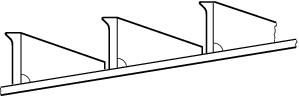
Figure 1.2.2 Framing support
Table 1.2.6 Extent of anti-tripping
supports
| Ice Class
|
Extent of
anti-tripping supports
|
1AS
1A
1B
1C
|
All regions
Forward and
midship region
Forward region
Forward
region
|
2.7.4 Ice
frames are to be attached to the shell plating by double continuous
welding and are not to be scalloped except at shell plating seams
or butts. However, in the case of the aft region for Ice Class 1A, 1B and 1C and the midship region for Ice Class 1B and 1C, consideration will be given to the
use of intermittent welding provided the requirements of Vol 1, Pt 6, Ch 6, 5.9 Intermittent and single sided fillet welding are complied
with.
2.7.5 Frames
are to be effectively attached to supporting structure by brackets.
In general, longitudinals are to be connected to both sides of cut-outs
in the webs of transverse structure.
2.7.7 Where
a bulkhead or deck is fitted instead of an ice strengthened frame,
the thickness of the bulkhead or deck adjacent to the shell is normally
to be that of the frame for a width sufficient to give an area equal
to the frame.
2.8 Primary longitudinal members supporting transverse ice framing
2.8.1 The
section modulus of ice stringers or of decks adjacent to hatchways,
including a width of attached plating determined in accordance with Vol 1, Pt 6, Ch 2, 2.3 Section properties and taken about
an axis parallel to the plating, is to be determined in accordance
with the following formula:
|
Z
|
= |
C αo β γ2
 2
2
 cm3 cm3
|
β, γ and σo are as defined in Vol 3, Pt 1, Ch 1, 2.4 Shell plating 2.4.1.
Table 1.2.7 Longitudinal distribution
factor-primary longitudinal members
| Ice Class
|
αo
|
| Forward
|
Midship
|
Aft
|
1AS
1A
1B
1C
|
1,00
0,87
0,78
0,68
|
0,98
0,75
0,64
0,53
|
0,89
0,64
0,51
0,37
|
2.8.3 Where
the span of a deck adjacent to a hatchway exceeds 10 times the width
of the deck strip the scantlings of the deck section may require special
consideration to ensure adequate stiffness.
2.8.4 The
webs of primary longitudinal members supporting transverse ice frames
are to be stiffened and connected to the main or intermediate frames
so that the distance, r, between such stiffening is not
to be greater than given according to the following formula:
|
r
|
= |
 mm mm
|
where
|
t
|
= |
thickness,
in mm, of the primary longitudinal member adjacent to the shell plating |
Other symbols are as defined in Vol 3, Pt 1, Ch 1, 2.8 Primary longitudinal members supporting transverse ice framing 2.8.1.
2.9 Web frames
2.9.1 The
section modulus of web frames supporting ice stringers or longitudinal
ice frames including a width of attached plating determined in accordance
with Vol 1, Pt 6, Ch 2, 2 Structural design and taken
about an axis parallel to the plating is to be determined in accordance
with the following formula:
|
Z
|
= |
Cs αo β γ2

 cm3 cm3
|
where
|
s
|
= |
spacing
of web frames, in metres |
β, γ and σo are as defined
in Vol 3, Pt 1, Ch 1, 2.4 Shell plating 2.4.1.
2.9.3 Ice
stringers are to be bracketed or otherwise efficiently attached to
the web frames or transverse bulkheads.
2.9.4 The
thickness of the web is generally not to be less than one per cent
of the web depth.
2.10 Stem
2.10.1 The
stem is to be made of rolled, cast or forged steel or of shaped steel
plates. A sharp edged stem, as shown in Figure 1.2.3 A sharp edged stem improves the manoeuvrability of the ship in ice.
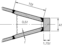
Figure 1.2.3 A sharp edged stem
2.10.2 The
section modulus of the stem in the fore and aft direction is not to
be less than determined in accordance with the following formula:
|
Z
|
= |
 cm3 cm3
|
where
β and γ are as defined in Vol 3, Pt 1, Ch 1, 2.4 Shell plating 2.4.1.
2.10.3 The
dimensions of a welded stem constructed as shown in Figure 1.2.3 A sharp edged stem are to be determined
in accordance with the following formula:
|
t
|
= |
31 mm mm
|
where
|
t
|
= |
thickness
of the side plates, in mm. |
2.10.4 The
plate thickness, t, of a shaped plate stem or a bulbous
bow is to be determined in accordance with the following formula:
|
t
|
= |
As αp β γ  + 2 mm + 2 mm
|
where
|
s
|
= |
the
distance, in mm, between horizontal webs diaphragm plates having a
thickness of at least 0,5t mm
|
αp, β, γ and σo are
as defined in Vol 3, Pt 1, Ch 1, 2.4 Shell plating 2.4.1.
2.10.5 The
reinforced stem is to extend from the keel plate to 750 mm above the
ice load waterline and is to be internally strengthened by floors,
brackets or webs having a thickness of at least 0,5t and
spaced not more than 600 mm apart.
2.10.6 In
bulbous bow constructions the extent of plating having the thickness, t, as specified in Vol 3, Pt 1, Ch 1, 2.10 Stem 2.10.4,
below the ice light waterline should be such as to cover that part
of the bulb forward of the vertical line originating at the intersection
of the ice light waterline and the stem contour at the centreline.
A suitably tapered transition piece should be arranged between the
reinforced stem plating and keel. However, in no case should the reinforced
stem plating extend vertically below the Ice Light Waterline for less
than 750 mm. The adjacent strake to the reinforced shaped stem plating
of the bulb should be in accordance with the requirements of Vol 3, Pt 1, Ch 1, 2.4 Shell plating 2.4.1.
2.10.7 Where
in the ice belt region the radius of the stem or bulb front plating
is large, one or more vertical stiffeners are to be fitted in order
to meet the section modulus requirement of Vol 3, Pt 1, Ch 1, 2.10 Stem 2.10.2. In addition, vertical ring
stiffening will be required for the bulb.
2.10.8 The
dimensions of the stem may be tapered to the requirements of Vol 1, Pt 6, Ch 3, 5.2 Plate keel at the upper
deck. The connections of the shell plating to the stem are to be flush.
2.10.9 For
towing purposes, a mooring pipe with an opening not less than 250
mm by 300 mm having inner surfaces at least 150 mm wide with a rounding
radius of not less than 100 mm is to be fitted in the bow bulwark
on the centreline. A bitt, or other convenient means of securing the
line, is to be dimensioned to withstand the breaking strength of the
ship’s towline.
2.11 Stern
2.11.1 Where
the screwshaft diameter exceeds the Rule diameter, the propeller post
is to be correspondingly strengthened. see
Vol 1, Pt 3, Ch 3, 2 Rudders.
2.11.2 A
transom stern is not normally to extend below the ice load waterline.
Where this cannot be avoided, the transom is to be kept as narrow
as possible and the scantlings of plating and stiffeners are to be
as required for the midship region.
2.12 Bossings and shaft struts
2.12.1 Shaftings
and sterntubes of ships with two or more propellers are generally
to be enclosed within plated bossings. If detached supporting struts
are necessary, their design, strengthening and attachment to the hull
will be specially considered.
2.13 Rudder and steering arrangements
2.13.1 Rudder posts, rudder horns, solepieces, rudder stocks and pintles are to be
dimensioned in accordance with Vol 1, Pt 3, Ch 3, 2 Rudders and Vol 1, Pt 3, Ch 3, 2.9 Rudder strength calculation as appropriate. Rudder scantlings are to be determined
in accordance with Vol 1, Pt 3, Ch 3, 2 Rudders using the basic stock diameter, δs. The
speed used in the calculations is to be the service speed or that given in Table 1.2.8 Minimum speeds, whichever is the greater. When used in
association with the speed given in Table 1.2.8 Minimum speeds, the hull form factor and rudder profile
coefficients are to be taken as 1,0.
Table 1.2.8 Minimum speeds
| Ice Class
|
Minimum speed, in knots
|
1AS
1A
1B
1C
|
20
18
16
14
|
2.13.2 For
double plate rudders, the minimum thickness of plating and horizontal
and vertical webs in the main ice belt zone is to be determined as
for shell plating in the aft region in accordance with Vol 3, Pt 1, Ch 1, 2.4 Shell plating 2.4.1. For the horizontal and vertical
webs the corrosion-abrasion increment, c, need not be
added.
2.13.3 For
ice classes 1AS and 1A, the rudder head
and the upper edge of the rudder are to be protected against ice pressure
by an ice knife, or equivalent.
2.13.4 Due
regard is to be paid to the method of securing the rudder in the centreline
position when backing into ice. Where possible, rudder stoppers working
on the blade or rudder head are to be fitted.
2.13.5 Where an ice class notation is included in the class of a ship, the nozzle
construction requirements as defined in Vol 1, Pt 3, Ch 3, 5 Fixed and steering nozzles, bow and stern thrust units, ducted propellers are to be upgraded to include
abrasion allowance as follows:
|
Ice Class
|
Thickness increment
|
1AS
1A
1B
1C
|
5
mm
4 mm
3 mm
2 mm
|
However, the thickness of the shroud
plating is not to be less than the shell plating for the aft region
as obtained from Vol 3, Pt 1, Ch 1, 2.4 Shell plating 2.4.1 taking
frame spacing s in the formula as 500 mm.
2.13.7 Nozzles
with articulated flaps will be subject to special consideration.
2.14 Direct calculations
2.14.1 If,
as an alternative to the requirements of Vol 3, Pt 1, Ch 1, 2.8 Primary longitudinal members supporting transverse ice framing and Vol 3, Pt 1, Ch 1, 2.9 Web frames, the scantlings
of primary longitudinal members and web frames are determined by direct
calculation, as permitted by Vol 1, Pt 3, Ch 1, 2 Direct calculations, then:
-
the applied ice
load may be taken as 775αo β γ2 kN
per metre of ship length evenly distributed over a depth equal to
the nominal ice thickness, h, for the Ice Class;
-
the scantlings
are to be suitable for the centre of the load depth to be located
at any height between the ice load waterline and the ice light waterline;
-
the scantlings
determined in association with Vol 3, Pt 1, Ch 1, 2.14 Direct calculations 2.14.1 and Vol 3, Pt 1, Ch 1, 2.14 Direct calculations 2.14.1.(b) are to be sufficient to ensure
that the von Mises-Hencky combined stress does not exceed 90 per cent
of the yield stress of the steel.
|