
Section
3 Machinery and engineering systems
3.1 General
3.1.1 Where
the notation, Ice Class 1AS, 1A, 1B or 1C is desired, the requirements of this Section, in addition
to those for open water service, are to be complied with so far as
they are applicable.
3.2 Symbols and definitions
3.2.1 The
symbols used in this Section are defined as follows:
|
B
|
= |
moulded
breadth of ship, in metres |
|
D
P
|
= |
diameter of the propeller, in metres |
|
H
M
|
= |
thickness of the brash ice in mid channel, in metres |
|
H
F
|
= |
thickness of the brash layer displaced by the bow, in metres |
|
L
WL
|
= |
length of ship at deep draught waterline, in metres |
|
T
ICE
|
= |
maximum ice class draught amidships, in metres, corresponding
to the deep draught waterline |
|
∆ |
= |
displacement,
in tonnes, on the maximum Ice Class draught amidships on the deep
draught waterline, see
Vol 3, Pt 1, Ch 1, 2.2 Definitions 2.2.1. This displacement need not be taken as greater than 80 000
tonnes
|
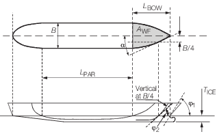
Figure 1.3.1 Definition of angles, areas and length
3.3 Engine output
3.3.1
Definition. The total engine output, P in Vol 3, Pt 1, Ch 1, 3.3 Engine output 3.3.2, is the maximum output the
propulsion machinery can continuously deliver to the propulsion system
with the propeller(s) operating at the revolutions per minute at the
maximum torque for which the system is to be classed. If the output
of the machinery is restricted by technical means or by any Regulations
applicable to the ship, P, shall be taken as the restricted
output.
3.3.2 Required
engine output:
-
For Ice
Class 1AS and 1A, the total engine output is not
to be less than determined by the following formula:
|
P
|
= |
K
E
 kW kW
|
where K
E is as shown in Table 1.3.1 Coefficient of propulsion,
K
E
R
CH, in N, is the resistance of the
ship in a channel with brash ice and a consolidated layer, using the
following equation:
|
R
CH
|
= |
C
1 + C
2 + 845
(H
F + H
M)2
 • •
|
(0,15 cos + sinψ • sinα) + 42L
PAR
H
F
2 + 825K
d + sinψ • sinα) + 42L
PAR
H
F
2 + 825K
d

where
|
Kd
|
= |

|
but is not to be taken as more than 20 or less than
5
|
H
F
|
= |
0,26 + 
|
|
H
M
|
= |
1,0 for Ice Classes 1A and 1AS
|
C
1 and C
2 take
into account a consolidated upper layer of the brash ice and can be
taken as zero for Ice Class 1A. For Ice Class 1AS:
|
C
1
|
= |
23 + (1 + 0,021 + (1 + 0,021 )(45,8B + 14,7L
BOW +
29BL
BOW) )(45,8B + 14,7L
BOW +
29BL
BOW)
|
|
C
2
|
= |
(1 + 0,063 )(1530 + 170B) +(400 + 480 )(1530 + 170B) +(400 + 480 ) ) 
|
|
Ψ |
= |
arctan 
|
-
For Ice
Class 1B and 1C, the total engine output is not
to be less than that determined by the following formula and in no
case less than 740 kW:
|
P
|
= |
f
1
f
2
f
3 ( f
4 ∆ + P
o ) kW
|
where
|
f
1
|
= |
1,0 for a fixed pitch propeller |
| = |
0,9 for a controllable pitch propeller |
|
f
2
|
= |
 + 0,675 but not more than 1,1 + 0,675 but not more than 1,1 |
|
f
2
|
= |
1,1 for a bulbous bow |
The product, f
1
f
2, is not to be taken as less than 0,85.
|
f
3
|
= |
 but not less than 1,0 but not less than 1,0
|
f
4 and P
0 are
to be taken as shown in Table 1.3.2 Values of f
4 and P
0
:
∆ is as defined in Vol 3, Pt 1, Ch 1, 3.2 Symbols and definitions.
Table 1.3.1 Coefficient of propulsion,
K
E
No. of
propellers
|
Propeller type
|
| Controllable pitch propeller
|
Fixed
pitch propeller
|
1
2
3
|
2,03
1,44
1,18
|
2,26
1,60
1,31
|
Table 1.3.2 Values of f
4 and P
0
|
|
1B
|
1C
|
1B
|
1C
|
| Δ < 30 000 t
|
Δ ≥ 30,000 t
|
|
f
4
|
0,22
|
0,18
|
0,13
|
0,11
|
|
P
0
|
370
|
0
|
3070
|
2100
|
3.4 Materials for shafting
3.4.1 All
components of the main propulsion system are to be of steel or other
approved ductile material.
3.4.2 For screwshafts in ships intended for the notation Ice Class 1AS or
1A and where the connection between the propeller and the screwshaft is by means
of a key, Charpy impact tests are to be made in accordance with the requirements of
Ch 5, 2.4 Mechanical tests.
3.5 Materials for propellers
3.5.1 Propellers
and propeller blades are to be of cast steel or copper alloys.
3.5.3 Spheroidal
cast iron load transmitting components of controllable-pitch mechanisms
are to be manufactured, tested and certified in accordance with the
requirements of Table 7.3.5 Mechanical properties: special
qualities in
Ch 7,3 of the Rules for Materials.
3.6 Determination of ice torque
3.6.1 Dimensions
of propellers, shafting and gearing are determined by formulae taking
into account the impact when a propeller blade hits ice. The ensuing
load is hereinafter defined by ice torque, M.
where
|
m
|
= |
21,10
for Ice Class 1AS
|
|
D
|
= |
diameter
of propeller, in metres. |
3.6.2 If the
propeller is not fully submerged when the ship is in ballast condition,
the ice torque for Ice Class 1A is to be used for Ice
Classes 1B and 1C.
3.7 Propeller blade sections
3.7.1 The
width, L, and thickness, T, of propeller
blade sections are to be determined so that:
-
at the radius
0,25D/2, for solid propellers
-
at radius 0,35D/2 for controllable pitch propellers
-
at the radius
0,6D/2
where
|
D
|
= |
diameter
of propeller, in metres |
|
L
|
= |
length
of the expanded cylindrical section of the blade, at the radius in
question, in mm |
|
P
r
|
= |
propeller pitch at the radius in question, for solid propellers,
in metres |
| = |
0,7 nominal pitch for controllable pitch propellers,
in metres |
|
R
|
= |
propeller
speed, in rev/min |
|
T
|
= |
the
corresponding maximum blade thickness, in mm |
|
σu
|
= |
specified
minimum tensile strength of the blade material, in N/mm2.
|
3.7.2 Where
the blade thickness derived from these formulae is less than the blade
thickness derived by Vol 2, Pt 4, Ch 1 Propellers,
the latter is to apply.
3.8 Propeller blade minimum tip thickness
3.9 Intermediate blade sections
3.10 Blade edge thickness
3.10.1 The
thickness of blade edges is to be not less than 50 per cent of the
derived tip thickness, t, measured at 1,25t from
edge. For controllable pitch propellers this applies only to the leading
edge.
3.11 Mechanisms for controllable pitch propellers
3.11.1 The
strength of mechanisms in the boss of a controllable pitch propeller
is to be 1,5 times that of the blade when a load is applied at the
radius 0,9D/2 in the weakest direction of the blade.
3.12 Keyless propellers
3.12.1 When
it is proposed to use keyless propellers, the fit of the propeller
boss to the screwshaft will be specially considered.
3.13 Screwshafts
3.13.1 The
diameter d
s at the aft bearing of the screwshaft
fitted in conjunction with a solid propeller is to be not less than:
|
d
s
|
= |
 mm mm |
where
|
L and T
|
= |
proposed width and thickness respectively of the propeller blade
section at 0,25D/2, in mm
|
|
σo
|
= |
specified
minimum yield stress of the material of the screwshaft, in N/mm2
|
|
σu
|
= |
specified
minimum tensile strength of the blade material, in N/mm2.
|
3.13.2 The
diameter, d
s at the aft bearing of the screwshaft
fitted in conjunction with a controllable pitch propeller is to be
not less than:
|
d
s
|
= |
 mm mm |
where
|
L and T
|
= |
proposed width and thickness respectively of the propeller blade
section at 0,35D/2, in mm.
|
3.13.3 Where
the screwshaft diameter as derived by Vol 3, Pt 1, Ch 1, 3.13 Screwshafts 3.13.1 or Vol 3, Pt 1, Ch 1, 3.13 Screwshafts 3.13.2 is less
than the diameter derived by Vol 2, Pt 3, Ch 2, 4.4 Screwshafts and tube shafts 4.4.3 or Vol 2, Pt 3, Ch 2, 4.4 Screwshafts and tube shafts 4.4.7 as
applicable the latter is to apply.
3.14 Intermediate and thrust shafts
3.15 Reduction gearing
3.15.1 Where
gearing is fitted between the engine and the propeller shafting, the
gearing is to be in accordance with Vol 2, Pt 3, Ch 1 Gearing, and is to be designed to transmit a torque, Y
i, determined by the following formula:
|
Y
i
|
= |
Y +  kN m kN m
|
where
|
u
|
= |
gear
ratio = 
|
 h
h
|
= |
mass moment
of inertia of machinery components rotating at higher speed |
 l
l
|
= |
mass moment
of inertia of machinery components rotating at lower speed, including
propeller with an addition of 30 per cent of entrained water |
( h and
h and  l are to be expressed in the same units)
|
Y
|
= |
9,55 . .
|
P and R are as defined
in Vol 2, Pt 1, Ch 3, 3.3 Calculations and specifications.
3.16 Starting arrangements
3.16.1 In addition to complying with the requirements of Vol 2, Pt 7, Ch 3, 12.11 Dead ship condition starting arrangements,Pt 10, Ch 1, 12.1 General, Vol 2, Pt 7, Ch 3, 12.12 Air receivers,
Vol 2, Pt 2, Ch 1, 8.5 Starting air pipe systems and safety fittings and Vol 2, Pt 2, Ch 1, 9.2 Electric starting where applicable, the capacity of the air compressors
is to be sufficient for charging the air receivers from atmospheric to full pressure in
half an hour for a ship with Ice Class 1AS where the propulsion engine has to be
reversed for going astern.
3.17 Sea inlet chests and cooling water systems
3.17.1 The
cooling water system is to be designed to ensure a supply of cooling
water when navigating in ice. For this purpose at least one cooling
water inlet chest is to be arranged as follows:
-
The sea inlet
chest is to be situated near the centreline of the ship and well aft
if possible.
-
As guidance for
design the volume of the chest shall be about one cubic metre for
every 750 kW engine output of the ship including the output of auxiliary
engines necessary for the ship’s service.
-
The chest shall
be of sufficient height to allow ice to accumulate above the inlet
pipe.
-
A recirculating
connection from the cooling water overboard discharge line, capable
of full capacity discharge, is to be led to the chest.
-
The net area
through the grating at the shell opening is to be not less than four
times the sectional area of the inlet pipe.
Where there are difficulties in meeting the requirements of Vol 3, Pt 1, Ch 1, 3.17 Sea inlet chests and cooling water systems 3.17.1.(b) and Vol 3, Pt 1, Ch 1, 3.17 Sea inlet chests and cooling water systems 3.17.1.(c) two smaller chests may be
arranged for alternating intake and discharge of cooling water. The
arrangement and situation otherwise shall be as above.
3.17.2 Heating
coils may be installed in the upper part of the chest or chests.
3.18 Fire pumps in motor ships
|