
Section
4 Loads on shell envelope
4.1 Pressures on the shell envelope
4.1.1 The design
pressures for the shell envelope including exposed decks are to include
the effects of combined static and dynamic load components. In addition,
the effects of impact or slamming loads are also to be considered,
but these are to be treated separately, see
Pt 5, Ch 2, 5 Impact loads.
4.2 Combined hydrostatic and hydrodynamic pressure on the shell plating
4.2.1 The total
pressure distribution, P
s, in kN/m2 acting
on the shell plating envelope due to hydrostatic and hydrodynamic
pressures is illustrated in Figure 2.4.1 Combined pressure distribution,
Ps
and
is to be taken as specified in Table 2.4.1 Combined pressure distribution,
Ps
.
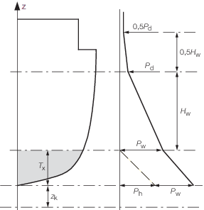
Figure 2.4.1 Combined pressure distribution,
Ps
Table 2.4.1 Combined pressure distribution,
Ps
Vertical
location
i.e. z value
|
Shell envelope
pressure, P
s
kN/m2
|
for z ≤ T
x +z
k
i.e. up to the operating waterline
|
P
h + P
w
|
| At z = T
x + z
k+ H
w
|
P
d
|
| At z ≥ T
x+ z
k + 1,5H
w
|
0,5P
d
|
| Symbols
|
| H
w is the nominal wave limit height, see
Pt 5, Ch 2, 4.4 Hydrodynamic wave pressure 4.4.4
|
| P
d is the weather deck pressure, see
Pt 5, Ch 2, 4.5 Pressure on weather and interior decks 4.5.1
|
| P
h is the hydrostatic pressure, see
Pt 5, Ch 2, 4.3 Hydrostatic pressure on the shell plating
|
| P
w is the hydrodynamic wave pressure, see
Pt 5, Ch 2, 4.4 Hydrodynamic wave pressure
|
| P
h and P
w are to be derived at the appropriate vertical position,
z
|
| T
x, z and z
k are defined in Pt 5, Ch 2, 2.2 Symbols
|
Note Pressure values at other z values are to be
derived by interpolation.
|
4.3 Hydrostatic pressure on the shell plating
4.3.1 The pressure, P
h, acting on the shell plating up to the operating
waterline due to hydrostatic pressure is to be taken as:
where
T
x, z and z
k are defined in Pt 5, Ch 2, 2.2 Symbols.
4.4 Hydrodynamic wave pressure
4.4.3 The distribution
of hydrodynamic pressure up to the operating waterline P
p, is to be taken as:
where
|
H
pm
|
= |

|
| = |
but not less than 
|
x
wI and L
WL are
defined in Pt 5, Ch 2, 3.1 Relative vertical motion.
4.5 Pressure on weather and interior decks
4.5.2 The pressure acting on weather and interior decks, Pwh, in
the displacement mode is to be taken as:
where
|
fL
|
= |
the location factor for weather decks |
|
|
= |
1,0 from aft end to 0,88LR
|
|
|
= |
1,25 from 0,88LR to 0,925L
R
|
|
|
= |
1,50 from 0,925LR to forward end |
|
fL
|
= |
1,0 for interior decks |
|
E
|
= |
 for exposed decks but need not be taken greater than 3
kN/m2 for exposed decks but need not be taken greater than 3
kN/m2
|
|
E
|
= |
0,0 for interior decks and superstructure decks aft of the forward
quarter |
|
Γ |
= |
Taylor Quotient
as defined in Pt 5, Ch 2, 2.1 Parameters to be used for the determination of load and design criteria 2.1.17, and
|
|
Δ |
= |
the displacement
as defined in Pt 5, Ch 2, 2.2 Symbols
|
LWL is as defined in Pt 5, Ch 2, 2.1 Parameters to be used for the determination of load and design criteria 2.1.19.
4.5.3 The pressure
acting on weather and interior decks, P
w⋉,
in the non-displacement mode is to be taken as:
where f
L and E are
as defined in Pt 5, Ch 2, 4.5 Pressure on weather and interior decks 4.5.2, and a
v is as defined in Pt 5, Ch 2, 3 Motion response.
-
av is not to be taken less than 1,0, but need not be taken greater
than 4,0 for weather decks.
-
av need not be taken greater than 1,0 for interior decks.
LWL is as defined in Pt 5, Ch 2, 2.1 Parameters to be used for the determination of load and design criteria 2.1.19.
|