
Section
2 Hull girder load criteria for mono-hull craft
2.1 General
2.2 Vertical wave bending moments
2.2.1 For all
craft except patrol craft in Service Group G6, the minimum value of
vertical wave bending moment, M
W at any position
along the craft is to be taken as follows:
where
|
Ff
|
= |
–1,1 for sagging (negative) moment |
| = |
1,9C
b/(C
b + 0,7) for hogging (positive) moment
|
|
Df
|
= |
the longitudinal distribution factor |
| = |
0 at aft end of L
R
|
| = |
1,0 between 0,4L
R and
0,65L
R
|
| = |
0 at forward end of L
R
|
Intermediate values of Df are to be determined by linear
interpolation
|
Mo
|
= |
0,1L
f
Gf
LR
2B (C
b + 0,7) kN m |
|
Lf
|
= |
0,0412LR + 4,0, for LR < 90 m |
| = |
10,75 – (3 – 0,01LR )1,5 for
LR ≥ 90 m |
2.2.2 For patrol craft in Service Group G6, the minimum value of vertical wave
bending moment, MW, at any position along the ship may be taken as
follows:
where
Ff is the hogging, FfH, or sagging, F
fS, correction factor based on the amount of bow flare, stern flare, length
and effective buoyancy of the aft end of the craft above the waterline. F
fS is the sagging (negative) moment correction factor and is to be taken as:
|
FfS
|
= |
–1,10RA
0,3 for values of RA ≥ 1,0 |
|
FfS
|
= |
–1,10 for values of RA < 1,0 |
RA is an area ratio factor, see
Pt 5, Ch 5, 2.2 Vertical wave bending moments 2.2.3
An
area ratio value of 1,0 results in a sagging correction factor of
–1,10
FfH is the hogging (positive) moment correction factor and is to be
taken as
|
Df
|
= |
the longitudinal distribution factor |
| = |
0 at aft end of LR
|
| = |
1,0 between 0,4LR and 0,65LR
|
| = |
0 at forward end of LR
|
Intermediate values of Df are to be determined by linear
interpolation
|
Mo
|
= |
0,1Lf
LR
2BWL (Cb + 0,7) kNm |
|
Lf
|
= |
0,0412LR + 4,0, for LR < 90 m |
| = |
10,75 – (3 – 0,01LR )1,5 for
LR ≥ 90 m |
|
BWL
|
= |
maximum breadth at the design waterline, in metres |
| = |
Cb to be taken not less than 0,60. |
2.2.3 The area ratio factor, RA, for the combined stern and bow
shape is to be derived as follows:
where
ABF is the bow flare area, in m2, see
Pt 5, Ch 5, 2.2 Vertical wave bending moments 2.2.4
ASF is the stern flare area, in m2, see
Pt 5, Ch 5, 2.2 Vertical wave bending moments 2.2.5.
2.2.4 The bow flare area, ABF, is illustrated in Figure 5.2.1 Derivation of bow and stern flare areas and may be derived as follows:
where
|
AUB
|
= |
half the water plane area at a waterline of TC,U of
the bow region of the hull forward of 0,8LR from the
AP. |
|
ALB
|
= |
half the water plane area at the design waterline of the bow region
of the hull forward of 0,8LR from the AP. |
Note the AP is to be taken at the aft end of the Rule length, L
R. The design waterline is to be taken at T, see
Pt 3, Ch 1 General Regulations. Alternatively
the following formula may be used:
where
|
b0
|
= |
projection of TC,U waterline outboard of the
design waterline at the FP, in metres, see
Figure 5.2.1 Derivation of bow and stern flare areas
|
|
b1
|
= |
projection of T
C,U waterline outboard of the design waterline at
0,9LR from the AP, in metres |
|
b2
|
= |
projection of TC,U waterline outboard of the design
waterline at 0,8LR from the AP, in metres |
|
a
|
= |
projection of TC,U waterline forward of the FP, in
metres |
T
C,U is a waterline taken Lf /2 m above the design waterline
L
f is given in Pt 5, Ch 5, 2.2 Vertical wave bending moments 2.2.2.
For ships with large bow flare angles above the TC,U
waterline the bow flare area may need to be specially considered.
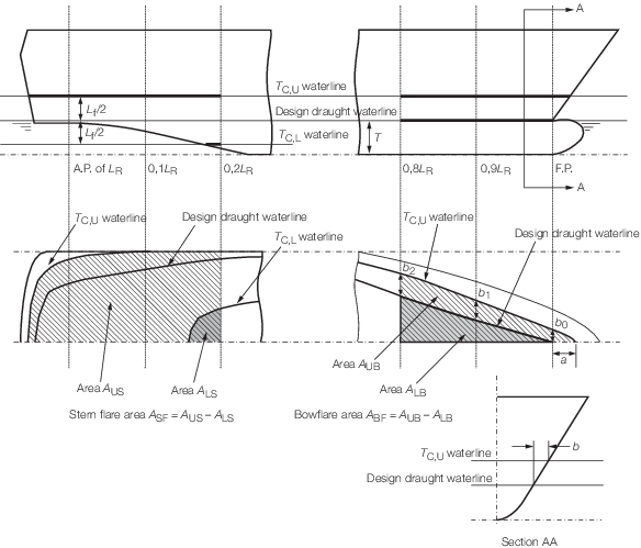
Figure 5.2.1 Derivation of bow and stern flare areas
2.2.5 The stern flare area, ASF, is illustrated in Figure 5.2.1 Derivation of bow and stern flare areas and is to be derived as follows:
where
|
AUS
|
= |
half the water plane area at a waterline of TC,U of
the stern region of the hull from aft to 0,2LR forward of the AP |
|
ALS
|
= |
half the water plane area at a waterline of TC,L
of the stern region of the hull from aft to 0,2LR forward of the
AP |
TC,L is a waterline taken Lf/2 m below the design
waterline
Lf is given in Pt 5, Ch 5, 2.2 Vertical wave bending moments 2.2.2.
For craft with tumblehome in the stern region, the maximum breadth at any
waterline less than TC,U is to be used in the calculation of
AUS. The effects of appendages including bossings are to be ignored
in the calculation of ALS.
2.2.6 The sagging correction factor, FfS , in the vertical wave
bending moment formulation in Pt 5, Ch 5, 2.2 Vertical wave bending moments 2.2.2 may be derived by direct calculation methods.
Appropriate direct calculation methods may include a combination of long term ship
motion analysis, non linear ship motion analysis and static balance on a wave crest or
trough.
2.3 Still water bending moments
2.3.1 The still
water bending moment, M
S, hogging and sagging
is the maximum moment calculated from the loading conditions.
2.3.2 Still water
bending moments are to be calculated along the craft length. For these
calculations, downward loads are to be taken as positive values and
are to be integrated in the forward direction from the aft end of L
R. Hogging bending moments are positive.
2.4 Wave shear force
2.4.1 The wave
shear force, Q
W, at any position along the
craft is given by:
where K
f is to be taken as
follows:
-
Positive shear force:
|
K
f
|
= |
0 at aft end of L
R
|
|
|
= |
1,589C
b/(C
b + 0,7) between 0,2L
R and 0,3L
R from aft end of L
R
|
|
|
= |
0,7 between 0,4L
R and 0,6L
R from aft end
of L
R
|
|
|
= |
1,0 between 0,7L
R and 0,85L
R from aft end
of L
R
|
|
|
= |
0 at forward end
of L
R
|
-
Negative shear force:
|
K
f
|
= |
0 at aft end of L
R
|
|
|
= |
- 0,92 between
0,2L
R and 0,3L
R from
aft end of L
R
|
|
|
= |
- 0,7 between 0,4L
R and 0,6L
R from aft end
of L
R
|
|
|
= |
- 1,727C
b/(C
b + 0,7) between 0,7L
R and 0,85L
R from aft end of L
R
|
|
|
= |
0 at forward end
of L
R
|
Intermediate values to be determined by linear interpolation.
M
o, C
b are as
defined in Pt 5, Ch 5, 2.2 Vertical wave bending moments 2.2.1 and Pt 5, Ch 5, 2.2 Vertical wave bending moments 2.2.2.
2.5 Still water shear force
2.5.1 The still
water shear force, Q
s, at each transverse
section along the hull is to be taken as the maximum positive and
negative value found from the longitudinal strength calculations.
2.5.2 Still water
shear forces are to be calculated at each section along the craft
length. For these calculations, downward loads are to be taken as
positive values and are to be integrated in a forward direction from
the aft end of L
R. The shear force is positive
when the algebraic sum of all vertical forces aft of the section is
positive.
2.5.3 The actual
shear force obtained from the longitudinal strength calculations may
be corrected for the effect of local forces at the transverse bulkhead,
if applicable.
2.6 Dynamic bending moments and associated shear forces
2.6.1 The dynamic
bending moments, including wave and still water effects, specified
here are applicable to all non-displacement mono-hull craft as defined
in Pt 1, Ch 2, 2.2 Definitions 2.2.14.
2.6.2 The dynamic
bending moment, due to slamming effects at amidships, is to be calculated
using the following expression:
where
|
|MD|
|
= |
is
taken to be the absolute value of the function, irrespective of signs |
|
M
D
|
= |
51ΔL
R(16a
v -
4a
b - 17a
s - 5) 10-3 kNm
|
|
Δ |
= |
displacement,
in tonnes, as defined in Pt 5, Ch 2, 2.2 Symbols 2.2.2
|
|
F
f
|
= |
- 1,0 for sagging (negative) moment |
|
|
= |
1,0 for hogging
(positive) moment |
|
D
f
|
= |
0 at aft end of L
R
|
|
|
= |
1,0 between 0,4L
R and 0,65L
R from aft
|
|
|
= |
0 at forward end
of L
R
|
|
a
v
|
= |
vertical acceleration at the LCG, in terms of g,
as defined in Pt 5, Ch 2, 3.2 Vertical acceleration 3.2.4, see
also
Pt 5, Ch 5, 1.1 Introduction 1.1.6
|
|
a
b
|
= |
vertical acceleration at forward end of L
R,
in terms of g
|
|
a
s
|
= |
vertical acceleration at aft end of L
R,
in terms of g
|
If the values of a
b and a
s are unknown, the distributions given in Pt 5, Ch 2, 3.2 Vertical acceleration 3.2.7 are applicable.
|