3.5.2 Checkpoints examined at the pre-fabrication stage are to include ultrasonic
testing on examples of the stop/start points of automatic welding and magnetic particle
inspections of weld ends.
3.5.4 Alternative proposals to Table 2.3.1 Non-destructive examinations of
welds will be considered
on a case by case basis for example, implementing a statistical approach based on
historical data and current trends, or implementing an enhanced quality assurance
process scheme.
Table 2.3.1 Non-destructive examinations of
welds
| Volumetric non-destructive examinations - Recommended extent of
testing
|
| Item
|
Location
|
Checkpoints, see
Notes 1,2 and 4 (these are common to all listed item locations)
|
| Intersections of butt and seams of
fabrication and section welds
|
Throughout:
- hull envelope
- longitudinal and transverse bulkheads
- inner bottom and hopper bottom
|
Checkpoints shall be taken at these
locations; the summation of checkpoint lengths examined at intersections is
to be 0,2L, where L is the overall length of the ship in
metres.
|
| Butt welds in plating
|
Throughout
|
1 m in 100 m, see Note
3
|
| Seam welds in plating
|
Throughout
|
1 m in 200 m, see Note
3
|
| Butts in longitudinals
|
Hull envelope within 0,4L
amidships
|
1 in 40 welds
|
|
|
Hull envelope outside 0,4L
amidships
|
1 in 30 welds
|
| Bilge keel butts
|
Throughout
|
1 in 40 welds
|
| Structural items when made with full
penetration welding as follows:
|
Throughout
|
1 m in 60 m
|
- connection of stool and bulkhead to lower stool shelf
plating
- vertical corrugations to an inner bottom
- hopper knuckles
- sheerstrake to deck stringer
- hatchways coaming to deck
|
|
|
Note
1. The length of each checkpoint is to be
between 0,3m and 0,5m, where the length of weld permits.
Note
3. Checkpoints in butt welds and seam
welds are in addition to those at intersections.
Note
4. The NDE checkpoint locations are not
to be indicated on the blocks prior to the welding taking place, nor
is any special treatment to be given at these locations.
|
3.5.5 Any checkpoint which contains a rejectable weld discontinuity shall be repaired, as
appropriate, and retested. Furthermore, volumetric NDE shall be increased by an
additional one checkpoint for each checkpoint failure, to be chosen at random by the
Surveyor. This additional checkpoint is supplementary to the repaired/retested location.
3.5.6 Systematic defects or repetitive defects shall be investigated, rectified,
and retested where appropriate. The extent of NDE checkpoints shall be increased in way
of the areas, weld types or intersections, where the systematic or repeated defects are
observed, by an additional 50 per cent of the affected item (listed in Item column of
Table 2.3.1 Non-destructive examinations of
welds, to determine the
weld quality.
3.5.7 If there is evidence to suggest the overall welding quality is not of a satisfactory
nature, then a further NDE checkpoint regime, and enhanced quality assurance process,
shall be applied. The fabricator shall present to the Surveyor the additional measures
and regime to be implemented.
3.5.9 Isolated gas pores, slag inclusions, or metallic inclusions shall not be
considered as systematic defects, however, they must be assessed individually with
respect to the applicable acceptance criteria within LR Rules, and Pt 6, Ch 2, 3.5 Inspection and non-destructive examination 3.5.5
shall apply. All other defect types when repeatedly observed shall be considered as
systematic defects, and Pt 6, Ch 2, 3.5 Inspection and non-destructive examination 3.5.6
shall apply.
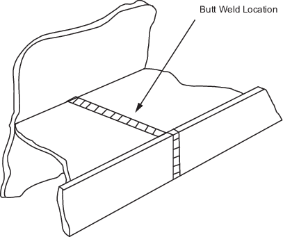
The length of butt welds located at checkpoints on longitudinal stiffeners may be
less than 300 mm for radiography or 500 mm for ultrasonic inspection. In such cases
inspect as much of the welds as access permits.
Figure 2.3.1 Inspection of checkpoints located on longitudinal stiffeners
Note for illustration, drawing shows
checkpoint in vertical butt direction. For seam welds, the checkpoint location may
lay in the horizontal direction.
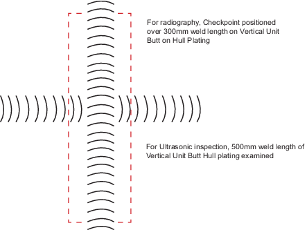
Figure 2.3.2 Checkpoint positions in way of
radiography and ultrasonic inspection on hull plating
Note for illustration, drawing shows checkpoint in vertical butt direction. For seam
welds, the checkpoint location may lay in the horizontal direction.
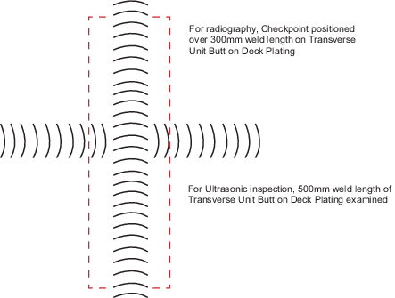
Figure 2.3.3 Checkpoint positions in way of radiography and ultrasonic inspection on deck
plating