
Section
5 Single bottom structure and appendages
5.1 General
5.1.1 The requirements
of this Section provide for single bottom construction in association
with transverse and longitudinal framing systems.
5.1.2 All girders
are to extend as far forward and aft as practicable and care is to
be taken to avoid any abrupt discontinuity. Where girders are cut
at bulkheads, their longitudinal strength is to be maintained.
5.1.3 Particular
care is to be taken to ensure that the continuity of structural strength
in way of the intersection of transverse floors and longitudinal girders
is maintained. The face flats of such stiffening members are to be
effectively connected.
5.1.4 The single
bottom structure in way of the keel and girders is to be sufficient
to withstand the forces imposed by dry-docking the craft.
5.2 Keel
5.3 Centre girder
5.3.1 A centreline
girder is, in general, to be fitted throughout the length of the hull
in association with transverse frames, transverses supporting longitudinals
or where the breadth of floors at the upper edge is greater than 1,5
m.
5.3.2 Centreline
girders are to be formed of intercostal or continuous plate webs with
a face flat welded to the upper edge. In all cases the face flat is
to be continuous. Where girder webs are intercostal, additional bracketing
and local reinforcement will be required to maintain the continuity
of structural strength.
5.3.8 The face
flat thickness is to be not less than the thickness of the web.
5.3.9 The ratio
of the width to thickness of the face flat is to be not less than
8 but is not to exceed 16.
5.4 Side girders
5.4.1 Where the
floor breadth at the upper edge exceeds 6,0 m side girders are to
be fitted at each side of the centre girder such that the spacing
between the side and centre girders or between the side girders themselves
is not greater than 3 metres. Side girders where fitted are to extend
as far forward and aft as practicable and are, in general, to terminate
in way of bulkheads, deep floors or other primary transverse structure.
5.4.5 In the
engineroom, additional side girders are generally to be fitted in
way of main machinery seatings. Where fitted, they are to be integrated
into the structure of the craft and extended forward and aft as far
as practicable.
5.5 Floors general
5.5.1 In transversely
framed craft, plate floors are generally to be fitted at each frame.
5.5.2 In longitudinally
framed craft, plate floors are to be fitted at every transverse web
frame and generally at a spacing not exceeding 2 m. Additional transverse
floors or webs are in general to be fitted at half web-frame spacing
in way of engine seatings and thrust bearings, pillars, skegs, ballast/bilge
keels and the bottom of the craft forward.
5.5.5 If the
side frames of the craft are attached to the floors by brackets, the
depth of floor may be reduced by 15 per cent and the floor thickness
determined using the reduced depth. The brackets are to be flanged
and have the same thickness as the floors, and their arm lengths clear
of the frame are to be the same as the reduced floor depth given above.
5.5.7 The face
flat thickness is to be not less than the thickness of the web and
the ratio of the web to the thickness of the face flat is to be not
less than 8 but is not to exceed 16.
5.5.9 Floors
are generally to be continuous from side to side.
5.5.10 The tops
of floors, in general, may be level from side to side. However, in
craft having considerable rise of floor the depth of the floor plate
may require to be increased to maintain the required section modulus.
5.5.11 The floors in the aft peak are to extend over and provide effective support
to the sterntube(s) where applicable.
5.6 Floors in machinery spaces
5.6.2 The depth
and section modulus of floors anywhere between engine or gearbox girders
is to be not less than that required to maintain continuity of structural
integrity or 50 per cent of the depth given in Pt 6, Ch 3, 5.5 Floors general 5.5.3. The face flat area and web thickness
for such reduced floor heights are to be increased appropriately in
order to maintain continuity of structural strength, see also
Pt 6, Ch 3, 4.12 Grouped frames.
5.7 Machinery seatings
5.7.2 Engine
holding-down bolts are to be arranged as near as practicable to floors
and longitudinal girders. When this cannot be achieved, bracket floors
are to be fitted.
5.7.3 Welding
in way of machinery seatings is to be double continuous and/or full
penetration where appropriate.
5.8 Drainholes in bottom structure
5.8.1 Sufficient
limber holes are to be cut in the internal bottom structure to allow
for the drainage of water from all parts of the bilge to the pump
suctions.
5.8.2 Particular
care is to be given to the positioning of limber holes to ensure adequate
drainage and to avoid stress concentrations.
5.8.3 Suitable
arrangements are to be made to provide free passage of air from all
parts of tanks to the air pipes.
5.9 Rudder horns
5.9.1 The shell
plating thickness in way of the rudder horn is to be increased locally,
by generally not less than 50 per cent but need not to be taken as
greater than the keel thickness required by Pt 6, Ch 3, 3.2 Plate keel.
5.9.2 The scantlings
of the rudder horn are to be such that the section modulus against
transverse bending, Z
r, at any horizontal
section XX (see
Figure 3.5.1 Rudder horn)
is not less than:
where
|
R
A
|
= |
total rudder area, in m2
|
|
V
|
= |
maximum
speed in the fully loaded condition, in knots |
|
K
V
|
= |
1,0 for displacement craft with 
|
|
|
= |
(1,12 - 0,005 V)3 for planing and semi-planing craft with 
|
|
a, b
|
= |
dimensions, in metres, as given in Figure 3.5.1 Rudder horn
|
|
L
WL
|
= |
is as defined in Pt 3, Ch 1, 6.2 Principal particulars 6.2.5
|
5.9.3 Rudder
horns are to be effectively integrated into the adjacent structure
and their design is to be such as to facilitate this.
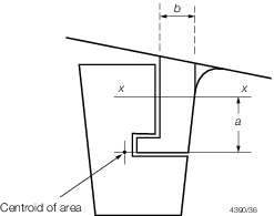
Figure 3.5.1 Rudder horn
5.10 Sternframes
5.11 Skeg construction
5.11.1 Skegs
are to be effectively integrated into the adjacent structure and their
design is to be such as to facilitate this.
5.11.3 The scantlings
of skegs are to be sufficient to withstand any docking forces that
they may be subjected to.
5.12 Forefoot and stem
5.12.1 The thickness
of plate stems at the waterline is to comply with the requirements
for plate keels as given in Pt 6, Ch 3, 3.2 Plate keel.
5.12.2 The forefoot
and stem is to be additionally reinforced with floors.
5.13 Transom knee
5.13.1 Centre
and side girders are to be bracketed to the transom framing members
by means of substantial knees. The face flat of the girders may be
gradually reduced to that of the transom stiffening members in accordance
with Figure 3.5.2 Transom knee.
5.13.2 Hard
spots are to be avoided in way of the end connections and care is
to be taken to ensure that the stiffening member to which the transom
knee is bracketed can satisfactorily carry the transmitted loads.
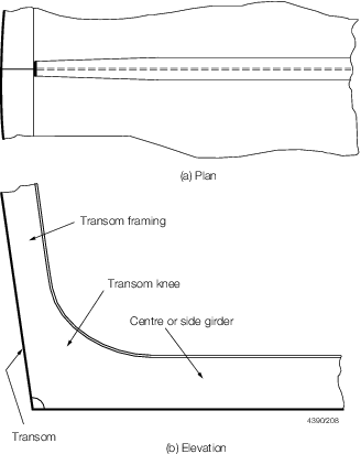
Figure 3.5.2 Transom knee
|