
Section
3 Sternframes and appendages
3.1 General
3.1.1 Sternframes,
rudder horns and boss end brackets may be constructed of cast or forged
steel, cast or forged aluminium alloy, fabricated from aluminium or
steel plate or moulded from fibre reinforced plastic dependent upon
the material of construction of the craft. Where shaft brackets are
fitted these may be either fabricated, cast or forged from steel or
aluminium alloy as applicable to the material of construction of the
main hull.
3.1.2 In castings,
sudden changes of section or possible constrictions to the flow of
metal during casting are to be avoided. All fillets are to have adequate
radii, which, in general, are to be not less than 50 to 75 mm, depending
on the size of the casting.
3.1.4 Sternframes,
rudder horns, shaft brackets, etc. are to be effectively integrated
into the craft structure, and their design is to be such as to facilitate
this.
3.2 Sternframes
3.2.1 The scantlings
of sternframes are to be determined from Table 3.3.1 Sternframes. In the case of very large craft, the scantlings and
arrangements may be required to be verified by direct calculations.
Table 3.3.1 Sternframes
| Item
|
Parameter
|
Requirement
|
| (1) Propeller posts
|
|
Cast steel
(see
Figure 3.3.1 Propeller posts)
|
Forged
steel
(see
Figure 3.3.1 Propeller posts)
|
Fabricated mild
steel
(see
Figure 3.3.1 Propeller posts)
|
|
|
l
|
165 
|
-
|
200  mm mm
|
|
|
r
|
20 
|
-
|
18  mm mm
|
|
|
tw
|
8 
|
-
|
6  mm mm
|
|
|
|
(need
not exceed 38 mm)
|
|
(need
not exceed 30 mm)
|
|
|
|
(see Notes 1 and 2)
|
|
(see Notes 1 and 2)
|
|
|
t1
|
12  (min 19 mm) (min 19 mm)
|
-
|
12  mm mm
|
|
|
t2
|
16  (min 25 mm) (min 25 mm)
|
-
|
-
|
|
|
W
|
115  mm mm
|
40  mm mm
|
140  mm mm
|
|
|
A
|
-
|
(10 +
0,5L
R)T cm2
|
-
|
|
|
|
|
where
L
R ≤ 60 m
|
|
|
|
|
|
40T cm2
|
|
|
|
|
|
where
L
R ≤ 60 m
|
|
| (2) Propeller boss (see Note 3 and
Figure 3.3.2 Propeller boss)
|
tb
|
 mm, but need not
exceed mm, but need not
exceed
|
| (3) Rudder posts or
axles
|
|
Single screw with integral solepiece,
see
Figure 3.3.5 Solepiece
|
Single screw with bolted rudder axle,
see
Figure 3.3.3 Rudder axle
|
Twin screw, integral with hull,
see
Figure 3.3.4 Rudder post for twin screw craft
|
| n
|
-
|
6
(see Note 4)
|
-
|
| r
|
-
|
-
|
20  mm mm
|
| rb
|
-
|
 Amm Amm
|
-
|
| tF
|
-
|
 bmm bmm
|
-
|
| t1
|
-
|
-
|
12  mm mm
|
| t2
|
-
|
-
|
15  mm mm
|
| t3
|
-
|
-
|
18 mm mm
|
| w
|
-
|
-
|
120  mm mm
|
| zPB1, zPB2
|
-
|
 mm mm
|
-
|
| ZT
|

|
-
|
-
|
 A A
|
-
|
 mm mm
|
-
|
|
|
|
but
need not exceeded
|
|
|
|
|
 mm mm
|
|
 b b
|
-
|
 mm or mm or
|
-
|
|
|
|
 mm mm
|
|
|
|
|
whichever is the greater
|
|
 PL1, PL1,  PL2 PL2
|
-
|
As for
rudder pintles
|
-
|
| bearing
pressure and pintle clerance
|
|
(see
Table 3.2.10 Pintle requirements)
|
|
| 4) Solepieces (see Notes 5,6 and 7)
|
|
With integral rudder
post, see
Figure 3.3.5 Solepiece
|
With bolted axle,
see
Figure 3.3.5 Solepiece
|
Open type (no rudder
post), see
Figure 3.3.5 Solepiece
|
| (a) Cast Steel
|
ZT
|
0,50W
cm3
|
0,95W
cm3
|
1,00W
cm3
|
|
|
ZV
|
0,35W
cm3
|
0,40W
cm3
|
0,50W
cm3
|
| (b) Fabricated mild
steel
|
ZT
|
0,42W
cm3
|
0,81W
cm3
|
0,85W
cm3
|
| Symbols
|
|
L
R, T as defined in Pt 3, Ch 1, 6.2 Principal particulars
|
|
n
|
= |
number of bolts in palm coupling |
|
|
r
b
|
= |
mean distance of bolt centres from centre of palm, in
mm |
|
|
t
b
|
= |
finished thickness of boss, in mm |
|
|
x |
= |
distance, in metres, from centre of rudder stock to
section under consideration |
|
|
A
|
= |
cross-sectional area of forged steel propeller post,
in cm2
|
|
|
A
R
|
= |
total rudder area, in m2
|
|
|
L
1
|
= |
L
R, but is to be taken not less than 90 m |
|
|
V
|
= |
maximum service speed, in knots, with the craft in
the loaded condition |
|
|
W
|
= |

|
|
|
Z
T
|
= |
section modulus against transverse bending, in
cm3
|
|
|
Z
V
|
= |
section modulus against vertical bending, in
cm3
|
|
|
δb
|
= |
diameter of coupling bolts, in mm |
|
|
δTS
|
= |
diameter of tail shaft, in mm |
|
Note
1. Where scantlings and proportions of
the propeller post differ from those shown in Item 1, the section
modulus about the longitudinal axis of the proposed section normal to
the post is to be equivalent to that with Rule scantlings. t
1 is to be not less than 8 (minimum of 19mm for cast steel sternframes) (minimum of 19mm for cast steel sternframes)
|
Note
2. On sternframes without solepieces, the
modulus of the post below the propeller boss, about the longitudinal
axis may be gradually reduced to not less than 85% of that required by
Note 1, subject to the same thickness limitations.
|
Note
3. In fabricated sternframes the
connection of the propeller post to the boss is to be by full
penetration welds.
|
Note
4. If more than six bolts are fitted, the
arrangements are to provide equivalent strength.
|
Note
5. In fabricated solepieces, transverse
webs are to be fitted spaced not more than 760 mm apart. Where the
breadth of the solepiece exceeds 900 mm, a centreline vertical web is
also to be fitted.
|
|
|
Note
7. For dredging and reclamation craft in
restricted service Groups G1, G2 or G3, the scantlings of an `open'
type solepiece are to be such that:
(a) Z
T = 0,625W cm3
(b) The cross-sectional area is not less than
18 cm2.
(c) The depth is not less than two-thirds of
the width at any point.
|
3.2.2 Fabricated
and cast propeller posts and rudder posts of twin screw craft are
to be strengthened at intervals by webs. In way of the upper part
of the sternframe arch, these webs are to line up with the floors.
3.3 Rudder horns
3.4 Shaft bossing
3.4.1 Where the
propeller shafting is enclosed in bossings extending back to the bearings
supporting the propellers, the aft end of the bossings and the bearings
are to be supported by substantially constructed boss end castings
or fabrications. These are to be designed to transmit the loading
from the shafting efficiently into the craft's internal structure.
3.4.2 For shaft
bossings attached to shaft brackets, the length of the boss is to
be adequate to accommodate the aftermost bearing and to allow for
proper connection of the shaft brackets.
3.4.3 Cast steel
supports are to be suitably radiused where they enter the main hull
to line up with the boss plating radius. Where the hull sections are
narrow, the two arms are generally to be connected to each other within
the craft. The arms are to be strengthened at intervals by webs.
3.4.4 Fabricated
supports are to be carefully designed to avoid or reduce the effect
of hard spots. Continuity of the arms into the craft is to be maintained,
and they are to be attached to substantial floor plates or other structure.
The connection of the arms to the bearing boss is to be by full penetration
welding.
3.4.5 The scantlings
of supports will be specially considered. In the case of certain high
powered craft, direct calculations may be required.
3.4.6 The boss
plating is generally to be radiused into the shell plating and supported
at the aft end by diaphragms at every frame. These diaphragms are
to be suitably stiffened and connected to floors or a suitable arrangement
of main and deep web frames. At the forward end, the main frames may
be shaped to fit the bossing, but deep webs are generally to be fitted
not more than four frame spaces apart.
3.5 Shaft brackets
3.5.2 Where the
propeller shafting is exposed to the sea for some distance clear of
the main hull, it is generally to be supported adjacent to the propeller
by independent brackets having two arms. In very small craft the use
of single arm brackets will be considered.
3.5.3 Fabricated
brackets are to be designed to avoid or reduce the effect of hard
spots and ensure a satisfactory connection to the hull structure.
The connection of the arms to the bearing boss is to be by full penetration
welding.
3.5.4 Where bracket
arms are carried through the shell plating, they are to be attached
to floors or girders of increased thickness. The shell plating is
to be increased in thickness and connected to the arms by full penetration
welding.
3.5.5 In the
case of certain high powered craft direct calculations may be required.
3.5.7 The length
of the shaft bracket boss, lb
, is to be sufficient
to support the length of the required bearing. In general lb
is
not to be less than 4dt
, where dt
is
the Rule diameter of the screwshaft, in mm, see
Pt 11, Ch 2, 4.4 Screwshafts and tube shafts. Proposals for a reduction
in the required shaft bracket boss length will be considered in conjunction
with details of the bearing material, allowable bearing operating
pressure and installation arrangements, see
Pt 11, Ch 2, 4.16 Sternbushes and sterntube arrangements 4.16.2. However in no
case is lb
to be less than the greater of:
-
2dt
;
or
-
that recommended
by the bearing manufacturer; or
-
as required by Pt 3, Ch 3, 3.4 Shaft bossing 3.4.2.
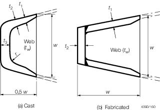
Figure 3.3.4 Rudder post for twin screw craft
3.5.8 Where the shaft and the shaft bracket boss are
of the same material, the thickness of the shaft bracket boss is not to be less than
dt
/4. Where the shaft and the shaft bracket boss are of dissimilar materials, the
thickness of the boss, tb
, is to be not less than:

Note In no case is t
b to be taken as less than 12 mm.
where
|
d
t
|
= |
Rule diameter of the screwshaft, in the appropriate screwshaft
material, in mm, see
Pt 11, Ch 2, 4 Design and construction
|
|
f
1
|
= |
σS/σB but not less than 0,825 |
|
σS
|
= |
ultimate tensile strength of the shaft material, in N/mm2
|
|
σB
|
= |
ultimate tensile strength of the boss material, in N/mm2. |
3.5.9 The design
of the shaft brackets with regard to hydrodynamic effects causing
vibrational excitations as well as disturbance of the hydrodynamic
flow into the propeller and rudders is outside the scope of classification.
However, it is recommended that the effects of periodic excitation
caused by vortex shedding or other sources be carefully examined in
order to prevent excessive structural vibration. The responsibility
for such investigation rests with the designer.
3.6 Single arm shaft brackets (`P' - brackets)
3.6.1 Single
arm shaft brackets are to have a section modulus, Z
xx,
at the palm of not less than that determined from the formula:
The cross-sectional area of the bracket at the boss is to be
not less than 60 per cent of the area of the bracket at the palm.
3.6.2 For single
arm shaft brackets a vibration analysis may be required if deemed
necessary by LR.
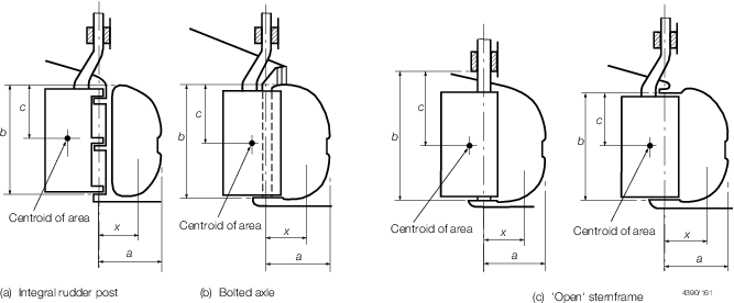
Figure 3.3.5 Solepiece
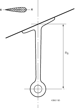
Figure 3.3.6 Single arm shaft bracket
3.7 Double arm shaft brackets (`A' - brackets)
3.7.1 The angle
between the arms for double arm shaft brackets is to be generally
not less than 50o. Proposals for the angle between the
arms to be less than 50o will be specially considered with
supporting calculations to be submitted by the designers.
3.8 Intermediate shaft brackets
3.9 Attachment of shaft brackets by welding
3.9.1 Fabricated
supports are to be carefully designed to avoid or reduce the effect
of hard spots. Continuity of the arms into the craft is to be maintained,
and they are to be attached to substantial floor plates or other structure.
The connection of the arms to the bearing boss is to be by full penetration
welding.
3.10 Attachment of shaft brackets by bolting
3.10.1 The bottom
shell thickness in way of the double arm propeller bracket palms is
to be increased by 50 per cent. The bottom shell thickness in way
of single arm propeller brackets palms is to be doubled in thickness.
The insert plates, or reinforced shell laminate in FRP craft, are
to be additionally supported by substantial floor plates or other
structure.
3.10.2 Where
shaft brackets are attached by bolts, they are to be provided with
substantial palms securely attached to the hull structure which is
to be adequately stiffened in way. Where bolts are used, the nuts
are to be suitably locked.
3.10.3 The bracket
palms may be bolted directly onto the shell using a suitable bedding
compound. The palms may be bolted onto suitable shims or chocking
compound, of an approved type, to facilitate alignment.
3.10.4 Where
brackets are bolted onto resin chocks, plans indicating the following
information are to be submitted for approval:
-
The thrust and torque loads, where applicable,
that will be applied to the chocked item.
-
The torque load to be applied to the bracket
mounting bolts.
-
The material of the bracket mounting bolts.
-
The number, thread size, shank diameter and
length of the mounting bolts.
3.10.5 The minimum
thickness of a resin chock is to be 12 mm.
3.10.7 The diameter
of the propeller bracket mounting bolts is to be not less than:
and not less than the shell plate thickness in way
of the palm or 12 mm, whichever is greater
3.10.8 Where
the shaft bracket and the shaft bracket mounting bolts are of dissimilar
materials (which are galvanically compatible), the diameter of the
propeller bracket mounting bolts, as determined from Pt 3, Ch 3, 3.10 Attachment of shaft brackets by bolting 3.10.7, is to be modified in proportion
to the square root of the yield strengths of the particular materials.
The corrected bolt diameter of the dissimilar material is to be not
less than the propeller bracket boss thickness.
3.10.9 The propeller
bracket palms are to have fitted bolts, and suitable arrangements
provided to lock the nuts.
3.10.10 A washer
plate is to be provided, generally of equal dimensions to the bracket
palm with thickness t
b/6 mm, subject to a
minimum of 3 mm.
3.11 Attachment of shaft brackets by bonding
3.11.1 Proposals
to connect shaft brackets to FRP hulls by bonding will be the subject
of special consideration. Details of the following are to be submitted:
-
Preparation of the
hull penetration and internal bonding surface.
-
Details of transverse
through pinning of the shaft bracket strut.
-
Details of over
bonding of strut and pin arrangement and subsequent integration of
strut into primary hull structure.
3.12 Alignment of shaft brackets
3.12.1 Particular
care is to be paid to the alignment of shaft brackets to minimise
vibration and cyclic loadings being transmitted from the propulsion
shafting and propellers into the hull structure.
3.12.3 The alignment of shaft brackets connected by welding or bonding may be
facilitated by boring of the bracket boss after attachment of the shaft bracket and
sterntube.
3.13 Sterntubes
3.13.1 The sterntube
construction may be of aluminium alloy, steel, bronze or fibre reinforced
plastic.
3.13.2 The sterntube
scantlings are to be individually considered.
3.13.3 For steel
and aluminium hulls, the bottom shell, in way of the sterntube, is
to be additionally reinforced by means of an insert plate to increase
the bottom shell thickness by 50 per cent.
3.13.4 For FRP
hulls, the bottom shell laminate, in way of the sterntube, is to be
locally increased by 50 per cent by gradual tapering of the laminate.
The increased thickness in way of the sterntube need not exceed the
Rule keel thickness requirement.
3.13.5 For FRP
sandwich hulls the shell in way of the stern tube connection is to
be either:
-
Reduced from sandwich hull construction to
single skin laminate by removal of the core and by combining the inner
and outer skins. The single skin region is then to be additionally
reinforced by a minimum of 50 per cent of the sum of the inner and
outer sandwich laminate. The increased thickness in way of the sterntube
need not be greater than the Rule keel thickness requirement.
-
Reduced from the sandwich hull construction to a single skin laminate
by removal of the core and combining the inner and outer skins. After bonding in
the sterntube to the single skin laminate the foam core and the inner skin are to
be reinstated.
-
Proposals to replace the sandwich core with
a core having higher core shear strength and compressive strength
than that of the adjacent structure prior to bonding the tube to the
inner and outer skins will be the subject of special consideration.
3.13.6 The sterntube
may be connected to the shell by bonding, bolting or welding as applicable
depending upon the construction material of the shell.
3.13.7 When
bonding in sterntubes the bonding angle laminate weight is to be not
less than the Rule minimum bottom weight. FRP tubes are to be thoroughly
abraded and degreased prior to installation and laminating. Bonded
in metallic tubes are to be knurled in way of the bonding material
and thoroughly degreased prior to installation. During the bonding
operation particular care is to be given to maintaining the sterntube
alignment.
3.13.8 Where
sterntubes are to be retained by bolting, they are to be provided
with a substantial flange securely attached to the hull structure.
Where bolts are used, the nuts are to be suitably locked.
3.13.9 Where sterntubes are to be welded to hull insert plates full penetration
welding is required.
3.13.11 The
region where the shafting enters the craft, and the bearing in way,
are to be adequately supported by floors or deep webs.
3.13.12 The
shaft bearings are to be secured against rotation within the sterntube.
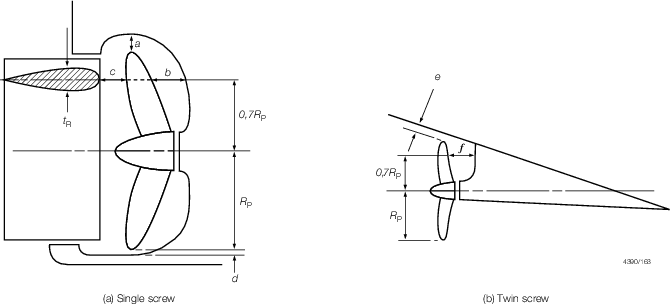
Figure 3.3.8 Propeller clearance
3.13.14 Where difficulty in welding or bonding of sterntube to the hull is anticipated due to
small clearances or tight angles, a local cofferdam or watertight compartment of
moderate volume is to be fitted enclosing the hull penetration and the sterntube. Where
the sterntube penetrates the inboard boundary of the watertight compartment or
cofferdam, it is to be suitably supported and sealed.
3.14 Solepieces
3.15 Propeller hull clearances
3.15.1 Recommended
minimum clearances between the propeller and the sternframe, rudder
or hull are given in Table 3.3.2 Recommended propeller hull
clearances.
These are the minimum distances considered desirable in order to expect
reasonable levels of propeller excited vibration. Attention is drawn
to the importance of the local hull form characteristics, shaft power,
water flow characteristics into the propeller disc and cavitation
when considering the recommended clearances.
Table 3.3.2 Recommended propeller hull
clearances
Number
of Blades
|
Hull clearances for single screw, in metres,
|
Hull clearances for twin screw
|
|
see
Figure 3.3.8 Propeller clearance
|
in metres, see
Figure 3.3.8 Propeller clearance
|
| a
|
b
|
c
|
d
|
e
|
f
|
| 3
|
1,20Kδ
|
1,80Kδ
|
0,12δ
|
0,03δ
|
1,20Kδ
|
1,20Kδ
|
| 4
|
1,00Kδ
|
1,50Kδ
|
1,12δ
|
0,03δ
|
1,00Kδ
|
1,20Kδ
|
| 5
|
0,85Kδ
|
1,275Kδ
|
0,12δ
|
0,03δ
|
0,85Kδ
|
0,85Kδ
|
| 6
|
0,75Kδ
|
1,125Kδ
|
0,12δ
|
0,03δ
|
0,75Kδ
|
0,75Kδ
|
|
|
|
|
|
|
|
|
| Minimum value
|
0,10δ
|
0,15δ
|
t
R
|
-
|
3 and 4 blades
|
0,15δ
|
|
|
|
|
|
|
0,20δ
|
|
|
|
|
|
|
|
5 and 6 blades
|
|
|
|
|
|
|
|
0,16δ
|
|
| Symbols
|
|
L
R and C
b as defined in Pt 3, Ch 1, 6.1 General
|
|
t
R
|
= |
thickness of rudder, in metres measured at
0,7R
p above the shaft centreline |
|
P
s
|
= |
designed power on one shaft, in kW |
|
R
p
|
= |
propeller radius, in metres |
|
δ |
= |
propeller diameter, in metres |
|
Note The above recommended minimum clearances also apply to
semi-spade type rudders.
|
|