
Section
4 Buckling control
4.1 General
4.1.1 This Section
contains the requirements for buckling control of plate panels subject
to in-plane compressive and/or shear stresses and buckling control
of primary and secondary stiffening members subject to axial compressive
and shear stresses.
4.1.2 The requirements
for buckling control of plate panels are contained in Pt 6, Ch 7, 4.3 Plate panel buckling requirements. The requirements for secondary
stiffening members are contained in Pt 6, Ch 7, 4.7 Secondary stiffening in direction of compression and Pt 6, Ch 7, 4.8 Secondary stiffening perpendicular to direction of compression. The requirements for primary members
are contained in Pt 6, Ch 7, 4.9 Buckling of primary members and Pt 6, Ch 7, 4.10 Shear buckling of girder webs.
4.1.4 The buckling
requirements are to be met using the net scantlings, hence any additional
thickness for corrosion margin or Owners extra is not included in
scantlings used to assess the buckling performance.
4.2 Symbols
4.2.1 The symbols
used in this Section are defined below and in the appropriate sub-Section:
|
t
p
|
= |
thickness of plating, in mm |
|
A
R
|
= |
panel aspect ratio |
| = |

|
|
a
|
= |
panel
length, i.e. parallel to direction of compressive stress being considered,
in mm |
|
b
|
= |
panel
breadth i.e. perpendicular to direction of compressive stress being
considered, in mm |
|
S
p
|
= |
span of primary members, in metres |
|
σo
|
= |
specified
minimum yield strength of the material, in N/mm2
|
|
σe
|
= |
elastic
compressive buckling stress, in N/mm2
|
|
σc
|
= |
critical
compressive buckling stress, including the effects of plasticity where
appropriate, in N/mm2
|
|
τo
|
= |
specified
minimum yield shear stress of material, in N/mm2
|
| = |
 N/mm2 N/mm2
|
|
E
|
= |
modulus
of elasticity of material, in N/mm2
|
|
τe
|
= |
elastic
shear buckling stress, in N/mm2
|
|
τc
|
= |
critical
shear buckling stress, in N/mm2
|
|
b
eb
|
= |
lesser of 1,9t
p
 or 0,8b mm or 0,8b mm
|
|
A
te
|
= |
cross-sectional area of secondary stiffener, in cm2,
including an effective breadth of attached plating, b
eb
|
|
s
|
= |
length
of shorter edge of plate panel, in mm (typically the spacing of secondary
stiffeners) |

|
= |
length of longer edge
of plate panel, in metres. |
|
S
|
= |
spacing
of primary member, in metres (measured in direction of compression). |
4.3 Plate panel buckling requirements
4.3.1 This Section
gives methods for evaluating the buckling strength of plate panels
subjected to the following load fields:
-
uni-axial compressive
loads;
-
shear loads;
-
bi-axial compressive
loads;
-
uni-axial compressive
loads and shear loads;
-
bi-axial compressive
loads and shear loads.
4.3.7 However,
where some members of the structure have been designed such that elastic
buckling of the plate panel between the stiffeners is allowable, then
the requirements of Pt 6, Ch 7, 4.5 Additional requirements for plate panels which buckle elastically must be
applied to the buckling analysis of the stiffeners supporting the
plating. In addition, panels which do not satisfy the panel buckling
requirements must be indicated on the appropriate drawing and the
effect of these panels not being effective in transmitting compressive
loads taken into account for the hull girder strength calculation.
4.3.8 In general
the plate panel buckling requirements for more complex load fields, see
Pt 6, Ch 7, 4.3 Plate panel buckling requirements 4.3.1.(c), Pt 6, Ch 7, 4.3 Plate panel buckling requirements 4.3.1.(d) and Pt 6, Ch 7, 4.3 Plate panel buckling requirements 4.3.1.(e), are to be complied with. Where this is not possible, due
to elastic buckling of the panel, then the critical buckling stress,
σχ, may be based on the ultimate collapse strength
of the plating, συ from Pt 6, Ch 7, 4.5 Additional requirements for plate panels which buckle elastically 4.5.4, instead of the elastic buckling stress, σε,
derived in Pt 6, Ch 7, 4.3 Plate panel buckling requirements 4.3.5. In addition,
the requirements of Pt 6, Ch 7, 4.5 Additional requirements for plate panels which buckle elastically are to
be met for the supporting secondary stiffeners and primary members.
4.4 Derivation of the buckling stress for plate panels
4.4.2 The critical
shear buckling stress, τc, for a plate panel subjected
to pure in-plane shear load is to be derived in accordance with Table 7.4.1 Buckling stress of plate
panels.
Table 7.4.1 Buckling stress of plate
panels
| Mode
|
Elastic buckling stress,
N/mm2, see Note 1
|
|
| (a) Uni-axial
compression:
|
|
|
|
(i) Long narrow panels,
loaded on the narrow edge
|
|
|
(ii) Short broad panels,
|
A
R < 1
σe =
0,9Cϕ 
|
| (b) Pure shear:
|
See Note 2
|
|
Note
1. The critical buckling stresses, in
N/mm2, are to be derived from the elastic buckling
stresses as follows:
|
|
σc
|
= |
σe when σe <
|
|
|
= |
σo
 when σe ≥ when σe ≥
|
σc is defined in Pt 6, Ch 7, 4.2 Symbols 4.2.1
σo is defined in Pt 6, Ch 7, 4.2 Symbols 4.2.1
|
|
τc
|
= |
τe when τe < 
|
|
|
= |
τo
 when τe ≥ when τe ≥ 
|
τc is defined in Pt 6, Ch 7, 4.2 Symbols 4.2.1
τo is defined in Pt 6, Ch 7, 4.2 Symbols 4.2.1
|
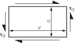
Note 2.
u is to be the minimum dimension
|
| Symbols and definitions
|
|
σe
|
= |
elastic compressive buckling stress, in
N/mm2
|
|
τe
|
= |
elastic shear buckling stress, in N/mm2
|
|
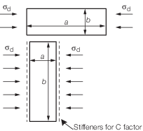
a and b
|
= |
are the panel dimensions in mm, see figures
above |
|
t
p
|
= |
thickness of plating, in mm |
|
φ |
= |
stress distribution factor for linearly varying
compressive stress across plate width |
|
|
= |
0,47 μ2 - 1,4 μ + 1,93 for μ ≥ 0 |
|
μ |
= |
 where σd1 and σd2 are the
smaller and larger average compressive stresses respectively where σd1 and σd2 are the
smaller and larger average compressive stresses respectively |
|
E
|
= |
Young's Modulus of elasticity of material, in
N/mm2
|
|
C
|
= |
stiffener influence factor for panels with stiffeners
perpendicular to compressive stress |
| = |
1,3 when plating stiffened by floors or deep
girders |
| = |
1,21 when stiffeners are built up profiles or rolled
angles |
| = |
1,10 when stiffeners are bulb flats |
| = |
1,05 when stiffeners are flat bars |
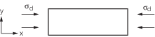
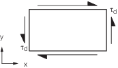
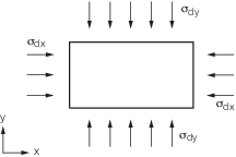
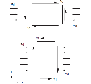
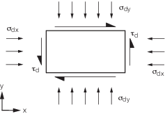
σd and τd are the design compressive
and design shear stresses in the direction illustrated in the figures.
With linearly varying stress across the plate panel, σd is to
be taken as σd2
|
Table 7.4.2 Plate panel buckling
requirements
|
|
Stress
field
|
Buckling interaction
formula
|
|
| (a)
|
uni-axial compressive loads
|

|
|
| (b)
|
shear
loads
|

|
|
| (c)
|
bi-axial
compressive loads
|
for A
R = 1,0

for other aspect ratios, ie. A
R ≠ 1,0

when G is taken from
Figure 7.4.2 Secondary stiffening perpendicular to direction of compression
|
|
| (d)
|
uni-axial
compressive loads
plus shear load
|
for AR > 1

for A
R ≤ 1

|
|
| (e)
|
bi-axial
compressive loads
plus shear loads
|

|
|
| Symbols
|
|
|
|
|
|
σdx
|
= |
design compressive stress in x direction |
|
|
σdy
|
= |
design compressive stress in the y direction |
|
|
|
|
|
|
|
|
|
|
τd
|
= |
design shear stress, in N/mm2
|
|
|
|
4.4.3 For welded
plate panels with plating thicknesses below 8 mm the critical compressive
buckling stress is to be reduced to account for the presence of residual
welding stresses. The critical buckling stress is to be taken as the
minimum of:
or
where
|
σr
|
= |
reduction
in compressive buckling stress due to residual welding stresses |
| = |

|
|
βRS
|
= |
residual
stress coefficient dependent on type of weld (average value of βRS to be taken as 3) b, t
p and
σo are defined in Pt 6, Ch 7, 4.2 Symbols 4.2.1
|
4.4.4 In general
the effect of lateral loading on plate panels (for example hydrostatic
pressure on bottom shell plating) may be neglected and the critical
buckling stresses calculated considering the in-plane stresses only.
4.4.5 Unless
indicated otherwise, the effect of initial deflection on the buckling
strength of plate panels may be ignored.
4.5 Additional requirements for plate panels which buckle elastically
4.5.1 Elastic
buckling of plate panels between stiffeners occurs when both the following
conditions are satisfied:
-
The design compressive
stress, σd, is greater than the elastic buckling stress
of the plating, σe,
σd >
σe
-
The elastic buckling
stress is less than half the yield stress
σe ≤ 
4.5.2 Elastic
buckling of local plating between stiffeners, including girders or
floors etc, may be allowed if all of the following conditions are
satisfied:
-
The critical buckling
stress of the stiffeners in all buckling modes is greater than the
axial stress in the stiffeners after redistribution of the load from
the elastically buckled plating into the stiffeners, hence

-
Maximum predicted
loadings are used in the calculations.
-
Functional requirements
will allow a degree of plating deformation.
where
where
|
i |
= |
a, t, w or f depending
on the mode of buckling. |
|
λσ |
= |
is the buckling factor of safety |
| = |
1,25 |
Table 7.4.3 Buckling stress of secondary
stiffeners
| Mode
|
Elastic
buckling stress, N/mm2
|
Critical
buckling stress, N/mm2
see Note 1
|
| (a) Overall buckling (perpendicular to plane of
plating without rotation of cross-section)
|
|
σe(a)
|
= |
C
f0,001E

|
|
σc(a)
|
| (b) Torsional buckling
|
|
σe(t)
|
= |

|
|
σc(t)
|
| (c) Web buckling (excluding flat bar
stiffeners)
|
|
σe(w)
|
= |
3,8E

|
|
σc(w)
|
| (d) Flange buckling
|
|
σe(f)
|
= |
0,39E

|
|
σc(f)
|
| Symbols
|
|
|
|
t
w
|
= |
web thickness, in mm |
|
|
b
f
|
= |
flange width, in mm (including web thickness) |
|
|
|
 e
e
|
= |
effective span length of stiffener, in metres |
|
|
C
f
|
= |
end constraint factor |
| = |
1 where both ends are pinned |
| = |
2 where one end pinned and the other end fixed |
| = |
4 where both ends are fixed |
|
|
E
|
= |
Young's Modulus of elasticity of the material, in
N/mm2
|
|
 a
a
|
= |
moment of inertia, in cm4, of
longitudinal, including attached plating of effective width
b
eb, see Note |
|
| t
p and σo are given in Pt 6, Ch 7, 4.2 Symbols 4.2.1
|
| A
te and b
eb are given in Pt 6, Ch 7, 4.2 Symbols 4.2.1
|
 t
t
|
= |
St.Venant’s moment of inertia, in cm4, of
longitudinal (without attached plating) |
| = |
 10–4 for flat bars 10–4 for flat bars |
| = |
 10–4 for built up profiles, rolled
angles and bulb plates 10–4 for built up profiles, rolled
angles and bulb plates |
|
 p
p
|
= |
polar moment of inertia, in cm4, of profile
about connection of stiffener to plating |
| = |
 10–4 for flat bars 10–4 for flat bars |
| = |
 10–4 for built up profiles, rolled
angles and bulb plates 10–4 for built up profiles, rolled
angles and bulb plates |
|
 w
w
|
= |
sectorial moment of inertia, in cm6, of
profile and connection of stiffener to plating |
| = |
 10–6 for flat bars 10–6 for flat bars |
| = |
 10–6 for ‘Tee’ profiles 10–6 for ‘Tee’ profiles |
| = |
 (t
f (b
f
2 + 2b
f
d
w + 4d
w
2) + 3t
w
b
f
d
w) 10–6 for ‘L’ profiles, rolled
angles and bulb plates (t
f (b
f
2 + 2b
f
d
w + 4d
w
2) + 3t
w
b
f
d
w) 10–6 for ‘L’ profiles, rolled
angles and bulb plates |
|
|
C
|
= |
spring stiffness exerted by supporting plate
panel |
| = |

|
|
|
k
p
|
= |
1 – ηp, and is not to be taken as less
than zero. For built up profiles, rolled angles and bulb plates,
k
p need not be taken less than 0,1 |
|
|
ηp
|
= |

|
|
|
|
| m is determined as follows; e.g. m = 2 for K = 25
|
| K
|
0 to 4
|
4 to 36
|
36 to 144
|
144 to 400
|
400 to 900
|
900 to 1764
|
(m-1)2
m
2 to m
2(m+1)2
|
| m
|
1
|
2
|
3
|
4
|
5
|
6
|
m
|
|
K
|
= |

|
|
σd is the design stress, in N/mm2
all other symbols are as defined in Pt 6, Ch 7, 4.2 Symbols 4.2.1.
|
|
|
|
|
4.5.3 The effective
breadth of attached plating for stiffeners, girder or beams that is
to be used for the determination of the critical buckling stress of
the stiffeners attached to plating which buckles elastically is to
be taken as follows:
|
b
eu
|
= |
 mm mm
|
where
|
b
eu
|
= |
effective panel breadth perpendicular to direction of compressive
stress being considered |
b is given in Pt 6, Ch 7, 4.2 Symbols 4.2.1.
4.5.4 The ultimate
buckling strength of plating, συ, which buckles
elastically, may be determined as follows:
-
shortest edge loaded,
i.e. AR ≥ 1:
|
σu
|
= |
 N/mm2 N/mm2
|
-
longest edge loaded,
i.e. AR < 1:
|
σu
|
= |
 N/mm2 N/mm2
|
where
|
Ω |
= |

|
A
R and s are
defined in Pt 6, Ch 7, 4.2 Symbols 4.2.1.
t
p, E and σo are defined
in Pt 6, Ch 7, 4.2 Symbols 4.2.1.
4.5.5 The axial
stress in stiffeners attached to plating which is likely to buckle
elastically is to be derived as follows:
|
σde
|
= |
σd

|
where
σd is the axial
stress in the stiffener when the plating can be considered fully effective
|
A
t
|
= |
A
s +  cm2 cm2
|
|
A
tb
|
= |
A
s +  cm2 cm2
|
where
b and b
eu are given in Pt 6, Ch 7, 4.5 Additional requirements for plate panels which buckle elastically 4.5.3
t is the plating thickness, in mm
A
s is the stiffener area in cm2
4.6 Shear buckling of stiffened panels
4.6.3 The critical
shear buckling stress, τχ, may be determined from τε, see Note 2 in Table 7.4.1 Buckling stress of plate
panels.
Table 7.4.4 Buckling factor of safety
| Structural
item
|
Buckling
factor of safety (2) Compressive stresses, λσ
|
Buckling
factor of safety (3) Shear stresses, λτ
|
| Bottom
shell plating
|
1,0
|
–
|
| Inner bottom
plating
|
1,0
|
–
|
| Deck
plating
|
1,0
|
–
|
| Side shell
plating
|
1,0
|
1,1
|
| Longitudinal
bulkhead plating
|
1,0
|
1,1
|
| Double
bottom girders
|
1,0
|
1,1
|
| Longitudinal
girders
|
1,0
|
1,1
|
| Superstructures/deckhouses (partially longitudinally effective)
|
1,0
|
–
|
| Longitudinal
secondary stiffeners
|
1,1(1)
|
–
|
| Girder and
floor web plating subject to local loads
|
1,1
|
1,2
|
Note
2 Buckling factor of safety to be applied
to the compressive stress due to global longitudinal stresses.
Note
3 Buckling factor of safety to be applied
to the shear stress.
|
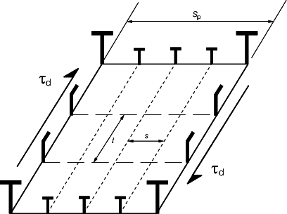
Figure 7.4.1 Shear buckling of stiffened panels
4.7 Secondary stiffening in direction of compression
4.7.1 The buckling
performance of stiffeners will be considered satisfactory if the following
conditions are satisfied:
where
|
|
= |
σc(a), σc(t), σc(w) and
σc(f) are the critical buckling stress of the stiffener
for each mode of failure, see
Pt 6, Ch 7, 4.7 Secondary stiffening in direction of compression 4.7.2
|
|
|
= |
σd is the design compressive stress, see
also
Pt 6, Ch 7, 4.5 Additional requirements for plate panels which buckle elastically and Pt 6, Ch 7, 4.1 General 4.1.3
|
|
|
= |
λσ is the buckling factor of safety given
in Table 7.4.4 Buckling factor of safety. The value of λσ to be chosen depends on the buckling assessment of the
attached plating, see Note 1, Table 7.4.4 Buckling factor of safety.
|
4.7.2 The critical
buckling stresses for the overall, torsional, web and flange buckling
modes of longitudinals and secondary stiffening members under axial
compressive loads are to be determined in accordance with Table 7.4.3 Buckling stress of secondary
stiffeners.
4.7.4 The critical
buckling stresses of the stiffener web, σc(w), and
flange, σc(f), are to be greater than the critical
torsional buckling stress, hence:
σc(w) > σc(t)
σc(f) > σc(t)
4.7.5 To ensure
that overall buckling of the stiffened panel cannot occur before local
buckling of the secondary stiffener, the critical overall buckling
stress σc(a), is to be greater than the critical torsional
buckling stress, hence:
σc(a) > σc(t)
4.8 Secondary stiffening perpendicular to direction of compression
4.8.1 Where a
stiffened panel of plating is subjected to a compressive load perpendicular
to the direction of the stiffeners, see
Figure 7.4.2 Secondary stiffening perpendicular to direction of compression, e.g. a transversely stiffened
panel subject to longitudinal compressive load, the requirements of
this Section are to be applied.
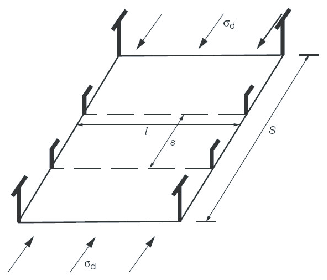
Figure 7.4.2 Secondary stiffening perpendicular to direction of compression
4.9 Buckling of primary members
4.9.2 To prevent
global buckling from occurring before local panel buckling, transverse
primary girders supporting axially loaded longitudinal stiffeners
are to have a sectional moment of inertia, including attached plating,
of not less than the following:
S
p and s are
as defined in Pt 6, Ch 7, 4.2 Symbols 4.2.1, see
also
Figure 7.4.1 Shear buckling of stiffened panels
 g
g
|
= |
sectional
moment of inertia including attached plating |
where
|
σep
|
= |
1,2σd N/mm2 for σe(a) < 
|
| = |
 for σe(a) ≥ for σe(a) ≥
|
σd is design stress, in N/mm2
σo and Ate are as defined in Pt 6, Ch 7, 4.2 Symbols 4.2.1
σe(a) is
the elastic column buckling stress, see
Pt 6, Ch 7, 4.7 Secondary stiffening in direction of compression 4.7.2
E is
defined in Pt 6, Ch 7, 4.2 Symbols 4.2.1.
le is defined in Table 7.4.3 Buckling stress of secondary
stiffeners
4.10 Shear buckling of girder webs
4.11 Pillars and pillar bulkheads
|