
Section
2 Hull girder strength for mono-hull craft
2.1 General
2.1.1 Longitudinal
strength calculations are to be submitted for all craft with a Rule
length, L
R, exceeding 50 m covering the range
of load and ballast conditions proposed, in order to determine the
required hull girder strength. Still water, static wave and dynamic
bending moments and shear forces are to be calculated for both departure
and arrival conditions.
2.1.2 For craft
of ordinary hull form with a Rule length, L
R,
less than 50 m, the minimum hull girder strength requirements are
generally satisfied by scantlings obtained from local strength requirements.
However longitudinal strength calculations may be required at LR's
discretion, dependent upon the form, constructional arrangement and
proposed loading.
2.1.3 Where the
Rule length, L
R, of the craft exceeds 75 m,
or for new designs of large, structurally complicated craft, the design
loads and scantling determination formulae in this Chapter are to
be supplemented by direct calculation and structural analysis by 3-D
finite element methods. These supplementary calculations are to include
the results of model tests and full scale measurement where available
or required by LR. Full details of such methods and all assumptions
and calculations, which are to be based on generally accepted theories,
are to be submitted for appraisal.
2.2 Bending strength
2.2.1 The effective
geometric properties of the midship section are to be calculated directly
from the dimensions of the section using only the effective material
elements which contribute to the global longitudinal strength irrespective
of the grades of steel incorporated in the construction. For the purposes
of this analysis an element may be of deck plating, longitudinal girder,
inner bottom, etc. or other continuous member.
2.2.2 The contribution
that higher tensile steel makes to the global strength is based upon
the strain in that material in relation to the allowable strain in
mild steel. Therefore, the maximum permissible hull vertical bending
stress, σp, for the design analysis is not to be
taken greater than that determined from the following:
where
|
σp
|
= |
is
as defined in Pt 6, Ch 6, 2.2 Bending strength 2.2.3
|

|
= |
the maximum distance,
in metres, above or below the neutral axis of the hull cross-section
to any effective higher tensile steel element contributing to global
longitudinal strength. |

|
= |
the maximum distance,
in metres, above or below the neutral axis of the hull cross-section
to any effective mild steel element contributing to global longitudinal
strength. |
2.2.3 The longitudinal
strength of craft
with
 ≥ 3,0 is to satisfy both the following criteria: ≥ 3,0 is to satisfy both the following criteria:
σk + σl + σt < 1,2 σP and
σd < σP
L
WL is as defined in Pt 3, Ch 1, 6.2 Principal particulars 6.2.5
σk, σ , σt and σd are given
in Table 6.2.1 Longitudinal component
stresses , σt and σd are given
in Table 6.2.1 Longitudinal component
stresses
σs is as defined in Pt 6, Ch 6, 1.2 Symbols and definitions 1.2.1.
Table 6.2.1 Longitudinal component
stresses
| Component stress
type
|
Nominal stress
(N/mm2)
|
| Hull girder bending stress at
strength deck amidships
|
|
| Hull girder bending stress at keel
amidships
|
|
| Actual stress in bottom longitudinals
amidships due to design pressure load
|
|
| Actual stress in bottom plating
amidships due to design pressure load
|
|
| Symbols and definitions
|
|
Z
d
|
= |
actual section modulus at deck, in m3
|
|
Z
k
|
= |
actual section modulus at keel, in m3
|
Z

|
= |
actual section modulus of bottom longitudinal
stiffener amidships, in cm3
|
s,  e, β and t
pare as defined in Pt 6, Ch 6, 1.2 Symbols and definitions.
e, β and t
pare as defined in Pt 6, Ch 6, 1.2 Symbols and definitions.
|
2.3 Minimum hull section modulus
2.3.1 For patrol
craft in Service Group G6, the hull midship modulus about the transverse
neutral axis, at the deck or the keel, is to be not less than:
where
|
kL
|
= |
is the higher tensile steel factor

|
2.4 Shear strength
2.4.1 The shear
strength of the craft at any position along its length is to satisfy
the following criterion:
where
|
Q
R
|
= |
design hull shear force at any section along the Rule length, L
R, in kN determined from Pt 5, Ch 5, 5 Design criteria and load combinations
|
|
Aτ
|
= |
shear
area of transverse section, in m2, is to be taken as the
effective net sectional area of the shell plating and longitudinal
bulkheads after deductions for openings. For longitudinal strength
members which are inclined to the vertical, the area of the member
to be included in the calculation is to be based on the area projected
onto the vertical plane, see
Figure 6.2.1 Effective shear area
|
|
τp
|
= |
maximum
permissible mean shear stress, in N/mm2
|
|
|
= |
f
τgH τs
|
|
f
τgH
|
= |
limiting hull shear stress coefficient taken from Table 7.3.2 Limiting stress coefficients for
global loading in Chapter 7.
|
τs is as defined in Pt 6, Ch 6, 1.2 Symbols and definitions 1.2.1.
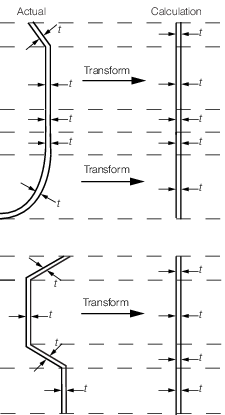
Figure 6.2.1 Effective shear area
2.5 Torsional strength
2.5.1 Torsional
stresses are typically small for monohulls of ordinary form of Rule
length, L
R, less than 75 m and can generally
be ignored.
2.5.2 The calculation
of torsional stresses and/or deflections may be required when considering
craft with large deck openings, unusual form or proportions. Calculations
may in general be required to be carried out using a direct calculation
procedure. Such calculations are to be submitted in accordance with Pt 6, Ch 6, 1.5 Direct calculation procedure.
2.6 Superstructures global strength
2.6.1 Where the side walls of superstructures are aligned with the side shell and
these side walls are fully plated with scantlings as for side shell, the effect of the
superstructure in global strength can be estimated from paragraphs Pt 6, Ch 6, 2.6 Superstructures global strength 2.6.2 to Pt 6, Ch 6, 2.6 Superstructures global strength 2.6.6. In case there are openings in the side walls that would
affect the connection of the superstructure deck with the hull, or when the side walls
are not in-line with the side shell, the effectiveness of the superstructure in global
strength is to be determined by direct calculation.
2.6.2 The effectiveness of the superstructure in absorbing hull girder bending
loads is to be established where the first tier of the superstructure extends within
0,4L amidships and where:
where
 1
1
|
= |
length of first tier, in metres |
|
b
1
|
= |
breadth of first tier, in metres |
|
h
1
|
= |
'tween deck height of first tier, in metres |
2.6.3 For superstructures with one or two tiers extending outboard to the craft's
side shell, the effectiveness in absorbing hull girder bending loads in the uppermost
effective tier may be assessed by the following factor:
where
|
f(λ, N=1) |
= |
1 |
|
f(λ, N=2) |
= |
0,90λ3 – 2,17λ2 + 1,73λ + 0,50 |
and
|
N
|
= |
1 if  2 < 0,7
 1
1
|
|
|
= |
2 if  2 ≥ 0,7
 1
1
|
|
λ |
= |
 or 1, whichever is less or 1, whichever is less |
|
ε |
= |
 or 5, whichever is less or 5, whichever is less |
|
γ |
= |
 or 25, whichever is less or 25, whichever is less |
 w
w
|
= |
 1 for N = 1
 |
|
|
= |
 for N = 2 for N = 2 |
|
L
R
|
= |
as defined in Pt 6, Ch 6, 1.2 Symbols and definitions 1.2.1, in metres |
 1, b
1, h
1
1, b
1, h
1
|
= |
as defined in Pt 6, Ch 6, 2.5 Torsional strength 2.5.1, in metres |
 2
2
|
= |
length of second tier, in metres. |
2.6.4 The hull girder compressive bending stress σL, in the uppermost
effective tier at side may be derived according to the following formula:
2.6.5 The compressive stress, σL, in the uppermost effective tier at
side is to be checked against buckling in accordance with Pt 6, Ch 7, 4 Buckling control.
2.6.6 The uppermost effective tier may need to fulfil the requirements for
strength deck when the following applies:
where
|
ηs
|
= |
as defined in Pt 6, Ch 6, 2.6 Superstructures global strength 2.6.3
|
|
Z
0
|
= |
section modulus of hull only at hull upper deck, in m3
|
 100
100
|
= |
moment of inertia of hull and effective tiers, assuming tiers to be
100 per cent effective, in m4
|
|
h
|
= |
height from hull upper deck to uppermost effective tier, in
metres. |
2.6.7 The deformation of large openings in side walls of superstructures is to be
investigated. They should not exceed the deformation limit of the closing appliances.
|